Table of Contents
Advertisement
harman/kardon
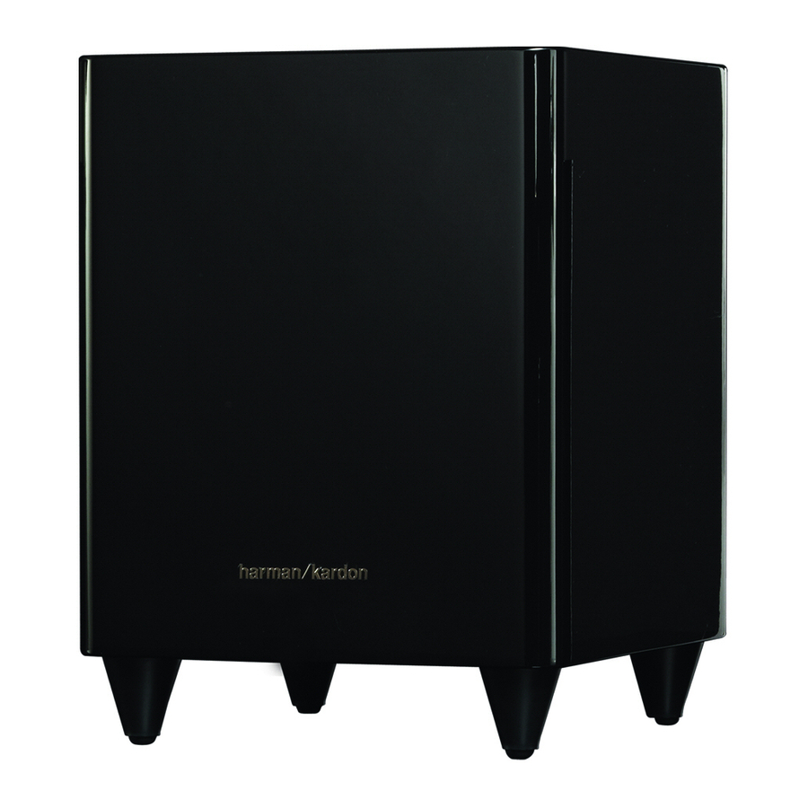
HKTS 200/230 SUB
HKTS 210/230 SUB
Active subwoofers.
Part of systems HKTS 20, HKTS 30 and HKTS 60 and
more.
Also sold separately.
Released EU2011
CONTENTS
2
3
4
5
6
7
Harman Consumer Group, Inc.
8500 Balboa Boulevard
Northridge, California 91329
Service Manual
Rev 2, 04/2011
8
9
10
11
13-18
Advertisement
Table of Contents

Summarization of Contents
HKTS200SUB Rear-Panel Connections
Subwoofer Level Control
Adjusts the subwoofer's volume; turn clockwise to increase, counterclockwise to decrease.
Bass Boost Switch
Enhances low-frequency performance when ON, normal performance when OFF.
Phase Switch
Determines if subwoofer action is in phase with satellite speakers for optimal bass.
Power On Mode Switch
Controls automatic power-on/standby based on audio signal or trigger.
External Trigger Input
Connects to a trigger output (3-30V) to automatically turn the subwoofer on/off.
Line-Level LFE In Connector
Bypasses internal crossover for dedicated subwoofer outputs.
Line-Level L/R In Connectors
Used when receiver lacks dedicated low-pass filtered subwoofer output.
Power Switch
Turns the subwoofer on or puts it into standby mode.
Power Cord
Connect to an active, unswitched electrical outlet for proper operation.
HKTS 210SUB Rear-Panel Connections
Phase Switch
Ensures subwoofer piston action is in phase with satellite speakers for optimal bass.
Bass Boost Switch
Enhances low-frequency performance when ON, normal when OFF.
Power On Mode Switch
Controls auto turn-on/standby based on audio signal or trigger.
Subwoofer Level Control
Adjusts the subwoofer's volume; clockwise for increase, counterclockwise for decrease.
Input Mode Switch
Selects between 'Normal' (L/R) or 'LFE' input signals for the subwoofer.
External Trigger Input
Connects to a trigger output (3-30V) to automatically turn the subwoofer on/off.
Line-Level LFE In Connector
Bypasses internal crossover for dedicated low-pass filtered subwoofer outputs.
Line-Level L/R In Connectors
Passes through internal low-pass crossover; use if no dedicated receiver output.
Power Switch
Turns the subwoofer on or puts it into standby mode.
Power Cord
Connect to an active, unswitched electrical outlet for proper operation.
Color-Coding System
System for easy home theater speaker setup using CEA color coding.
Operation and Adjustments
Turning the Subwoofer On and Off
Instructions for powering the subwoofer using the Power Switch and Power On Mode Switch.
Subwoofer Adjustments: Volume
Using the Subwoofer Level Control to set the desired volume.
Subwoofer Adjustments: Phase
Setting the Phase Switch for optimal bass response and impact.
Subwoofer Adjustments: Bass Boost
Using the Bass Boost Switch to enhance low-frequency performance.
Troubleshooting HKTS System
No Sound from Speakers
Troubleshooting steps for no sound from any or specific speakers.
No Sound from One Speaker
Specific checks for no sound from one speaker.
No Sound from Center Speaker
Specific checks for no sound from the center channel speaker.
Technical Specifications
HKTS 60BQ/230 System Specifications
Frequency response details for the HKTS 60BQ/230 system.
SAT-TS60 Satellite Specifications
Power, impedance, sensitivity, and dimensions for SAT-TS60 satellites.
CEN-TS60 Satellite Specifications
Power, impedance, sensitivity, and dimensions for CEN-TS60 satellites.
HKTS 210SUB Subwoofer Specifications
Power requirements, amplifier power, woofer, and dimensions for HKTS 210SUB.
HKTS 200SUB Exploded View and Parts
HKTS 200SUB Exploded View Diagram
Visual representation of the HKTS 200SUB subwoofer components and their assembly.
HKTS 210SUB Exploded View and Parts
HKTS 210SUB Exploded View Diagram
Visual representation of the HKTS 210SUB subwoofer components and their assembly.
Semiconductor Component Information
MOSFET Component Datasheet
Technical specifications for the FTP14N50C/FTA14N50C MOSFET.
MOSFET Electrical and Thermal Ratings
Details on maximum ratings and thermal resistance for the specified MOSFETs.
HKTS 210SUB Schematic Diagrams
Power Supply Schematics
Schematic diagrams for the power supply sections of the HKTS 210SUB.
Control and Input Schematics
Schematic diagrams for the control and input sections of the HKTS 210SUB.


Need help?
Do you have a question about the HKTS 210/230 SUB and is the answer not in the manual?
Questions and answers