Advertisement
Table of Contents
O
PERATOR'S
IMPORTANT: READ SAFETY RULES AND INSTRUCTIONS CAREFULLY
Warning:
This unit is equipped with an internal combustion engine and should not be used on or near any unimproved forest-
covered, brush-covered or grass-covered land unless the engine's exhaust system is equipped with a spark arrester meeting
applicable local or state laws (if any). If a spark arrester is used, it should be maintained in effective working order by the operator.
In the State of California the above is required by law (Section 4442 of the California Public Resources Code). Other states may have
similar laws. Federal laws apply on federal lands. A spark arrester for the muffler is available through your nearest engine authorized
service dealer or contact the service department, P.O. Box 368022 Cleveland, Ohio 44136-9722.
MTD PRODUCTS INC. P.O. BOX 368022 CLEVELAND, OHIO 44136-9722
PRINTED IN U.S.A.
M
ANUAL
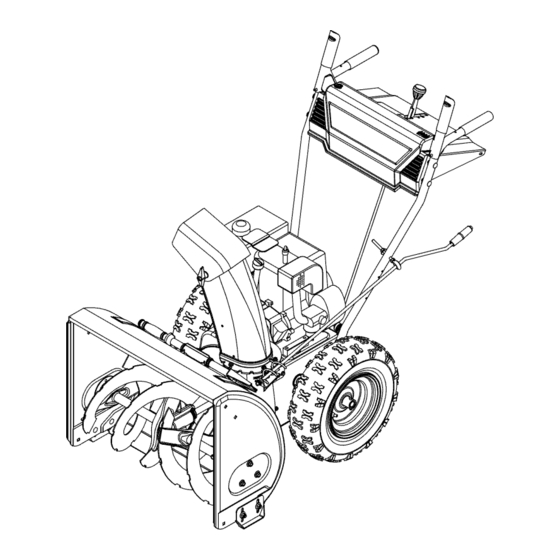
SNOW THROWER
MODELS
E600E, E610E
E640F, E660G
FORM NO
. 770-10002E.fm
(5/2001)
Advertisement
Table of Contents

Related Manuals for MTD E640F


Summarization of Contents
SECTION 1: IMPORTANT SAFE OPERATION PRACTICES
Training and Safety Rules
Read and follow all instructions. Be familiar with controls and never allow children to operate.
Preparation for Operation
Inspect the area, wear safety glasses, use adequate winter garments, and avoid loose clothing.
Operation Safety Guidelines
Exercise caution, keep bystanders away, and avoid slippery surfaces or falling.
Maintenance and Storage
Maintenance Procedures
Check bolts, screws, safety devices, and adjust controls. Maintain or replace safety labels.
Storage Guidelines
Clean machine, lubricate parts, and store in a well-ventilated area away from ignition sources.
Contents Of Hardware Pack
Hardware Identification for Assembly
Lay out hardware for identification. Part numbers are shown in parentheses for assembly steps.
SECTION 2: ASSEMBLING YOUR SNOW THROWER
Unpacking and Loose Parts
Remove staples, lay carton flat, remove packing material, and check for loose parts before discarding.
Attaching the Handles and Panel
Secure handles to the snow thrower and attach the handle panel using provided hardware.
Attaching Control Cables and Chute Assembly
Connect control cables and attach the chute assembly using flange keepers and hex bolts.
Attaching Chute Directional Control
Install the chute directional control, ensuring proper engagement with the chute assembly.
Attaching the Shift Rod
Connect the shift rod to the shift arm assembly and shift lever, ensuring correct alignment.
Lamp Wiring
Route the lamp wire and connect it to the alternator lead wire under the fuel tank.
SECTION 3: KNOW YOUR SNOW THROWER
Operating Controls Overview
Familiarize yourself with all controls: Shift Lever, Auger Control, Traction Control, Chute Controls.
Starting and Fuel Systems
Understand ignition key operation, choke control, and fuel shut-off valve (if equipped).
SECTION 4: OPERATING YOUR SNOW THROWER
Before Starting Checks
Read warnings, connect spark plug wire, and ensure proper fuel and oil levels.
Starting the Engine
Use recoil or electric starter. Follow choke and primer instructions for cold or warm engines.
Stopping the Engine and Drive Engagement
Remove ignition key to stop. Engage drive by selecting speed and squeezing traction control.
Engaging Augers and Operating Tips
Squeeze auger control to engage. Discharge snow downwind and adjust skid shoes as needed.
SECTION 5: MAKING ADJUSTMENTS
Traction Control and Shift Rod Adjustment
Adjust traction control and shift rod for proper engagement and smooth operation.
Drive Wheels Configuration
Configure drive wheels for one-wheel or both-wheel drive by inserting click pins.
SECTION 6: MAINTAINING YOUR SNOW THROWER
Lubrication Guide
Lubricate chute directional control, wheels, gear shaft, and drive/shifting mechanism.
Gear Case, Engine, and Auger Shaft Maintenance
Check gear case grease, refer to engine manual, and lubricate auger shaft bearings.
SECTION 7: SERVICE
Auger Shear Bolt and Shave Plate Service
Check auger shear bolts if augers won't turn. Service shave plate and skid shoes for wear.
Belt Replacement
Disconnect spark plug wire. Remove belt cover, unhook spring, and remove belts from pulleys.
Drive Belt and Friction Wheel Service
Replace drive belts and friction wheel rubber as needed, following reverse order of disassembly.
SECTION 8: OFF-SEASON STORAGE
Storage Precautions
Never store with fuel indoors. Clean and lubricate machine before storing.
SECTION 9: TROUBLE SHOOTING GUIDE
Engine Start and Running Issues
Troubleshoot engine failure to start or erratic running by checking fuel, choke, plug, and carburetor.
Power, Discharge, and Vibration Issues
Address loss of power, overheats, unit not propelling, or discharge chute issues.
MANUFACTURER'S LIMITED WARRANTY
Warranty Coverage and Exclusions
Covers defects for 2 years; wear parts for 90 days. Excludes misuse, accidents, and unauthorized parts.
Obtaining Warranty Service
Contact authorized dealer with proof of purchase or call MTD Customer Service.
Need help?
Do you have a question about the E640F and is the answer not in the manual?
Questions and answers