Table of Contents
Advertisement
OPERATOR'S MANUAL
SNOW THROWER
Models 615, E6AE5,
E645E, & E665F
IMPORTANT: READ SAFETY RULES AND INSTRUCTIONS CAREFULLY
Warning:
This unit is equipped with an internal combustion engine and should not be used on or near any unimproved forest-
covered, brush-covered or grass-covered land unless the engine's exhaust system is equipped with a spark arrester meeting
applicable local or state laws (if any). If a spark arrester is used, it should be maintained in effective working order by the operator.
In the State of California the above is required by law (Section 4442 of the California Public Resources Code). Other states may have
similar laws. Federal laws apply on federal lands. A spark arrester for the muffler is available through your nearest engine authorized
service dealer or contact the service department, P.O. Box 361131 Cleveland, Ohio 44136-0019.
MTD LLC, P.O. BOX 361131 CLEVELAND, OHIO 44136-0019
PRINTED IN U.S.A.
770-10025F.fm
FORM NO.
(6/2003)
Advertisement
Table of Contents

Related Manuals for MTD 615


Summary of Contents for MTD 615
-
Page 1: Snow Thrower
Federal laws apply on federal lands. A spark arrester for the muffler is available through your nearest engine authorized service dealer or contact the service department, P.O. Box 361131 Cleveland, Ohio 44136-0019. MTD LLC, P.O. BOX 361131 CLEVELAND, OHIO 44136-0019 PRINTED IN U.S.A. -
Page 2: Table Of Contents
A sample model plate is explained below. For future reference, please copy the model number and the serial number of the equipment in the space below. Copy the model number here: Copy the serial number here: MTD LLC P. O. BOX 361131 CLEVELAND,OH 44136 330-220-4683 www.mtdproducts.com... -
Page 3: Important Safe Operation Practices
SECTION 1: IMPORTANT SAFE OPERATION PRACTICES This symbol points out important safety instructions, which if not followed, could endanger the personal safety and/or property of yourself and others. Read and follow all instructions in this manual before attempting to operate this machine. Failure to comply with these instructions may result in personal injury. -
Page 4: Maintenance And Storage
Never operate with a missing or damaged discharge Contact your dealer or telephone 1-800-800-7310 for chute. Keep all safety devices in place and working. assistance and the name of your nearest servicing Never run an engine indoors or in a poorly ventilated dealer. -
Page 5: Hardware Pack
Contents Of Hardware Pack Lay out the hardware according to the illustration below for identification purposes. Part numbers are shown in parentheses. (Hardware pack may contain extra items which are not used on your unit.) ATTACHING THE HANDLES ATTACHING HANDLE PANEL Carriage Bolts 5/16-18 x 1-1/2”... -
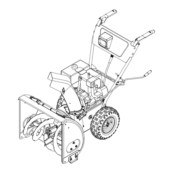
Page 6: Assembling Your Snow Thrower
SECTION 2: ASSEMBLING YOUR SNOW THROWER Loose Parts Attaching Handles Figure 1 shows parts of the snow thrower packed loose (Hardware Groups A) in the carton. You will need these parts along with • Insert each hex bolt and lock washer through the hardware from the hardware pack, illustrated on the bottom hole in the handle and bottom hole in snow next page, to assembly the equipment. - Page 7 • Insert the shift lever assembly through slot in the • Insert curved end of the Z fitting into the top hole in speed selector plate leaving the hex bolts on the the triangular metal tab on the auger control grip. shift lever assembly loose, but not removed.
- Page 8 If the right hand lock-out cable is not • Thread one hex nut onto the eyebolt on the chute IMPORTANT: adjusted correctly, the wheels will tend to turn. If the left directional control assembly until there is at least hand lock-out cable is not adjusted correctly, the two inches of threads showing between the nut and augers will keep on rotating.
-
Page 9: Know Your Snow Thrower
Attaching Lamp Wire • Adjust the chute directional control bracket so that (If equipped) the spiral on the chute directional control fully If for shipping purposes, the headlight wire was left engages the teeth on the chute assembly. Tighten unattached to the alternator lead, follow the steps all hardware. -
Page 10: Operating Your Snow Thrower
Throttle Control Safety Ignition Key The throttle control is located on the engine. It regulates The safety ignition key must be fully inserted in the the speed of the engine and will shut off the engine switch before the unit will start. Remove the ignition key when pushed down completely. - Page 11 To prevent starter freeze-up: WARNING: The electric starter must be used with a properly grounded three-prong • Run engine for a few minutes before stopping to receptacle at all times to avoid possibility of help dry off any moisture on the engine. electric shock.
- Page 12 Chute Clean-out Tool Check the adjustment of the auger control as follows: • When the auger control is released and in the The chute clean-out tool is conveniently fastened to the disengaged “up” position, the cable should have rear of the auger housing with a mounting clip (Refer to very little slack, but should NOT be tight.
-
Page 13: Making Adjustments
Operating Tips • Discharge snow downwind whenever possible. Slightly overlap each previous path. • Set the skid shoes 1/4” below the scraper bar for NOTE: Allow the engine to warm up for a few minutes normal usage. The skid shoes may be adjusted as the engine will not develop full power until it reaches upward for hard-packed snow. -
Page 14: Maintaining Your Snow Thrower
Chute Assembly Carburetor The distance snow is thrown can be adjusted by WARNING: If any adjustments need to be changing the angle of the chute assembly. To do so, made to the engine while the engine is running stop the engine by removing the ignition key and loosen (e.g. -
Page 15: Service
Chute Directional Control WARNING: When following instructions in separate engine manual for draining oil, be • The worm gear on the chute directional control sure to protect frame to avoid oil dripping onto should be greased with multipurpose automotive transmission parts. grease. -
Page 16: Belt Removal And Replacement
NEVER replace the auger shear bolts with IMPORTANT: Drive Belt standard hex bolts. Any damage to the auger gearbox Auger or other components as a result of doing so will NOT be Belt Drive covered by your snow thrower’s warranty. Pulley Shave Plate and Skid Shoes The shave plate and skid shoes on the bottom of the... - Page 17 Drive Belt • Remove six self-tapping screws from the frame cover underneath the snow thrower. • Follow steps 1 through 4 of steps previous • Remove the klick pins which secure the wheels, instructions. and remove the wheels from the axle. •...
-
Page 18: Troubleshooting
SECTION 8: OFF-SEASON STORAGE WARNING: • Remove all dirt from exterior of engine and Never store the machine or equipment. fuel container indoors where there is an open • Follow instructions recommendations on page 15. flame, spark or pilot light such as on a water heater, furnace, clothes dryer or other gas NOTE: When storing any type of power equipment in appliances. -
Page 19: Parts List
SECTION 10: PARTS LIST FOR MODEL SERIES 615, E6A5, E645 & E665 Ref. Part Description 618-0123 Housing—R.H. 618-0124 Housing—L.H. 710-0642 Hex Screw 1/4-20 x .75 711-1020A Spiral Axle 22” 711-0908A Spiral Axle 24” 711-0909A Spiral Axle 26” 714-0161 715-0143 Pin-Spiral... - Page 20 Model Series 615, E6A5, E645 & E665 9 18 19...
- Page 21 Model Series 615, E6A5, E645 & E665 Ref. Part Description Ref. Part Description 712-0798 Hex Nut 3/8-16 712-0116 Lock Jam Nut 3/8-24 710-0451 Carriage Bolt 5/16-18 x .75 756-0178 Flat Idler 784-5580 Snow Shoe 784-5632B Auger Idler Arm 736-0242 Bell Washer 710-0459A Hex Cap Screw 3/8-24 x 1.50...
- Page 22 Model Series E6A5E, E645E & E665E IMPORTANT: proper working machine, use Factory Approved Parts. V-BELTS are specially designed to engage and disengage safely. A substitute (non OEM) V-Belt can be dangerous by not disengaging completely. Ref. Part Ref. Part Description Description 710-1652 Hex Washer Screw 1/4-20 x .50...
- Page 23 Model Series 615 IMPORTANT: proper working machine, use Factory Approved Parts. V-BELTS are specially designed to engage and disengage safely. A substitute (non OEM) V-Belt can be dangerous by not disengaging completely. Ref. Part Description Ref. Part Description 710-1652 Hex Washer Screw 1/4-20 x.5...
- Page 24 Models Series 615, E6A5E, E645E & E665E...
- Page 25 Models Series 615, E6A5E, E645E & E665E Ref. Part Ref. Part Description Description 705-5234A Clutch Lever Assembly - RH 29. 710-1652 Hex Washer Screw 1/4-20 x .625 † 705-5233A Clutch Lever Assembly - LH 30. 710-1003 Hex Washer Screw #10 16 x .625 †...
- Page 26 Models Series 615, E6A5E, E645E & E665E Drive Clutch Cable Auger Clutch Cable 16” Wheels 13” or 15” Wheels 9 10 Blower Housing...
- Page 27 Models Series 615, E6A5E, E645E & E665E Ref. Part No. Description Ref. Part No. Description 710-1652 Hex Screw 715-0249 Roll Pin 784-5688 Drive Cable Guide Bracket 714-0143 Klik Pin 784-5687A Auger Clutch Cable Bracket 684-0042C Friction Wheel Assembly 756-0625 Roller Cable...
- Page 28 MANUFACTURER’S LIMITED WARRANTY FOR: The limited warranty set forth below is given by MTD LLC with MTD does not extend any warranty for products sold or respect to new merchandise purchased and used in the exported outside of the United States, its possessions United States, its possessions and territories.
Need help?
Do you have a question about the 615 and is the answer not in the manual?
Questions and answers