Honeywell HW5500 - 5500 Portable Generator Service Manual
Service manual
Hide thumbs
Also See for HW5500 - 5500 Portable Generator:
- Owner's manual (47 pages) ,
- Parts manual (7 pages) ,
- Specification sheet (1 page)
Table of Contents
Advertisement
Advertisement
Table of Contents

Related Manuals for Honeywell HW5500 - 5500 Portable Generator


Summary of Contents for Honeywell HW5500 - 5500 Portable Generator
- Page 1 Portable Electrical Generator Service Manual HW3000/L HW4000/L HW5500/L HW5500E/L HW6200/L HW7000E/L HW7500E/L Read and Save These Instructions For technical support and parts, contact your Regional Master Parts Distributor toll-free at 1-877-HWTECHS (498-3247) or visit www.honeywellgenerators.com.
-
Page 3: Table Of Contents
MUFFLER ..............................9-6 CARBURETOR ............................9-7 STARTING SYSTEM ..........................9-8 RECOIL STARTER ..........................9-9 FAN COVER ............................9-10 WHEEL, LEG, & HANDLE ASSEMBLY (HW3000/L MODELS) .............9-11 WHEEL, LEG, & HANDLE ASSEMBLY (ALL MODELS EXCEPT HW3000/L) ........9-12 INDEX .......................... 10-1 Honeywell Portable Electrical Generator Service Manual www.honeywellgenerators.com... - Page 4 THIS PAGE INTENTIONALLY LEFT BLANK www.honeywellgenerators.com Honeywell Portable Electrical Generator Service Manual...
-
Page 5: Important Safety Instructions
• Use the correct tool for the job and check its condition before starting. • Keep fire extinguishers and safety equipment nearby. Honeywell Portable Electrical Generator Service Manual www.honeywellgenerators.com... -
Page 6: Safety Messages
• Be careful not to spill fuel when refueling. Spilled fuel or fuel vapor may ignite. If any fuel is spilled, the area must be dry before starting the engine. • Avoid repeated or prolonged contact with skin or breathing of vapor. www.honeywellgenerators.com Honeywell Portable Electrical Generator Service Manual... -
Page 7: Warranties
Warranty is also available by keeping and showing your origi- excludes any use of this product intended to power life sup- nal receipt from date of purchase to an authorized Honeywell port devices, life support appliances, medical devices, or Generator Dealer. -
Page 8: Northshore Power Systems Emissions Control Warranty
Honeywell generator parts in performance and durability. 1-877-HWTECHS (498-3247). Length of Coverage. Northshore Power Systems war- rants to the original retail purchaser and each subse- 2.1 WARRANTIES... - Page 9 Honeywell Generator Owner's Manual. Any replacement part that is equivalent in per- formance and durability may be used for maintenance or repairs.
-
Page 10: Northshore Power Systems Replacement Parts Limited Warranty
OF INCOME, LOSS OF TIME, LOSS OF SALES, INJURY TO PERSONAL PROPERTY, OR LIABILITY CUSTOMER INCURS WITH RESPECT TO ANY OTHER PERSON, OR ANY OTHER TYPE OR FORM OF CONSEQUENTIAL DAM- AGE OR ECONOMIC LOSS. www.honeywellgenerators.com Honeywell Portable Electrical Generator Service Manual... -
Page 11: Specifications And Wiring Diagrams
101536A 101536A (Electric Start Models Only) TABLE 3-1: Honeywell Portable Generator Specifications See ENGINE OIL RECOMMENDATIONS, page 7-3 for other engine oil types outside general temperature use. † See SPARK PLUG SERVICE, page 7-5 for other recommended spark plug replacements. -
Page 12: Bolt And Fastener Torque Information
Support Leg to Frame Bolts M8 x 1.0 x 16 Support Leg to Rubber Stopper Bolts M8 x 1.0 x 25 Wheel Handle Pivot Bracket Bolts M6 x 1.0 x 40 TABLE 3-3: Torque Values www.honeywellgenerators.com Honeywell Portable Electrical Generator Service Manual... -
Page 13: Wiring Diagrams
WIRING DIAGRAMS 3.3 WIRING DIAGRAMS HW3000 & HW3000L FIGURE 3-1: HW3000 & HW3000L Wiring Diagram Honeywell Portable Electrical Generator Service Manual www.honeywellgenerators.com... - Page 14 WIRING DIAGRAMS HW4000 & HW4000L FIGURE 3-2: HW4000 & HW4000L Wiring Diagram www.honeywellgenerators.com Honeywell Portable Electrical Generator Service Manual...
- Page 15 WIRING DIAGRAMS HW5500 & HW5500L FIGURE 3-3: HW5500 & HW5500L Wiring Diagram Honeywell Portable Electrical Generator Service Manual www.honeywellgenerators.com...
- Page 16 WIRING DIAGRAMS HW5500E & HW5500EL FIGURE 3-4: HW5500E & HW5500EL Wiring Diagram www.honeywellgenerators.com Honeywell Portable Electrical Generator Service Manual...
- Page 17 WIRING DIAGRAMS HW6200 & HW6200L FIGURE 3-5: HW6200 & HW6200L Wiring Diagram Honeywell Portable Electrical Generator Service Manual www.honeywellgenerators.com...
- Page 18 WIRING DIAGRAMS HW7000E, HW7000EL, HW7500E, & HW7500EL FIGURE 3-6: HW7000E, HW7000EL, HW7500E & HW7500EL Wiring Diagram www.honeywellgenerators.com Honeywell Portable Electrical Generator Service Manual...
-
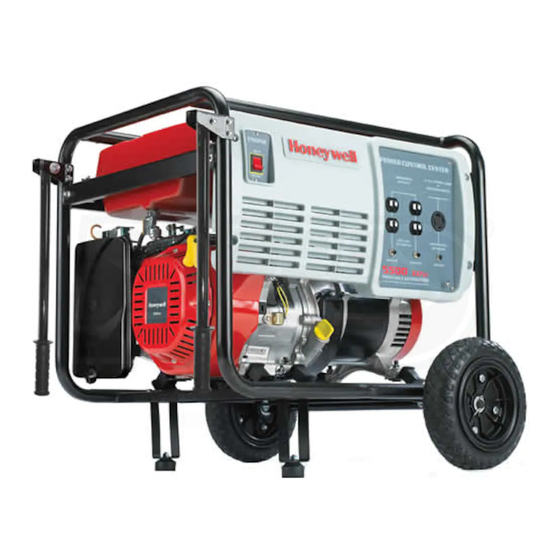
Page 19: Components
4: COMPONENTS FIGURE 4-1: Honeywell Portable Electrical Generator Controls and Components (HW5500EL Model Illustrated) A—Power Control Center E—Engine Control Switch Control used to start and stop the engine ignition system. Electrical Outlets • • START—Starts generator engine (electric start models) 125VAC 20 Amp Duplex (NEMA 5-20R) outlets to connect •... - Page 20 THIS PAGE INTENTIONALLY LEFT BLANK www.honeywellgenerators.com Honeywell Portable Electrical Generator Service Manual...
-
Page 21: Preparing For Service
Keep the generator level to prevent fuel spillage. • Place pins in the handle and handle bracket before moving the generator. NOTICE NEVER drop, strike, or place heavy objects on generator when transporting. Honeywell Portable Electrical Generator Service Manual www.honeywellgenerators.com... - Page 22 THIS PAGE INTENTIONALLY LEFT BLANK www.honeywellgenerators.com Honeywell Portable Electrical Generator Service Manual...
-
Page 23: Service Repair Time Analysis & Flat Rate Schedule
Governor Assembly Head Cover Gasket FUEL & EXHAUST Carbon Canister (with bracket) (Model Numbers Ending in “L”) Carbon Canister Tube (Model Numbers Ending in “L”) Exhaust Pipe (Model Numbers Ending in “L”) Fuel Gage Honeywell Portable Electrical Generator Service Manual www.honeywellgenerators.com... - Page 24 Repair times represent generally accepted intervals for conducting a repair. Service centers are always advised to provide feedback during the warranty claim process if additional time may be needed due to unforeseen circumstances. 6.1 SERVICE REPAIR TIME ANALYSIS www.honeywellgenerators.com Honeywell Portable Electrical Generator Service Manual...
-
Page 25: Maintenance
If the generator is stored for more than a year without running, a battery charger may required to recharge the generator battery. ** It is recommended that this maintenance task be performed by a service dealer. Honeywell Portable Electrical Generator Service Manual www.honeywellgenerators.com... -
Page 26: Consumer Maintenance Schedule
87 or higher. Some states (and provinces in Canada) require this infor- mation to be posted on the fuel pump. If you notice unde- sirable operating symptoms, switch to a conventional unleaded gasoline. www.honeywellgenerators.com Honeywell Portable Electrical Generator Service Manual... -
Page 27: Air Filter Maintenance
ALWAYS stop engine before removing oil fill dip- stick. Crankcase pressure can cause hot engine oil to spray out of engine fill hole. Hot engine oil can cause severe burns. FIGURE 7-3: Air Cleaner Cover—Non-L Models Honeywell Portable Electrical Generator Service Manual www.honeywellgenerators.com... - Page 28 FIGURE 7-8: Excess Oil Removal CAUTION Frequent or prolonged contact with engine oil may cause skin cancer. • Thoroughly wash hands and any areas of skin exposed to used oil with soap and water. www.honeywellgenerators.com Honeywell Portable Electrical Generator Service Manual...
-
Page 29: Cleaning Fuel Sediment Cup
Reinstall the sediment cup, o-ring, and fuel screen. Champion RN9YC Turn the fuel shut-off valve to the ON position. Denso W20EPR Start generator and check for leaks. BPR6ES TABLE 7-4. Spark Plug Equivalents to 100842A Honeywell Portable Electrical Generator Service Manual www.honeywellgenerators.com... -
Page 30: Cleaning Spark Arrestor Screen
HW3000 or HW3000L models). Remove muffler cover. FIGURE 7-16: Clean Screen Reinstall remaining spark arrestor components. Spark arrestor screen cap and screw „ Clamp and screw „ „ Muffler cover FIGURE 7-14: Remove Muffler Cover www.honeywellgenerators.com Honeywell Portable Electrical Generator Service Manual... -
Page 31: Valve Lash
12 N•m (9 lb. ft.). Check valve lash again after tightening lock nut. Repeat steps 4 through 7, as needed, until valve lash is within specifications. Reassemble the spark plug, cylinder head cover, and gasket. Honeywell Portable Electrical Generator Service Manual www.honeywellgenerators.com... -
Page 32: Battery Service
Tip battery slightly forward. Disconnect the black negative (-) battery lead remov- ing the bolt and nut. FIGURE 7-21: Electric Start Battery—Lead Connection Disconnect the red positive (+) battery lead removing the bolt and nut. www.honeywellgenerators.com Honeywell Portable Electrical Generator Service Manual... -
Page 33: Troubleshooting
NEVER use inside a home far away from windows, or garage, EVEN IF doors doors, and vents. and windows are open. NOTE: For all dealer service inquiries, call 1-877-HWTECHS (498-3247) or visit www.honeywellgenerators.com. Honeywell Portable Electrical Generator Service Manual www.honeywellgenerators.com... -
Page 34: Electrical Diagnostics (Hw3000/L Models)
Check Output Voltage (X to W) of Duplex Outlet #1= 123-126V Adjust Voltage Regulator, if Necessary by Turning the Potentiometer on the Rear of the Voltage Regulator If Voltage Still Out of Range Replace Voltage Regulator www.honeywellgenerators.com Honeywell Portable Electrical Generator Service Manual... - Page 35 ELECTRICAL DIAGNOSTICS (HW3000/L MODELS) See “Specifications” Page For Rated Power, Voltage, & Frequency Specs Under Load and No Load Conditions Honeywell Portable Electrical Generator Service Manual www.honeywellgenerators.com...
- Page 36 AVR Tap Stator-X Resistance Exciter Yellow Yellow Slip Rings Rotor 45 - 65 Slip Ring Terminals* If a Winding Resistance is Out of Spec, Replace Alternator Specification AVR Tap Either Exciter Yellow Replace Alternator www.honeywellgenerators.com Honeywell Portable Electrical Generator Service Manual...
- Page 37 ELECTRICAL DIAGNOSTICS (HW3000/L MODELS) Blue Wire Yellow Wire 5-9 mm Honeywell Portable Electrical Generator Service Manual www.honeywellgenerators.com...
-
Page 38: Electrical Diagnostics (All Models Except Hw3000/L)
Check Output Voltage (X to Y) of the 240V Receptacle = 246-252V Adjust Voltage Regulator, if Necessary by Turning the Potentiometer on the Rear of the Voltage Regulator If Voltage Still Out of Range Replace Voltage Regulator www.honeywellgenerators.com Honeywell Portable Electrical Generator Service Manual... - Page 39 ELECTRICAL DIAGNOSTICS (ALL MODELS EXCEPT HW3000/L) See “Specifications” Page For Rated Power, Voltage, & Frequency Specs Under Load and No Load Conditions Honeywell Portable Electrical Generator Service Manual www.honeywellgenerators.com...
- Page 40 If a Winding Resistance is Out of Spec, Replace Alternator Specification Stator-X Red Stator-Y White Stator-X Red AVR Tap Green Stator-Y White AVR Tap Green Stator-X Red Stator-Y White Stator-X Red Stator-Y White Replace Alternator www.honeywellgenerators.com Honeywell Portable Electrical Generator Service Manual...
- Page 41 ELECTRICAL DIAGNOSTICS (ALL MODELS EXCEPT HW3000/L) Red Wire White Wire 5-9 mm Honeywell Portable Electrical Generator Service Manual www.honeywellgenerators.com...
-
Page 42: Engine Diagnostics (All Models)
Check Oil Overfilled Frequency = 60 Hz + 3 Disassemble and Repair Check Worn Piston Rings Broken Ratchets or Springs (see Manual Section “Recoil Starter”) Check Governor Assembly Perform Engine Compression Test Adjustment 8-10 www.honeywellgenerators.com Honeywell Portable Electrical Generator Service Manual... -
Page 43: Service And Disassembly
E—SWITCH PLATE (FRONT) • E1 - Electric Start Models (HW5500E, HW5500EL, HW7000E, HW7000EL, HW7500E, HW7500EL) • E2 - Manual Start Models (HW3000, HW3000L, HW4000, HW4000L, HW5500, HW5500L, HW6200, HW6200L) F—ENGINE CONTROL SWITCH G—SWITCH PLATE (BACK) Honeywell Portable Electrical Generator Service Manual www.honeywellgenerators.com... -
Page 44: Engine And Alternator
Refer to illustration for proper positioning. NOTE: On some models there are only 4 vibration isolators instead of 6. H—FRAME See WHEEL, LEG, & HANDLE ASSEMBLY, page 9-11. I— CRANKCASE COVER 28 N•m (21 lb. ft.) www.honeywellgenerators.com Honeywell Portable Electrical Generator Service Manual... -
Page 45: Alternator
H—GROUND CABLE I— EXCITER WINDING CONNECTOR J—BRUSH ASSEMBLY K—TERMINAL BLOCK L—SLIP RINGS M—FUEL CUTOUT CONNECTOR N—VOLTAGE REGULATOR Also known as Automatic Voltage Regulator or AVR. Alternator Illustrated Matches All Models Except HW3000 & HW3000L Honeywell Portable Electrical Generator Service Manual www.honeywellgenerators.com... -
Page 46: Fuel Tank System
After reinstalling, check for fuel leakage. Hex fitting - 24 N•m (17 lb. ft.) G—FUEL SEDIMENT CUP See CLEANING FUEL SEDIMENT HW7500E Model Illustrated CUP, page 7-5. H—FUEL LINE Check for cracks or damage. Secure with hose clamps. www.honeywellgenerators.com Honeywell Portable Electrical Generator Service Manual... -
Page 47: Evaporative Emissions Control System
C—VAPOR LINE Secure with hose clamps. D—CARBON CANISTER TUBE Secure with hose clamps. E—CARBON CANISTER BRACKET 2 N•m (1.5 lb. ft.) • E1 - HW3000L Model Only • E2 - All Other Models Honeywell Portable Electrical Generator Service Manual www.honeywellgenerators.com... -
Page 48: Muffler
(HW3000L, HW4000L, HW5500L, HW5500EL, HW6200L, HW7000EL, HW7500EL) F—SECONDARY AIR INTAKE VALVE For model numbers ending in “L” only (HW3000L, HW4000L, HW5500L, HW5500EL, HW6200L, HW7000EL, HW7500EL) G—MUFFLER SIDE GUARD 4 N•m (3 lb. ft.) www.honeywellgenerators.com Honeywell Portable Electrical Generator Service Manual... -
Page 49: Carburetor
Clean with compressed air before installation. G—MAIN NOZZLE Clean with compressed air before installation. H—O-RING Check for correct installation. I— CARBURETOR BODY Clean internal passages and orifices with compressed air before installa- tion. Honeywell Portable Electrical Generator Service Manual www.honeywellgenerators.com... -
Page 50: Starting System
Check for cracked or damaged insulation; replace, if necessary. D—IGNITION COIL Pull spark plug lead and connect to spare. Check ignition for spark to ground. 10 N•m (7 lb. ft.) E—FLYWHEEL F—CLAMP G—CHARGING COIL ASSEMBLY Check for continuity. www.honeywellgenerators.com Honeywell Portable Electrical Generator Service Manual... -
Page 51: Recoil Starter
Install on the starter case after installing the return spring. E—RATCHET SPRING F—RATCHET Check for wear or damage. G—FRICTION SPRING H—REEL COVER Align the ratchet with the reel cover notch. I— REEL COVER BOLT Honeywell Portable Electrical Generator Service Manual www.honeywellgenerators.com... -
Page 52: Fan Cover
Hold the flywheel by placing a screwdriver into the pulley. 105 N•m (77 lb. ft.) D—FAN COVER Remove and install with the recoil starter assembly. E—RECOIL STARTER ASSEMBLY Install with the recoil starter handle position as shown. 9-10 www.honeywellgenerators.com Honeywell Portable Electrical Generator Service Manual... -
Page 53: Wheel, Leg, & Handle Assembly (Hw3000/L Models)
25 N•m (18 lb. ft.) G—WHEEL NOTICE • Accessory kit is intended to be used specifically with this generator. • NEVER use accessory kit for any other purpose. • NEVER use accessory kit on-road. Honeywell Portable Electrical Generator Service Manual www.honeywellgenerators.com 9-11... -
Page 54: Wheel, Leg, & Handle Assembly (All Models Except Hw3000/L)
H—WHEEL NOTICE • Accessory kit is intended to be used specifically with this generator. • NEVER use accessory kit for any other purpose. • NEVER use accessory kit on-road. HW5500E Model Illustrated 9-12 www.honeywellgenerators.com Honeywell Portable Electrical Generator Service Manual... -
Page 55: Index
7-5 governor adjustment 7-7 governor range adjustment 7-7 schedule 7-1 spark arrestor screen 7-6 spark plug 7-5 valve lash 7-7 Muffler 4-1 Oil Fill Dipstick 4-1 Oil Recommendations 7-3 Outlets 4-1 Honeywell Portable Electrical Generator Service Manual www.honeywellgenerators.com 10-1... - Page 56 Northshore Power Systems, LLC P/N 101290D 2010 Northshore Power Systems, LLC 4425 N. Port Washington Road The Honeywell Trademark is used under license Suite 105 from Honeywell International Inc. Milwaukee, WI 53212-1082 USA Honeywell International Inc. makes no representation 1-888-HWTECHS (498-3247) or warranties with respect to this product.
Need help?
Do you have a question about the HW5500 - 5500 Portable Generator and is the answer not in the manual?
Questions and answers
5500 watt honeyewell generator starts and only runs when choke is on changed carberater twice still does same thing
If a Honeywell HW5500 Portable Generator only runs with the choke on, even after changing the carburetor twice, the issue could be:
- A vacuum leak or air leak in the intake system, causing a lean air-fuel mixture.
- A clogged or partially blocked fuel line, fuel filter, or fuel tank vent restricting fuel flow.
- Improper carburetor adjustment or incorrect installation.
- Dirty or clogged jets in the carburetor.
- Faulty gaskets or seals allowing extra air into the intake.
These issues lead to insufficient fuel delivery, requiring the choke to enrich the mixture for the engine to run.
This answer is automatically generated