Table of Contents
Advertisement
Service Manual
RoHS
This product does not contain any hazardous substances prohibited by the RoHS Directive.
(You will find 'RSF' mark near the rating plate on the RoHS compliant product.)
WARNING
* You are requested to use RoHS compliant parts for maintenance or repair.
* You are requested to use lead-free solder.
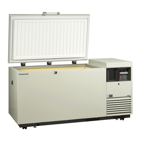
Ultra-Low Temp. Freezer
MDF-394
MDF-393(N)
FILE No.
SANYO Electric Co., Ltd.
Biomedical Business Division
SM9910175
Advertisement
Table of Contents

Related Manuals for Sanyo MDF-393


Summarization of Contents
Specifications
Structural Specifications
Details the physical characteristics and construction of the freezer.
Control Specifications (Microcomputer)
Outlines the parameters and functions of the temperature controller and alarms.
Performance Specifications
Describes the cooling capacity, temperature range, power consumption, and noise level.
Dimensions
Provides detailed diagrams and measurements of the freezer's physical size.
Cooling Unit Parts
Lists and describes the components within the cooling system of the freezer.
Refrigeration Circuit
Illustrates the flow and components of the refrigeration system.
Components on PCB
Identifies and locates the components mounted on the printed circuit boards.
Connections on PCB
Details the wiring connections for various connectors on the control PCB.
Wiring Diagram
Provides a schematic of the electrical connections throughout the freezer.
Circuit Diagram
Presents the electronic circuit schematic for the freezer's control system.
Electric Specifications
Lists the electrical components and their ratings used in the freezer.
Specification of Sensor
Provides temperature and resistance data for the thermistor and Pt1000 sensors.
Control Panel Specifications
Control Panel Keys
Explains the function of each key on the control panel (BUZZER, ALARM TEST, SET, etc.).
Temperature Control Settings
Details how to set and adjust the chamber temperature and its acceptable range.
Key Lock Mode
Explains how to enable or disable the control panel key lock function.
Function Mode Operations
Describes how to access and use various function modes for settings and diagnostics.
Error Codes
Temperature Sensor Errors
Details error codes E01 and E02 related to the temperature sensor and their impact.
Cascade Sensor Errors
Details error codes E03 and E04 for the cascade sensor and their impact.
Filter Sensor Errors
Details error codes E05 and E06 for the filter sensor and related compressor actions.
AT Sensor Errors
Details error codes E07 and E08 for the AT sensor and alarm activations.
Battery Switch Error
Explains error E09 when the battery switch is off or battery is unconnected.
Compressor Abnormal Temperature Error
Details error E10 related to abnormal compressor temperature or fan motor.
Error Code Priority
Lists the priority order for different types of error codes.
Alarms
High Temperature Alarm
Describes conditions and actions for high temperature alarms, including buzzer and remote alarm.
Low Temperature Alarm
Details the low temperature alarm conditions, indicators, and remote alarm behavior.
Power Failure Alarm
Explains the alarm triggered by power interruptions and its recovery behavior.
Filter Alarm
Describes the filter alarm activation, indicators, and buzzer settings.
Other Functions
Auto Return Function
Explains the automatic return to normal display after inactivity in setting modes.
Alarm Resume Time
Describes the function to prevent immediate silencing of alarms and its setting.
Sensor Temperature Display
Details how to display temperatures from various sensors (temp., cascade, filter, AT).
Battery Accumulation Time
Explains how to display and reset battery accumulation time for maintenance.
Condensing Fan Motor Accumulation Time
Details how to display and reset the accumulation time for the condensing fan motor.
Capillary Heater Operation
Describes how to control the capillary heater for preventing oil logging.
ROM Version Display
Explains how to display the current ROM version of the control unit.
Function Mode
Setting High Temperature Alarm
Instructions for setting the high temperature alarm threshold.
Setting Low Temperature Alarm
Instructions for setting the low temperature alarm threshold.
Display Battery Accumulation Time
How to view the battery's accumulated operating time.
Setting Compressor Delay Time
Configuration for delaying compressor startup after power restoration.
Service Code Input
Procedure for entering a service code to access advanced functions.
Temp. Sensor Zero Adjustment
How to calibrate the temperature sensor's zero point.
Cascade Sensor Zero Adjustment
How to calibrate the cascade sensor's zero point.
Display Temperature Sensor Reading
How to view the current reading from the main temperature sensor.
Display Cascade Sensor Reading
How to view the current reading from the cascade temperature sensor.
Display Filter Sensor Reading
How to view the current reading from the filter temperature sensor.
Display AT Sensor Reading
How to view the current reading from the ambient temperature sensor.
Non-Volatile Memory Initialization
Procedure for initializing memory and setting the model code.
Control Capillary Heater
How to manually turn the capillary heater on or off.
Display Power Supply Voltage
How to view the current power supply voltage percentage.
Set Remote Alarm and Buzzer
Configuration for synchronizing remote alarms with buzzer operations.
Alarm Auto Recovery Time Setting
Setting the delay before alarms automatically reset or re-activate.
Display Running Rate
How to view the operational running rate of the unit.
Display ROM Version
How to view the firmware version of the control unit.
Filter Alarm Buzzer Setting
Option to enable or disable the buzzer for filter alarms.
Display Fan Motor Accumulation Time
How to view the accumulated operating time of the condensing fan motor.
Control of Compressor
Differential Temperature Control
Explains compressor operation based on differential temperature settings.
Compressor Cycle Operation
Illustrates compressor behavior during normal cooling cycles.
H Side Compressor Protection
Details protection mechanisms for the high-side compressor.
Filter Sensor Temperature Impact
How filter sensor temperature affects high-side compressor operation.
Compressor Delay Time
Explains compressor startup delay and power failure alarm delay.
Prevention for Oil Logged in Capillary
Capillary Heater Operation Control
Details the forced ON/OFF control of the capillary heater.
Sensor Offset
Temperature Sensor Offset
Specifies the offset value for the main temperature sensor and its function.
Cascade Sensor Offset
Specifies the offset value for the cascade sensor and its function.
Filter Sensor Offset
Specifies the offset value for the filter sensor.
AT Sensor Offset
Specifies the offset value for the AT sensor.
Remote Alarm Terminal
Remote Alarm Terminal Operation
Describes the behavior of the remote alarm contact based on alarm status.
Power Reset Behavior
Settings After Power Reset
Lists the default settings when the unit is reset after a power loss.
Momentary Power Failure Diagnosis
Explains how momentary power failures are diagnosed and their resulting settings.
Lamp, Display and Buzzer Specifications
Control PCB Lamp Operation
Details the meaning of indicator lights on the control PCB.
Display PCB Indicator Lights
Explains the functions of the indicator lamps on the display PCB.
Example Display Readings
Shows sample readings for chamber temp, set temp, sensor offset, function, and error codes.
Buzzer Tone Descriptions
Describes different buzzer tones for alarms and operations.
Parts Layout
Front View Parts Layout
Identifies main components visible from the front of the freezer.
Interior Chamber Components
Locates sensors and other components inside the freezer chamber.
Control Panel Rear Components
Shows the switch PCB and display PCB on the back of the control panel.
Left Side Area Components
Identifies the cover for the Temp. control PCB and related components.
Temp. Control PCB Layout
Shows the Temp. control PCB and its associated power transformer and battery.
Left Side (Top Cover Removed) Parts
Identifies noise filter, electric box, compressors, and fan motor.
Back Side / Remote Alarm Terminal Layout
Shows terminal connections and covers on the back of the unit.
Electric Box Components
Identifies relays, capacitors, and wiring within the electric box.
Test Data
Pull-down Data
Graph showing chamber temperature drop over time to reach target temperature.
Unit Pressure Data
Graphs illustrating high and low-side pressure readings during operation.
Current and Power Consumption
Graph showing power consumption and current draw over time.
Measure Points for Temperature Distribution
Diagrams indicating the locations for measuring temperature distribution inside the chamber.
Amount of Power Consumption
Tables detailing power consumption values under various temperature and voltage conditions.
Chamber Temperature Distribution Graphs
Graphs illustrating temperature variations across the chamber at different settings.
Need help?
Do you have a question about the MDF-393 and is the answer not in the manual?
Questions and answers