Table of Contents
Advertisement
Advertisement
Table of Contents

Related Manuals for Sanyo MDF-394


Summary of Contents for Sanyo MDF-394
- Page 1 INSTRUCTION MANUAL MDF-394 MDF-394AT Ultra-Low Temperature Freezer MDF-394AT...
-
Page 2: Table Of Contents
CONTENTS INTRODUCTION P. 2 PRECAUTIONS FOR SAFE OPERATION P. 3 ENVIRONMENTAL CONDITIONS P. 7 FREEZER COMPONENTS P. 8 Control panel P. 10 INSTALLATION SITE P. 11 INSTALLATION P. 12 START-UP OF UNIT P. 13 CHAMBER TEMPERATURE SETTING P. 14 KEY LOCK FUNCTION P. -
Page 3: Introduction
■ Contact Sanyo sales representative or agent if any page of the manual is lost or page order is incorrect. ■ Contact Sanyo sales representative or agent if any point in this manual is unclear or if there are any inaccuracies. -
Page 4: Precautions For Safe Operation
PRECAUTIONS FOR SAFE OPERATION It is imperative that the user complies with this manual as it contains important safety advice. Items and procedures are described so that you can use this unit correctly and safely. If the precautions advised are followed, this will prevent possible injury to the user and any other person. - Page 5 PRECAUTIONS FOR SAFE OPERATION WARNING Do not use the unit outdoors. Current leakage or electric shock may result if the unit is exposed to rain water. The installation by Only qualified engineers or service personnel should install the unit. unqualified personnel may cause electric shock or fire. Install the unit on a sturdy floor and take an adequate precaution to prevent the unit from turning over.
- Page 6 PRECAUTIONS FOR SAFE OPERATION WARNING Ensure you do not inhale or consume medication or aerosols from around the unit at the time of maintenance. These may be harmful to your health. Never splash water directly onto the unit as this may cause electric shock or short circuit. Never put containers with liquid on the unit as this may cause electric shock or short circuit when the liquid is spilled.
- Page 7 PRECAUTIONS FOR SAFE OPERATION CAUTION Use a dedicated power source (a dedicated circuit with a breaker) as indicated on the rating label attached to the unit. A branched circuit may cause fire resulting from abnormal heating. Connect the power supply plug to the power source firmly after removing the dust on the plug. A dusty plug or improper insertion may cause a heat or ignition.
-
Page 8: Environmental Conditions
ENVIRONMENTAL CONDITIONS This equipment is designed to be safe at least under the following conditions (based on the IEC-61010-1): ■ Indoor use; ■ Altitude up to 2000 m; ■ Ambient temperature 5 C to 40 ■ Maximum relative humidity 80% for temperature up to 31 C decreasing linearly to 50% relative humidity at 40 ■... -
Page 9: Freezer Components
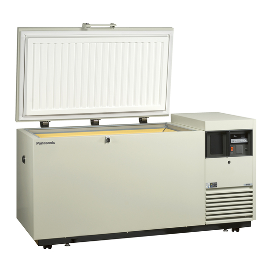
FREEZER COMPONENTS MDF-394 Remote alarm terminal Fixture Rear side... - Page 10 FREEZER COMPONENTS 1. Lock: Turn clockwise to 180 with a key and the outer door is securely locked. 2. Door: Hinged type. The door can be opened in any angle on the way to full open. 3. Magnetic door gasket: Seals the door and prevents leakage of cold air. 4.
-
Page 11: Control Panel
FREEZER COMPONENTS Control panel < MDF-394AT > 1. Alarm buzzer stop key (BUZZER): To stop the alarm from sounding, press this key. Should a further abnormality occur, the buzzer will sound automatically. 2. Filter check lamp (FILTER CHECK): This lamp lights when the condenser filter is clogged. Clean the condenser filter according to page 19 “Cleaning of condenser filter”. -
Page 12: Installation Site
INSTALLATION SITE To operate this unit properly and to obtain maximum performance, install the unit in a location with the following conditions: ■ A location not subjected to direct sunlight Do not install the unit under direct sunlight. Installation in a location subjected to direct sunlight cannot obtain the intended performance. -
Page 13: Installation
INSTALLATION 1. Removing the packaging materials and tapes Remove all transportation packaging materials and tapes. Open the doors and ventilate the unit. If the outside panels are dirty, clean them with a diluted neutral dishwashing detergent. (Undiluted detergent can damage the plastic components. For the dilution, refer to the instruction of the detergent.) After the cleaning with the diluted detergent, always wipe it off with a wet cloth. -
Page 14: Start-Up Of Unit
5. Turn on the battery switch. Note: The battery needs to be replaced about every 3 years. Contact Sanyo sales representative or agent for battery replacement. 6. The alarm buzzer sometimes operates. In this case, stop the buzzer by pressing the alarm buzzer stop key (BUZZER). -
Page 15: Chamber Temperature Setting
CHAMBER TEMPERATURE SETTING Table 1 shows the basic procedure for setting the chamber temperature. Perform key operations in the sequence indicated in the table. The example in the table is based on the assumption that the desired temperature is -75 Note: The unit is set at the factory that the chamber temperature -80 Table 1. -
Page 16: Alarm Temperature Setting
ALARM TEMPERATURE SETTING This unit is provided with the high and low temperature alarm and the temperature at which the alarm is activated is changeable. The following procedure shows the setting of alarm temperature according to the condition below: High temperature alarm: activates at the temperature 5 C higher than the chamber set temperature Low temperature alarm: activates at the temperature 5 C lower than the chamber set temperature... -
Page 17: Setting Of Alarm Resume Time
SETTING OF ALARM RESUME TIME The alarm buzzer is silenced by pressing buzzer stop key (BUZZER) on the control panel during alarm condition (The buzzer stops, but alarm lamp and remote alarm are not silenced.). The buzzer will be activated again after certain suspension if the alarm condition is continued. The suspension time can be set by following the procedure shown in the Table 5 below. -
Page 18: Remote Alarm Terminal
REMOTE ALARM TERMINAL The terminal of the remote alarm is located at rear of the machinery room, upper side of the unit. The alarm is outputted from this terminal. Contact capacity is DC 30 V, 2 A. Contact output: between COM. and N.O. between COM. -
Page 19: Alarms & Safety Functions
ALARMS & SAFETY FUNCTIONS This unit has the alarm and safety functions shown in table below, and also self diagnostic function. Table 6. Alarm and safety function Alarm & safety Situation Indication Buzzer Safety operation If the chamber temperature is higher High temperature than the temperature at which the alarm... -
Page 20: Routine Maintenance
ROUTINE MAINTENANCE WARNING Always disconnect the power supply to the unit prior to any repair or maintenance of the unit in order to prevent electric shock or injury. Ensure you do not inhale or consume medication or aerosols from around the unit at the time of maintenance. -
Page 21: Troubleshooting
Inquire at liquid CO suppliers about cylinder check, adjustment, installation, or move. Note: If the malfunction is not eliminated after checking the above items, or the malfunction is not shown in the above table, contact Sanyo sales representative or agent. -
Page 22: Replacement Of Battery
REPLACEMENT OF BATTERY Location of a nickel-metal-hydride battery This unit is provided a nickel-metal-hydride battery for the power failure alarm. The battery is located in the control box behind the control panel. (Fig. 1) The high voltage components are enclosed in the control box. The cover should be removed by a qualified engineer or a service personnel only to prevent the electric shock. -
Page 23: Disposal Of Unit
DISPOSAL OF UNIT WARNING If the unit is to be stored unused in an unsupervised area for an extended period ensure that children do not have access and doors cannot be closed completely. The disposal of the unit should be accomplished by appropriate personnel. Always remove doors to prevent accidents such as suffocation. - Page 24 The symbol mark and recycling systems described below apply to EU countries and do not apply to countries in other areas of the world. Your SANYO product is designed and manufactured with high quality materials and components which can be recycled and/or reused.
- Page 25 POUR LES UTILISATEURS DE UE Le symbole et les systèmes de recyclage évoqués ci-dessous s'appliquent uniquement aux pays de UE. Votre produit SANYO est conçu et fabriqué avec des composants et des matériaux de hautes qualités qui peuvent être recyclés et/ou réutilisés.
- Page 26 PER UTENTI UE Il simbolo e i sistemi di riciclaggio descritti di seguito si applicano esclusivamente ai paesi dell’UE. Questo prodotto SANYO è stato progettato e realizzato con materiali e componenti di elevata qualità che possono essere riciclati e/o riutilizzati.
- Page 27 Het symbool en de recycleersystemen die hieronder beschreven worden, zijn van toepassing op de landen in de EU en zijn niet van toepassing op landen in andere delen van de wereld. Uw SANYO product is ontworpen en gemaakt met materialen en onderdelen van hoge kwaliteit, die gerecycleerd en opnieuw gebruikt kunnen worden.
-
Page 28: Temperature Recorder For At Type
TEMPERATURE RECORDER for AT type The figure below shows the description of a temperature recorder. The temperature recorder is provided with model AT type. Time Temperature Warning indicator Recording indicator Pen holder lever Door Cartridge Feeding of recording chart 1. Open the door and let down the penholder; level the pen point is apart from the recording chart. 2. - Page 29 The battery for back-up system is discharged when the back-up switch is kept on. ■ The additional recording pen or recording chart is available from Sanyo sales representative or agent. ■ To stop the temperature recorder, remove the dry cell from the temperature recorder. The back-up system can operate without temperature recorder.
-
Page 30: Back-Up System For At Type
CO cylinder to the joint of the back-up system. For this setting, consult with a qualified gas supplier or Sanyo sales representative agent. 2. After setting the liquid CO cylinder, operate the freezer until the chamber temperature reaches the Solenoid valve required level. -
Page 31: Specifications
■ The battery for power failure alarm is an article for consumption. It is recommended that the battery will be replaced about every 3 years. Contact Sanyo sales representative or agent at the time of replacement of the battery for recycling. -
Page 32: Performance
PERFORMANCE Cooling performance C (Ambient temperature; +30 C, no load) Temperature control range -50 to -86 Power source (AC) 220 V, 50 Hz 230 V, 50 Hz 240 V, 50 Hz Rated power consumption 620 W 650 W 680 W Alarm duration 9 hours for power failure Noise level... -
Page 33: Safety Check Sheet
Procedure to be adhered to in order to reduce safety risk indicated in b) below. Date : Signature : Address, Division : Telephone : Product name: Model: Serial number: Date of installation: MDF-394/394AT Ultra-low temperature reezer Please decontaminate the unit yourself before calling the service engineer. - Page 34 7FB6P10150000 (25 September 2008) 5-5, Keihan-Hondori 2-Chome Moriguchi City, Osaka 570-8677 Japan Printed in Japan...
Need help?
Do you have a question about the MDF-394 and is the answer not in the manual?
Questions and answers