Advertisement
Do you have a question about the MDF-U72V and is the answer not in the manual?
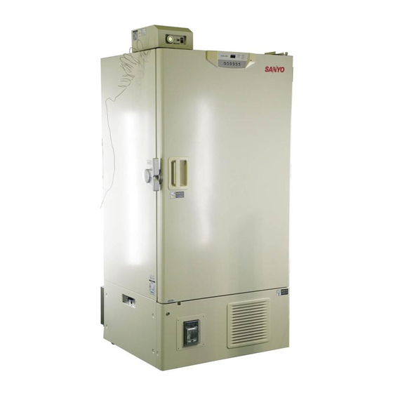
Need to Buy Sanyo Sashmi Freezer. Model : MDF U72V


Need help?
Do you have a question about the MDF-U72V and is the answer not in the manual?
Questions and answers
Need to Buy Sanyo Sashmi Freezer. Model : MDF U72V