Table of Contents
Advertisement
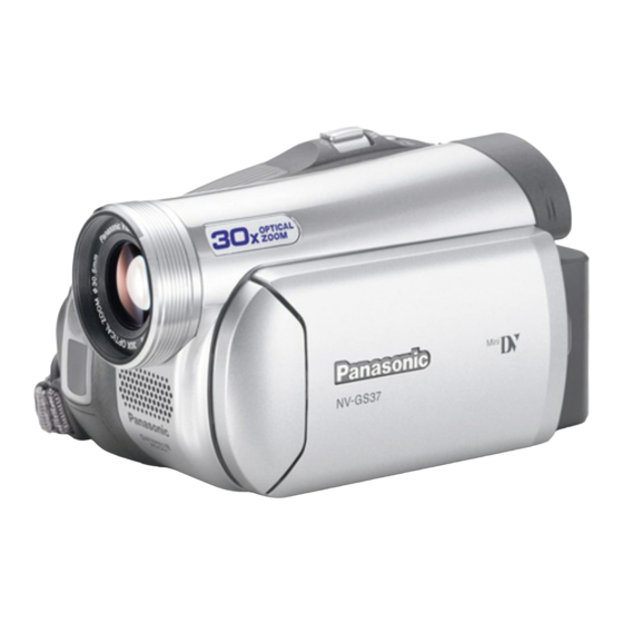
Digital Video Camcorder
NV-GS24EG NV-GS26GK
NV-GS27E NV-GS27EB
NV-GS27EE NV-GS27EF
NV-GS27EG NV-GS27EP
NV-GS27GC NV-GS27GN
NV-GS37E NV-GS37EB
NV-GS37EG NV-GS37EK
NV-GS37EP NV-GS47EE
NV-GS47GC NV-GS57EE
NV-GS57GC NV-GS58GK
Vol. 1
Colours
(S)...................Silver Type
© 2006 Matsushita Electric Industrial Co., Ltd. All
rights
reserved.
distribution is a violation of law.
ORDER NO. VM0602001CE
Unauthorized
copying
and
Advertisement
Table of Contents

Summarization of Contents
Safety Precautions
General Guidelines
Important safety notice for handling the equipment and preventing hazards.
Warning
Prevention of Electro Static Discharge (ESD) to Electrostatically Sensitive (ES) Devices
Techniques to reduce component damage from static electricity.
Caution for AC Cord (VJA0940 type)
Safety information regarding the AC cord and plug for electrical safety.
How to Replace the Lithium Battery
Instructions and warnings for safely replacing the lithium battery.
Service Navigation
Introduction
Purpose of the service manual and how to use it.
About Lead Free Solder (PbF)
Information about lead-free solder, including handling precautions.
Service Mode
Error Display
How the camcorder displays errors and indicates when service is required.
Service Menu
Procedure to enter the service menu and select items for diagnosis.
Service Fixture & Tools
Service Fixture and Tools
Lists specific fixtures and tools required for servicing.
Service Position
How to set up the unit for service using extension cables.
Removal/Installation of F.P.C. From Non ZIF (Zero Insertion Force) Connector
Procedures for removing and installing Flexible Printed Circuits from non-ZIF connectors.
Method for Loading/Unloading of Mechanism
Procedure for manually loading or unloading the mechanism.
EEPROM Data
Caution and procedure for saving EEPROM data before service.
Special Note
Special note regarding electrostatic discharge sensitivity of semiconductor devices.
Disassembly and Assembly Instructions
Cabinet Section
Flowchart for disassembling the cabinet parts to access internal components.
Mechanism Section
Flow-Chart for Disassembly Procedures
Flow chart outlining procedures for mechanism disassembly.
Measurements and Adjustments
Mechanical Adjustment
Procedures for mechanical adjustments, including Envelope Output Adjustment.
Electrical Adjustment and PC Setup
Guidelines for electrical adjustments, USB drivers, COM mode, and PC software setup.
Maintenance
Cleaning Lens, Viewfinder and LCD Panel
Instructions for cleaning optical surfaces and displays.
How to use the DVC Head Cleaning Tape / VFK1451
Procedure for using a DVC head cleaning tape to clean video heads.
Schematic Diagrams
SCHEMATIC DIAGRAM & CIRCUIT BOARD LAYOUT NOTES
Notes and guidelines for interpreting schematic diagrams and circuit board layouts.
FRONT SCHEMATIC DIAGRAM
Schematic diagram for the front section of the camcorder.
LCD BACKLIGHT SCHEMATIC DIAGRAM
Schematic diagram for the LCD backlight circuit.
EVF BACKLIGHT / CASSETTE COVER SCHEMATIC DIAGRAMS
Schematic diagrams for EVF backlight and cassette cover circuits.
CCD / REAR / LCD SW / BATTERY CASE SCHEMATIC DIAGRAMS
Schematic diagrams for CCD, rear, LCD switch, and battery case.
INTERCONNECTION SCHEMATIC DIAGRAM
Diagram showing interconnections between various PCBs and units.
VOLTAGE CHART
Chart listing voltage measurements for specific points.
Printed Circuit Board
FRONT P.C.B.
Component layout for the front printed circuit board.
LCD BACKLIGHT P.C.B.
Component layout for the LCD backlight printed circuit board.
Exploded Views
MAIN PARTS SECTION
Exploded view of the main parts section of the camcorder.
FRONT AND BOTTOM CASE SECTION
Exploded view of the front and bottom case sections.
SIDE CASE R AND LCD SECTION
Exploded view of the side case R and LCD section.
CCD AND LENS SECTION
Exploded view of the CCD and lens section, including lubrication points.
EVF SECTION
Exploded view of the EVF (Electronic Viewfinder) section.
MECHANISM SECTION
Exploded view of the mechanism section, with notes on adjustments.
PACKING PARTS AND ACCESSORIES SECTION
Exploded view of packing parts and accessories.
Replacement Parts Lists
MECHANICAL REPLACEMENT PARTS LIST
List of mechanical replacement parts with part numbers and remarks.
ELECTRICAL REPLACEMENT PARTS LIST
List of electrical replacement parts, including PCBs and components.


Need help?
Do you have a question about the NV-GS27GC and is the answer not in the manual?
Questions and answers