
Related Manuals for LG GR-399


Summarization of Contents
SAFETY PRECAUTIONS
General Safety Instructions
Crucial safety guidelines for servicing to prevent electric shock and injury.
SERVICING PRECAUTIONS
Refrigerant (R600a) Properties and Handling
Details on R600a refrigerant characteristics, safety, and handling requirements.
Installation, Utilities, and Recharging
Guidelines on installation, necessary tools, and refrigerant recharging procedure.
SPECIFICATIONS
Model GR-399 Specifications
Technical details for GR-399, including dimensions, weight, and system components.
Model GR-359 Specifications
Technical details for GR-359, including dimensions, weight, and system components.
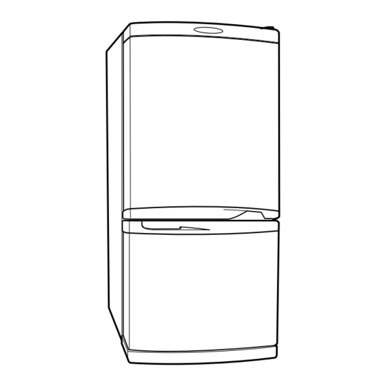
PARTS IDENTIFICATION
Refrigerator Component Layout
Illustrated diagram identifying key parts within the refrigerator compartment.
DOOR REPLACEMENT PROCEDURES
Door Opening Type Adjustment
Instructions and diagrams for changing the door opening direction.
DISASSEMBLY PROCEDURES
Door and Lamp Disassembly
Steps to disassemble doors, door switches, and refrigerator lamps.
Fan and Motor Disassembly
Guide for disassembling the fan and fan motor assembly.
Defrost Control, Damper, and Heater Disassembly
Procedures for disassembling defrost controls, dampers, and heaters.
ADJUSTMENT PROCEDURES
Compressor and PTC-Starter Operation
Explanation of compressor function and PTC starter principles.
PTC-Starter Circuit and Troubleshooting
Details on PTC starter circuit, restarting, and troubleshooting.
CIRCUIT DIAGRAMS
Main Electrical Circuit
Schematic diagram of the primary electrical circuits for the refrigerator.
TROUBLESHOOTING GUIDE
Compressor and Electric Component Issues
Diagnostic steps for compressor and general electric component failures.
Relay Assy (PTC/OLP) Troubleshooting
Procedures for testing and replacing the PTC and OLP relay assembly.
Other Electric Components Troubleshooting
Diagnostic approaches for issues with sensors, switches, and other electrical parts.
Service Diagnosis Chart
Comprehensive chart linking complaints to check points and remedies.
REFRIGERATING CYCLE ANALYSIS
Refrigerating Cycle Troubleshooting
Troubleshooting chart for common refrigerating cycle faults like leakage and clogs.
Refrigerant Leak Detection
Flowchart for identifying and locating refrigerant leaks within the system.
MICOM FUNCTIONS AND PCB EXPLANATION
Function Modes and Operations
Explanation of refrigerator modes (Quick Freezer, Vacation) and door alarm.
Defrosting and Part Operations
Details on defrosting sequence and orderly operation of electric parts.
Self-Test and Function Tests
Procedures for using self-test and function test modes for diagnostics.
ELECTRONIC SYSTEM DESCRIPTION
Electric Circuits Overview
Explanation of power supply, oscillation, and reset circuits.
Sensor and Switch Input Circuits
Details on temperature sensor and switch input circuits and their characteristics.
Temperature Compensation Adjustment
Guide for adjusting freezer temperature compensation via resistance changes.
EXPLODED VIEWS
Exploded View for GR-399
Visual breakdown of the GR-399 model's components for identification.
Exploded View for GR-359
Visual breakdown of the GR-359 model's components for identification.
REPLACEMENT PARTS LISTS
Parts List for GR-399
Detailed list of all replaceable parts for the GR-399 model.
Parts List for GR-359
Detailed list of all replaceable parts for the GR-359 model.
Need help?
Do you have a question about the GR-399 and is the answer not in the manual?
Questions and answers