Table of Contents
Advertisement
Advertisement
Table of Contents

Related Manuals for Lennox CWC 050


Summarization of Contents
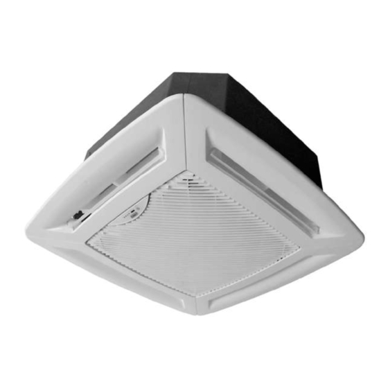
Product Range
Packing Content
Lists the components included in the product packaging.
General Information
Unit Components Overview
Covers Cabinet, Diffuser Panel, Heat Interchange, Fan, and Air Distribution features.
Internal Systems and Electric Circuit
Details internal components, air filter, and electric circuit layout.
Available Options Overview
Lists optional features for the unit.
Specifications
2 Pipes System
Details technical specifications for the 2-pipe system.
Correction Factors for Fan Speed
Lists correction factors for fan speeds to adjust capacity and airflow.
Water Pressure Drop
Provides pressure drop data based on flow rate and glycol percentage.
Electrical Connections
Details wiring requirements and diagrams for power supply and thermostat connections.
Unit Dimensions
Cassette Unit Dimensions
Provides dimensional drawings for the main cassette unit.
Diffuser Panel Dimensions
Shows dimensions and mounting details for the diffuser panel.
Drain Pipework
Condensate Pump Hose & Drain Tube
Illustrates the condensate pump hose, drain tube, and trap requirements.
Installation Method - Positioning and Clearances
Details the initial steps for unit installation positioning and clearances.
Installation Method
Ceiling Cutout and Suspension Rods
Details cutting the ceiling and installing suspension rods with nuts and washers.
Unit Lifting and Securing
Explains how to lift the unit using hanging brackets and secure it to suspension rods.
Leveling and Final Adjustments
Covers checking unit levelness and final tightening of suspension rods.
Control Panel
Electrical Shock Hazard Warning
Warns about electrical shock hazards during service or maintenance.
Access to Electrical Components
Describes how to access electrical components by removing covers.
Electrical Wiring Diagram Reference
Refers to the in-unit diagram for electrical connections.
Installation of Diffuser and Inlet Grille
Mounting Diffuser Panel to Unit
Details the process of mounting the diffuser panel onto the cassette unit.
Display Unit Holder Installation
Explains how to mount the display unit holder.
Air Intake Grille and Filter Assembly
Describes how to attach the air intake grille and filter assembly.
Maintenance
Maintenance Safety Warning
Warns about electrical shock hazards during maintenance.
Cleaning the Air Filter
Provides step-by-step instructions for cleaning the air filter.
Access to Electrical Board
Details how to access the electrical board and PCB.
Maintenance (Continued)
Access to Internal Components & Drip Tray Disassembly
Lists internal components and steps to disassemble the drip tray.
Air Distribution Louvres
Describes how louvres adjust for heating and cooling modes.
Options
Optional Electric Heater Data
Provides technical specifications for optional electric heaters.
Fresh Air Make-Up Installation
Details the installation of a fresh air inlet duct.
Air Supply to Adjacent Room
Explains how to duct air to an adjacent room.
Options (Continued)
Water Control Valve Kits
Details the water control valve kit options.
Auxiliary Drip Tray Installation
Explains the installation and connection of an auxiliary drip tray.
Fault Analysis
Unit Not Operating Troubleshooting
Lists actions to take when the unit is not operating.
Fan Speed Troubleshooting
Provides troubleshooting steps for fan speed issues.
Condensate Overflow Troubleshooting
Lists actions for addressing condensate overflow problems.
Points to Keep in Mind
Safety Icons and Filter Cleaning
Explains safety symbols and provides filter cleaning guidance.
Standard Guidelines and Disclaimers
Outlines standard guidelines, property rights, and disclaimers.
Need help?
Do you have a question about the CWC 050 and is the answer not in the manual?
Questions and answers