Table of Contents
Advertisement
SLV-ED115/ED215/ED313/ED515/ED616/ED815/ED817/
SERVICE MANUAL
1
2
3
4
5
6
7
8
9
0
VIDEO
S MECHANISM
• Refer to the SERVICE MANUAL of VHS MECHANICAL
ADJUSTMENTS VI for MECHANICAL ADJUSTMENTS.
(9-921-647-11)
* The abbreviations of ED115/ED215/ED313/ED515/ED616/ED815/
ED817/ED818/ED915/ED919/EZ111/EZ212/EZ414/EZ715 and EZ717
contained in this service manual are indicated when these models are
common to all their corresponding models as given below.
Abbreviated
ED115
ED215
model name
ED115PS
All model
ED215PS
ED313ME
names
ED215TH
ED313MJ
SLV-
ED313SG
ED818/ED915/ED919/EZ111/EZ212/EZ414/
RMT-V309/V311/V311A/V311B/V311C/V311D/V311E
SLV-ED818
ED515
ED313
ED616
ED815
ED515PS
ED616ME
ED815PS
ED616MJ
ED815TH
ED616SG
ED817
ED818
ED915
ED919
ED817PS
ED818ME
ED915PS
ED919MI
ED817TH
ED818SG
ED915TH
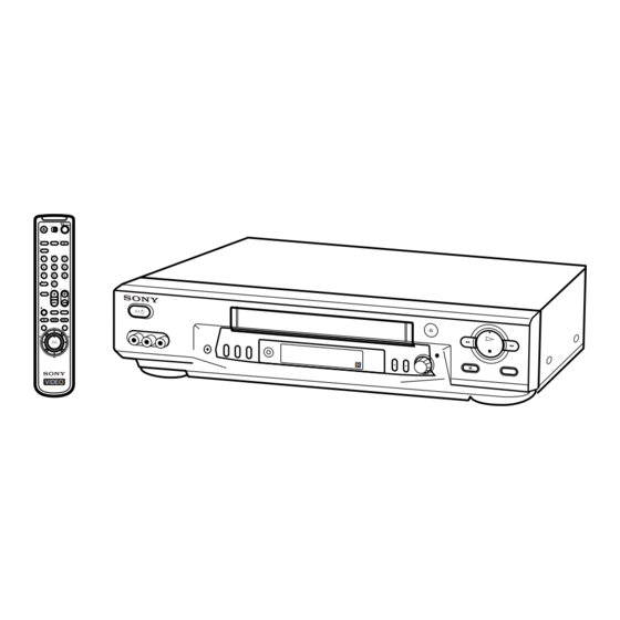
VIDEO CASSETTE RECORDER
EZ715/EZ717
Australian Model
SLV-EZ111AZ/EZ212AZ/EZ414AZ/
EZ715AS/EZ717AS
E Model
SLV-ED115PS/ED215PS/ED515PS/
ED815PS//ED817PS/ED915PS
Hong Kong Model
SLV-ED919MI
ME Model
SLV-ED313ME/ED313MJ/ED313SG/
ED616ME/ED616MJ/ED616SG/
ED818ME/ED818SG
New Zealand Model
SLV-EZ715NZ/EZ717NZ
Thai Model
SLV-ED215TH/ED815TH/ED817TH/
EZ111
EZ212
EZ414
EZ715
EZ111AZ
EZ212AZ
EZ414AZ
EZ715AS
EZ715NZ
ED915TH
EZ717
EZ717AS
EZ717NZ
Advertisement
Table of Contents

Related Manuals for Sony SLV-EZ715


Summarization of Contents
SPECIFICATIONS
SAFETY CHECK-OUT
Important safety checks after repair before releasing the unit.
General
Covers power requirements, consumption, operating temp, dimensions, mass.
1. DISASSEMBLY
2-1. CASE, FRONT PANEL BLOCK ASSEMBLY
Step-by-step guide to disassembling the case and front panel.
2-5. MECHANISM DECK
Guide for removing the VCR's mechanism deck.
2-7. CIRCUIT BOARDS LOCATION
Identifies the location of key circuit boards.
3. BLOCK DIAGRAMS
3-1. OVERALL BLOCK DIAGRAM
High-level block diagram of the VCR system.
3-4. AUDIO BLOCK DIAGRAM
Block diagram illustrating the audio signal path.
SECTION 4 PRINTED WIRING BOARDS AND SCHEMATIC DIAGRAMS
4-1. FRAME SCHEMATIC DIAGRAM
Schematic diagram of the VCR frame.
MA-402 (VIDEO, AUDIO) SCHEMATIC DIAGRAM
Schematic for the video and audio sections of MA-402.
MA-402 (SERVO CONTROL) SCHEMATIC DIAGRAM
Schematic for the servo control section of MA-402.
SECTION 5 INTERFACE, IC PIN FUNCTION DESCRIPTION
5-1. SYSTEM CONTROL – VIDEO BLOCK INTERFACE (MA-402 BOARD IC101)
Pin functions for video interface IC.
5-3. SYSTEM CONTROL – MECHANISM BLOCK INTERFACE (MA-402 BOARD IC101)
Pin functions for mechanism block interface IC.
SECTION 6 ERROR CODE
Table 6-1. Error Codes
Lists error codes and their descriptions.
Table 6-2. Mode Codes in Case of Error
Lists mode codes and their descriptions.
SECTION 7 ADJUSTMENTS
7-1. MECHANICAL ADJUSTMENTS
Refers to another manual for mechanical adjustments.
7-2. ELECTRICAL ADJUSTMENTS
Electrical adjustments for the VCR.
2-2. POWER SUPPLY ADJUSTMENT
2-2-1. Power Supply Check
Verifies power supply voltages against specifications.
2-3. SERVO SYSTEM ADJUSTMENT
2-3-1. RF Switching Position Adjustment (MA-402 BOARD)
Adjusts tape playback interval for interchangeability.
2-4. AUDIO SYSTEM ADJUSTMENTS
2-4-1. Hi-Fi Audio System Adjustment
Hi-Fi audio specific adjustments.
2-4-2. Normal Audio System Adjustment
Adjustments for normal audio system.
3. Overall Level Characteristic and Distortion Factor Check
4. Overall S/N Check
Confirms Signal-to-Noise ratio.
2-5. TUNER SYSTEM ADJUSTMENT
2-5-1. Separation Adjustment
Adjusts Lch/Rch audio signal separation.
SECTION 8 REPAIR PARTS LIST
8-1. EXPLODED VIEWS
General overview of parts breakdown.
8-1-1. FRONT PANEL AND UPPER CASE SECTION
Exploded view of front panel and upper case parts.
8-1-3. MECHANISM DECK SECTION-1
Exploded view of mechanism deck parts, section 1.
Need help?
Do you have a question about the SLV-EZ715 and is the answer not in the manual?
Questions and answers