
Related Manuals for Potterton Paramount 60


Summarization of Contents
Paramount 40 Dimensions and Data
Fig 1 - General Data and Dimensions Paramount 40
Diagram and key specifications for the Paramount 40 model.
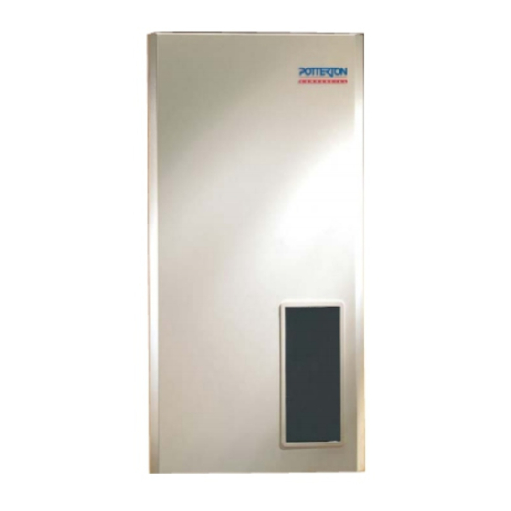
Paramount 60 & 80 Dimensions and Data
Fig 2 - General Data and Dimensions Paramount 60 & 80
Diagram and key specifications for the Paramount 60 and 80 models.
Technical Specifications Overview
Table 1 - Technical Data
Comprehensive technical data for all Paramount boiler models.
General Safety and Installation Requirements
General Safety Precautions
Important safety guidelines for boiler installation and operation.
Boiler Usage and Installation Standards
Information on boiler capabilities and adherence to installation standards.
Boiler Protection and Combustion Air
Corrosion, Frost Protection, and Water Quality
Maintaining boiler integrity through proper water and protection measures.
Combustion Air Requirements
Ensuring adequate and clean air supply for combustion.
Clearances in Wet Rooms
Specific installation clearances for bathrooms and shower rooms.
Protective Zones and Installation Details
Installation in Protective Zones
Guidelines for installing the boiler in protective zones as per standards.
Hydraulic System Applications (Part 1)
Application Example 1a: Single Pumped Circuit
Diagram for a single pumped heating circuit with control modules.
Application Example 1d: Single Pumped Circuit with Primary Loop
Diagram for a single pumped heating circuit with primary loop.
Hydraulic System Applications (Part 2)
Application Example 2a: Mixed Circuits
Diagrams for mixed heating circuits with various control options.
Application Example 2b: Mixed Circuit with Primary Loop
Diagrams for mixed heating circuits with primary loop and controls.
Hydraulic Setup and Flue Connection
Hydraulic Diagram Settings
Settings required for various hydraulic system configurations.
System Filling and Flue Installation
Procedures for filling the system and installing the flue pipe.
Flue Options and Installation Guidance
Paramount Flue Configuration Options
Various flue types and their configurations for Paramount boilers.
Flue Installation Details and Bends
Specific instructions for flue pipe installation and impact of bends.
Gas and Electrical Connection Procedures
Gas Connection Requirements
Factory settings, supply pressure, and CO2 content for gas connection.
Electrical Connection Details
Supply voltage, polarity, cable lengths, and safety for electrical connections.
Boiler Start-Up and Troubleshooting
Start-Up Procedures and Checklist
Steps for initial boiler operation and commissioning.
Fault Diagnosis and Remedies
Common problems and remedies for boiler start-up and operation.
Control Panel and Commissioning Process
Control Panel Components Overview
Identification and function of elements on the boiler's control panel.
Commissioning Steps and Fault Indicators
Procedures for setting up the boiler and interpreting fault displays.
Gas/Air Ratio Control and Adjustment
Gas/Air Ratio Control
Adapting gas supply to air supply for optimal combustion.
Gas Valve Setting and CO2 Adjustment
Adjusting gas valve for correct CO2 levels and burner performance.
Injector Pressure and Boiler Control Signals
Injector Pressure Guide Values
Recommended injector pressures for different gas types and loads.
0-10V DC Boiler Control Input
Using an analog signal to control boiler temperature directly.
Operating Modes and System Configuration
Injector Pressure Guide Values (Full Load)
Guide values for injector pressure at full load for various models.
Operating Modes with Outdoor Sensor
How the boiler operates with different control modules and sensors.
Checking and Modifying Boiler Parameters
Navigating Boiler Display Modes
How to access and navigate different display and parameter levels.
Modifying Boiler Parameters (P0-P6)
Procedures for changing adjustable parameters (P0-P6).
Parameter and Fault Code Reference
Display and Parameter Values
Descriptions of general, temperature, and process parameters.
Fault Code Explanations and Remedies
Explanations of fault codes and their remedies.
Heating Engineer Adjustment Table
Parameter Adjustment Procedure
Step-by-step guide for adjusting system-dependent parameters.
Key Adjustment Parameters (RRG/HKM)
Overview of important parameters for RRG and HKM control modules.
System Configuration and Input/Output Settings
System Volume and Heating Curve Settings
Parameters for system volume, Delta T limits, and heating curve settings.
Programmable Inputs and Outputs Configuration
Configuration of inputs (F2) and outputs (M5) for special functions.
Adjustment Table Explanations
Parameter Explanations (TkSnorm, TuebBw)
Detailed explanations of specific heating and hot water adjustment parameters.
Summer/Winter Changeover Function
How the automatic summer/winter changeover works.
Heating Curve and Burner Adjustments
Adjusting the Heating Curve
How to adjust heating curves based on system type and sensors.
Burner Input Power Settings
Setting minimum and maximum burner input power (kW).
Special Functions and System Settings
Minimum Burner Pause and Delay Times
Settings for burner pause time and start-up delay.
Modem, Door Veil and Programmable Outputs
Configuration of modem, door veil and output M5 functions.
System Settings and Adjustment Codes
Frost Protection and Header Functions
Bit settings for frost protection and header pump functions.
Building Type and Pump Control Settings
Settings for building type and heating circuit pump control.
Advanced Functions and Output Assignments
Output Control and Special Function Settings
Setting burner output and specific functions like modem or door veil.
Programmable Output M5 Functions
Detailed assignment of functions to the programmable output M5.
Analogue Inputs and System Status
Temperature and Output Setpoint Inputs
Configuring analogue inputs for temperature and output setpoints.
Heat Demand and System Status Monitoring
Defining heat demand for pumps and monitoring system status.
Operating Modes and Emergency Functions
Heating and Frost Protection Modes
Various operating modes including quick heat-up, frost protection, and anti-legionnaires.
Chimney Sweep and Emergency Operation
Using chimney sweep function and actions during component failure.
Heating Circuit and Room Control Modules
Heating Circuit Module HKM Overview
Description and operation of the HKM module.
Room Control Module RRG Features
Features and operation of the RRG room control module.
Module Operations and Service Procedures
HKM and RRG Module Operations
How to operate the HKM and RRG modules, including error messages.
Boiler Service and Cleaning
Procedures for cleaning the heat exchanger, burner, and condensate trap.
Boiler Component Views (Paramount 40)
Paramount 40 Boiler Components
Diagram identifying key components of the Paramount 40 boiler.
Boiler Component Views (Paramount 60/80)
Paramount 60 & 80 Boiler Components
Diagram identifying key components of the Paramount 60 and 80 boilers.
Heat Exchanger Removal and Cleaning
Heat Exchanger Removal Procedure
Step-by-step instructions for removing the heat exchanger.
Air Vent Removal
Instructions for removing the air vent.
Control Centre Functions and Operation
Ignition and Ionisation Electrode Function
Ensuring proper function of ignition and ionisation electrodes.
Control Centre Operating Phases
Table detailing the various operating phases of the control centre.
Fault Message Reference Guide
Fault Message Codes and Explanations
List of fault codes, their descriptions, and possible causes.
Paramount 40/60 Wiring Diagram
Wiring Diagram Legend and Components
Key to symbols and list of components in the wiring diagram.
Paramount 80 Wiring Diagram
Wiring Diagram Legend and Components
Key to symbols and list of components in the wiring diagram.
Boiler Casing and Internal Components
Paramount 40-80 Casing Exploded View
Exploded view of the boiler casing and main internal parts.
Paramount 40 Boiler and Burner Assembly
Paramount 40 Boiler and Burner Exploded View
Exploded view of the boiler and burner assembly for the Paramount 40.
Paramount 40 Pipework Assembly
Paramount 40 Pipework Exploded View
Exploded view of the pipework components for the Paramount 40.
Paramount 60/80 Boiler and Burner Assembly
Paramount 60/80 Boiler and Burner Exploded View
Exploded view of the boiler and burner assembly for the Paramount 60/80.
Paramount 60/80 Pipework Assembly
Paramount 60/80 Pipework Exploded View
Exploded view of the pipework components for the Paramount 60/80.
Spares Listings - Casing and Boiler/Burner
Casing Spare Parts
List of spare parts for the boiler casing.
Boiler and Burner Spare Parts
List of spare parts for the boiler and burner assembly.
Spares Listings - Pipework and Controls
Pipework Spare Parts
List of spare parts for the boiler pipework.
Controls Spare Parts
List of spare parts for the boiler controls and modules.
Spares Listings - Miscellaneous Components
Miscellaneous Spare Parts
List of miscellaneous spare parts including sensors and wiring.
Commissioning Report Form
Boiler and Burner Specifications
Fields for recording boiler and burner specifications during commissioning.
Pre-Commissioning Checks
Checklist for essential checks before boiler commissioning.
Operational Checks and System Checklist
Operational Safety Checks
Safety checks to perform during operation.
Boiler and System Checklist
Comprehensive checklist for boiler and system components.
Unit Conversion Table
Heat, Fuel, Pressure, Length Conversions
Conversion factors for heat, fuel, pressure, and length units.
Volume, Area, Flow, Temperature Conversions
Conversion factors for volume, area, flow rate, and temperature.
Potterton Commercial Contact Information
Sales and Technical Support
Contact details for sales and technical enquiries.
Service Offices and Spares
Information on service locations and spare parts availability.
Need help?
Do you have a question about the Paramount 60 and is the answer not in the manual?
Questions and answers