Table of Contents
Advertisement
HCD-GTR6/GTR6B/GTR7/GTR8/GTR8B
SERVICE MANUAL
Ver. 1.0 2009. 05
• HCD-GTR6/GTR7/GTR8
are the tuner, CD and
amplifi er section in
MHC-GTR6/GTR7/GTR8
• HCD-GTR6B/GTR8B
are the tuner, deck, CD and
amplifi er section in
MHC-GTR6/GTR7/GTR8
AUDIO POWER SPECIFICATION
Amplifi er section
MHC-GTR8 (HCD-GTR8/HCD-GTR8B)
The following are measured at
Mexican model:
AC 127 V, 60 Hz
Other models:
AC 120, 220, 240 V, 50/60 Hz
Front/Surround speaker
210 W + 210 W (at 6 Ω, 1 kHz, 1% THD,
Power Output (rated):
at LINK MODE)
Front speaker
RMS output power (reference):
280 W + 280 W (per channel at 8 Ω,
1 kHz, 10% THD)
Surround speaker
RMS output power (reference):
110 W + 110 W (per channel at 24 Ω,
1 kHz, 10% THD)
Subwoofer
RMS output power (reference):
160 W + 160 W (per channel at 6 Ω,
100 Hz, 10% THD)
9-890-515-01
Sony Corporation
2009E08-1
Audio & Video Business Group
© 2009. 05
Published by Sony EMCS (Malaysia) PG Tec
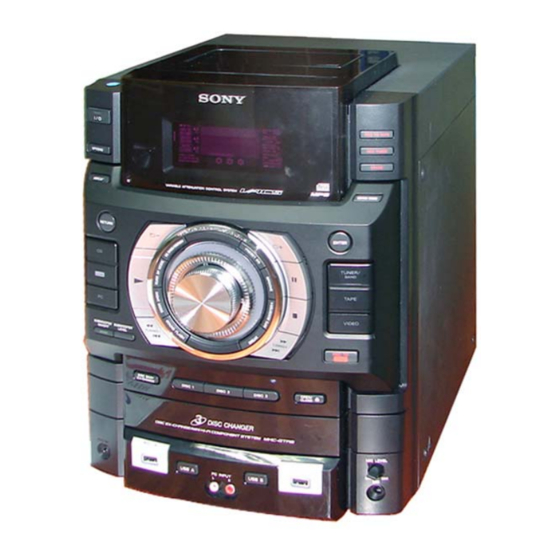
Photo : HCD-GTR8B (E Model)
CD
Section
Tape Deck Section
only for HCD-GTR6B/GTR8B
SPECIFICATIONS
HCD-GTR6/GTR6B/GTR7/GTR8/GTR8B
HCD-GTR6/GTR6B/GTR7/GTR8/GTR8B
Model Name Using Similar Mechanism
CD Mechanism Type
Optical Pick-up Name
Model Name Using Similar Mechanism
Tape Mechanism Type
MHC-GTR7 (HCD-GTR7)
The following are measured at
Mexican model:
AC 127 V, 60 Hz
Other models:
AC 120, 220, 240 V, 50/60 Hz
Front/Surround speaker
215 W + 215 W (at 6 Ω, 1 kHz, 1% THD, at LINK MODE)
Power Output (rated):
Front speaker
RMS output power (reference):
285 W + 285 W (per channel at 8 Ω, 1 kHz, 10% THD)
Surround speaker
RMS output power (reference):
Subwoofer
RMS output power (reference):
COMPACT DISC DECK RECEIVER
E Model
Australian Model
HCD-GTR6B/GTR8B
NEW
CDM74HF-DVBU101//M
KHM-313CAB/C2NP
HCD-GTX777/GTX787/GTX888
CFP42608
110 W + 110 W (per channel at 24 Ω,
1 kHz, 10% THD)
210 W (at 8 Ω, 100 Hz, 10% THD)
– Continued on next page –
1
Advertisement
Table of Contents

Related Manuals for Sony HCD-GTR8


Summarization of Contents
SPECIFICATIONS
AUDIO POWER SPECIFICATION
Detailed audio power output specifications for different models and speakers.
SPECIFICATIONS (Continued)
MHC-GTR6/GTR6B Specifications
Technical specs for MHC-GTR6/GTR6B, including USB, disc, tape, and tuner sections.
Service and Repair Precautions
Component Handling and Safety Notes
Guidelines for chip component replacement, unleaded solder, and laser diode safety.
Model Identification
Model Number Label and Abbreviation Key
Information on identifying models and understanding regional abbreviations.
SECTION 1 DISASSEMBLY
General Disassembly Procedures
Overview of the disassembly process, listing major sections and their order.
SECTION 1 DISASSEMBLY (Continued)
Step-by-Step Component Disassembly
Detailed procedures for removing various components and boards from the unit.
SECTION 2 TEST MODE
System Test Modes Overview
Introduction to various test modes like GC, MC, Cold Reset, and VACS.
SECTION 2 TEST MODE (Continued)
Specific Test Mode Procedures
Detailed instructions for CD Ship, Tray Lock, VACS Display, Meter Aging, and Error Code checks.
SECTION 3 MECHANICAL ADJUSTMENTS
Adjustment Precautions and Torque Measurement
Guidelines for mechanical adjustments, including cleaning and torque specifications.
SECTION 4 ELECTRICAL ADJUSTMENTS
Tuner and Deck Electrical Adjustments
Procedures for FM tune level check and record/playback head azimuth adjustment.
SECTION 4 ELECTRICAL ADJUSTMENTS (Continued)
Playback Head Azimuth Adjustment Details
Detailed steps and waveforms for playback head azimuth adjustment.
SECTION 5 DIAGRAMS
Block Diagrams Overview
Introduction to block diagrams illustrating system sections like USB, RF/Servo, and Tape/Tuner.
SECTION 5 DIAGRAMS (Continued)
RF/SERVO and Main Section Block Diagrams
Block diagrams detailing the RF/Servo, Main, and AMP/Subwoofer sections.
SECTION 5 DIAGRAMS (Continued)
Tape/Tuner and AMP/Subwoofer Block Diagrams
Block diagrams for Tape/Tuner and AMP/Subwoofer sections.
SECTION 5 DIAGRAMS (Continued)
Main and Display/Power Block Diagrams
Block diagrams for the Main and Display/Power sections of the system.
SECTION 5 DIAGRAMS (Continued)
AMP/Subwoofer and Display/Power Block Diagrams
Block diagrams detailing the AMP/Subwoofer and Display/Power sections.
SECTION 5 DIAGRAMS (Continued)
Display/Power Section Block Diagram
Block diagram focusing on the display driver, power supply, and control circuits.
SECTION 5 DIAGRAMS (Continued)
Circuit Boards Location and Diagram Notes
Diagrams showing board locations and explanations of schematic/wiring diagram conventions.
Waveform Analysis
DMB19 Board and Main Board Waveforms
Oscilloscope waveforms for key test points on DMB19 and Main boards during CD playback.
PRINTED WIRING BOARD — DISPLAY BOARD —
Display Board Component Layout
Printed wiring diagram showing component placement on the display board.
SCHEMATIC DIAGRAM — DISPLAY BOARD —
Display Board Circuit Schematic
Detailed circuit schematic for the display board.
PRINTED WIRING BOARDS — DMB19 BOARD —
DMB19 Board Layout (Side A)
Printed wiring diagram for the DMB19 board, component side A.
SCHEMATIC DIAGRAM — DMB19 BOARD (1/4) —
DMB19 Board Schematic (Part 1/4)
Circuit schematic for the DMB19 board, covering specific sections.
SCHEMATIC DIAGRAM — DMB19 BOARD (2/4) —
DMB19 Board Schematic (Part 2/4)
Circuit schematic for the DMB19 board, detailing optical pick-up interface.
SCHEMATIC DIAGRAM — DMB19 BOARD (3/4) —
DMB19 Board Schematic (Part 3/4)
Circuit schematic for the DMB19 board, focusing on servo control logic.
SCHEMATIC DIAGRAM — DMB19 BOARD (4/4) —
DMB19 Board Schematic (Part 4/4)
Circuit schematic for the DMB19 board, showing motor drivers and interface signals.
PRINTED WIRING BOARD — FRONT BOARD —
Front Board Component Layout
Printed wiring diagram showing component placement on the front board.
SCHEMATIC DIAGRAM — FRONT BOARD —
Front Board Circuit Schematic
Circuit schematic for the front board, including power amplifiers.
SECTION 5 DIAGRAMS (Continued)
5-17. PRINTED WIRING BOARD — MAIN BOARD —
Printed wiring diagram showing component placement on the main control board.
SECTION 5 DIAGRAMS (Continued)
5-18. SCHEMATIC DIAGRAM — MAIN BOARD (1/5) —
Circuit schematic for the main board, covering system control and memory interfaces.
SECTION 5 DIAGRAMS (Continued)
5-19. SCHEMATIC DIAGRAM — MAIN BOARD (2/5) —
Circuit schematic for the main board, detailing tape mechanism and audio input switching.
SECTION 5 DIAGRAMS (Continued)
5-20. SCHEMATIC DIAGRAM — MAIN BOARD (3/5) —
Circuit schematic for the main board, showing headphone output and audio processing.
SECTION 5 DIAGRAMS (Continued)
5-21. SCHEMATIC DIAGRAM — MAIN BOARD (4/5) —
Circuit schematic for the main board, illustrating pre-amplifier and relay circuits.
SECTION 5 DIAGRAMS (Continued)
5-22. SCHEMATIC DIAGRAM — MAIN BOARD (5/5) —
Circuit schematic for the main board, covering power supply regulation and control signals.
PRINTED WIRING BOARDS — MIC CD AND MIC RV BOARD —
MIC CD and MIC RV Board Layouts
Printed wiring diagrams for the MIC CD and MIC RV circuit boards.
SCHEMATIC DIAGRAM — MIC CD AND MIC RV BOARD —
MIC CD and MIC RV Board Schematics
Circuit schematics for the MIC CD and MIC RV boards.
PRINTED WIRING BOARD — STR AND CD_SW BOARD —
STR and CD_SW Board Layouts
Printed wiring diagrams for the STR and CD_SW circuit boards.
SCHEMATIC DIAGRAM — STR AND CD_SW BOARD —
STR and CD_SW Board Schematics
Circuit schematics for the STR and CD_SW boards.
PRINTED WIRING BOARD — TRANS AND SUB TRANS BOARD —
TRANS and SUB TRANS Board Layouts
Printed wiring diagrams for the TRANS and SUB TRANS circuit boards.
SCHEMATIC DIAGRAM — TRANS AND SUB TRANS BOARD —
TRANS and SUB TRANS Board Schematics
Circuit schematics for the TRANS and SUB TRANS boards.
PRINTED WIRING BOARD — SUBWOOFER BOARD —
SUBWOOFER Board Layout
Printed wiring diagram for the subwoofer board.
SCHEMATIC DIAGRAM — SUBWOOFER BOARD —
SUBWOOFER Board Schematic
Circuit schematic for the subwoofer board.
PRINTED WIRING BOARDS — HEADPHONE AND USB CD BOARD —
HEADPHONE and USB CD Board Layouts
Printed wiring diagrams for the headphone and USB CD boards.
SCHEMATIC DIAGRAM — HEADPHONE AND USB CD BOARD —
HEADPHONE and USB CD Board Schematics
Circuit schematics for the headphone and USB CD boards.
PRINTED WIRING BOARDS — HUB BOARD —
HUB Board Layouts
Printed wiring diagrams for the HUB board.
SCHEMATIC DIAGRAM — HUB BOARD —
HUB Board Schematic
Circuit schematic for the HUB board.
PRINTED WIRING BOARDS — DRIVE BOARD —
Drive Board Layouts
Printed wiring diagrams for the drive boards.
SCHEMATIC DIAGRAM — DRIVE BOARD —
Drive Board Schematics
Circuit schematics for the drive boards.
IC Block Diagrams
DMB19 Board IC Block Diagrams
Block diagrams for IC107 and IC201 on the DMB19 board.
IC Diagrams (DMB19 Board)
IC4601 and IC4602 Diagrams
Block diagrams for PCM1808PWR (IC4601) and CS4335-KSZR (IC4602) ICs.
IC Diagrams (HUB Board & Main Board Op-Amps)
IC1500 HUB Board and NJM4558 Series Diagrams
Block diagrams for IC1500 (HUB) and NJM4558 series ICs (MAIN).
IC Diagrams (Main Board)
IC400 and IC675 Diagrams
Block diagrams for IC400 (Input Selector) and IC675 (EEPROM).
IC Diagrams (Subwoofer & Drive Boards)
IC800, IC701, IC712 Diagrams
Block diagrams for subwoofer power amp (IC800) and motor drivers (IC701, IC712).
MAIN BOARD IC500 SYSTEM CONTROL Pinout
IC500 System Control Pinout (Part 1)
Detailed pinout and description for IC500 system control IC (Pins 1-32).
MAIN BOARD IC500 SYSTEM CONTROL Pinout (Continued)
IC500 System Control Pinout (Part 2)
Detailed pinout and description for IC500 system control IC (Pins 33-100).
SECTION 6 EXPLODED VIEWS
6-1. MAIN SECTION Exploded View and Parts
Exploded view diagram and parts list for the main section of the unit.
SECTION 6 EXPLODED VIEWS (Continued)
6-2. BACK PANEL SECTION Exploded View and Parts
Exploded view diagram and parts list for the back panel section.
6-3. FRONT PANEL SECTION (1) Exploded View
Front Panel Section (1) Parts List and Diagram
Exploded view and part list for the first part of the front panel assembly.
6-4. FRONT PANEL SECTION (2) Exploded View
Front Panel Section (2) Parts List and Diagram
Exploded view and part list for the second part of the front panel assembly.
6-5. CHASSIS SECTION Exploded View
Chassis Section Parts List and Diagram
Exploded view diagram and parts list for the chassis section.
6-6. CD MECHANISM SECTION (1) Exploded View
CD Mechanism Section (1) Parts List and Diagram
Exploded view diagram and parts list for CD mechanism section 1.
6-7. CD MECHANISM SECTION (2) Exploded View
CD Mechanism Section (2) Parts List and Diagram
Exploded view diagram and parts list for CD mechanism section 2.
SECTION 7 ELECTRICAL PARTS LIST
CD SW BOARD and DISPLAY BOARD Components
List of components for CD SW and Display boards, including switches, capacitors, connectors, diodes.
SECTION 7 ELECTRICAL PARTS LIST (Continued)
DISPLAY DMB19 BOARD Components
List of components for Display and DMB19 boards, including switches and capacitors.
DMB19 DRIVER FRONT Parts List
DMB19 Board Components
List of resistors, ICs, transistors, and connectors for the DMB19 board.
DMB19 DRIVER FRONT Parts List (Continued)
Driver/Front Board Components
List of composition circuits, vibrators, capacitors, connectors, diodes, and ICs for driver/front boards.
FRONT Parts List
Front Board Transistors, Resistors, and Diodes
List of transistors, resistors, and diodes specific to the front board.
HEADPHONE HUB LED Parts List
Headphone and HUB Board Components
List of capacitors, ICs, resistors, and connectors for headphone and HUB boards.
MAIN Board Parts List (Capacitors)
MAIN Board Capacitors (Part 1)
List of capacitors used on the main board.
MAIN Board Parts List (Capacitors Continued)
MAIN Board Capacitors (Part 2)
Continuation of the main board capacitor list.
MAIN Board Parts List (Connectors, Diodes, ICs)
MAIN Board Connectors, Diodes, ICs, Jacks
List of connectors, diodes, ICs, and jacks for the main board.
MAIN Board Parts List (Transistors, Coils, Resistors Part 1)
MAIN Board Transistors and Coils
List of transistors and coils for the main board.
MAIN Board Resistors (Part 1)
List of resistors for the main board.
MAIN Board Parts List (Resistors Part 2)
MAIN Board Resistors (Part 2)
Continuation of the main board resistor list.
MAIN Board Parts List (Resistors Part 3)
MAIN Board Resistors (Part 3)
Further listing of resistors used on the main board.
MAIN Board Parts List (Resistors Part 4)
MAIN Board Resistors (Part 4)
Final listing of resistors used on the main board.
MIC CD Parts List
MIC CD Board Components
List of resistors, capacitors, and ICs for the MIC CD board.
Board-Specific Parts Lists (MIC RV, MOTOR, SENSOR, STR)
MIC RV, MOTOR, SENSOR, STR Components
Lists of diodes, ICs, capacitors, resistors for specific boards.
STR SUBTRANS SUBWOOFER Parts List
STR, SUBTRANS, SUBWOOFER Board Components
List of resistors, capacitors, connectors, diodes, switches, transformers, transistors.
SUBWOOFER SW TRANS USB CD Parts List
SUBWOOFER, SW, TRANS, USB CD Components (Part 1)
List of capacitors, connectors, diodes, ICs, jumpers, coils, transistors, resistors.
SUBWOOFER SW TRANS USB CD Parts List (Continued)
SUBWOOFER, SW, TRANS, USB CD Components (Part 2)
Continuation of parts list for fuses, holders, transistors, resistors, and connectors.
MISCELLANEOUS Parts List
Miscellaneous Items List
List of miscellaneous items like switches, mecha deck, wires, fuses, motors.
REVISION HISTORY
Revision Log
Record of revisions made to the service manual.
Need help?
Do you have a question about the HCD-GTR8 and is the answer not in the manual?
Questions and answers