
Related Manuals for AND OP06


Summarization of Contents
Compliance
Compliance with FCC Rules
Explains compliance with FCC rules for radio frequency energy emitted by the equipment.
Compliance with European Directive
Details appliance compliance with EMC and Low Voltage Directives for electrical equipment.
Installation and Precautions
Installation and Precautions
General advice on handling and operating the weighing indicator safely and correctly.
Power Supply
Guidance on using AC adapters and batteries for powering the indicator.
Load Cell Setup
Covers connecting load cells, adjusting output voltage, and verifying input sensitivity.
Option Installation
Guides on installing optional interface boards and the display stand.
Description of Panels and Symbols
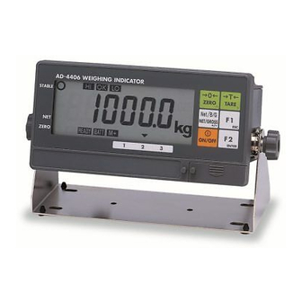
Front Panel Description
Details the layout and functions of the front panel controls and indicators.
Rear Panel Description
Describes the connectors and components located on the rear panel.
Other Displays and Symbols
Explains various display messages and symbols used by the indicator.
Accessories
Lists the included accessories supplied with the weighing indicator.
Calibration
Calibration Modes Overview
Outlines calibration functions like setting ranges, zero/span, and linearization.
Calibration Procedure
Step-by-step guide to calibrate the weighing instrument for accuracy.
Weighing Range Configuration
How to select and set single or dual weighing ranges for the scale.
Digital Linearization
Method to correct linearity deviations using defined weighing points.
Gravity Compensation
Function to adjust for gravity variations between calibration and installation locations.
Calibration Error Codes
Lists and explains error codes encountered during the calibration process.
Functions
Changing Function Settings
How to access and modify F-functions and CF-functions for indicator settings.
F-Functions
Detailed parameters for digital filter, zero tracking, stability, and display settings.
CF-Functions
Configuration parameters for zero range, tare, overload handling, and unit digits.
Accumulation
Preparation and Specification
Steps to set up the accumulation function, including CF08 and F20/F21 settings.
Display and Operation
How to view, undo, clear, and initialize accumulated data.
Comparison
Weight Check Modes
Compares weight against upper/lower limits or 5-stage criteria (HiHi, Hi, OK, Lo, LoLo).
Setting Comparison Conditions
Defines comparison logic and sets limit values for weight check modes.
Setpoint and Batch Comparison
Acquires target weight using sequences, including simple batch operations.
Hold Function
Setting the Hold Functions
Details methods for starting averaging and setting hold parameters (F27, F28).
RS-232C Interface (OP-04, OP-05, OP-08)
Specifications
Technical specifications for the RS-232C serial interface, including transmission and connector details.
Data Format
Describes the structure and format of serial data output based on F34 and F35 settings.
Command Format
Details the commands used to control the indicator via serial interface, including data requests.
UFC Command
Universal Flexi Coms function for customizing serial data output format freely.
RS-422/RS-485, Relay Output (OP-03)
Pin Connections
Details the pinout for RS-422/RS-485 communication and relay output terminals.
Circuit Diagram
Illustrates the electrical connections for the RS-422/RS-485 interface and relay outputs.
Relay Output & Control Input (OP–05)
Pin Connections
Shows the pinout for relay outputs and control input terminals.
Circuit Diagram
Electrical circuit diagram for relay outputs and control inputs.
4-20 mA Analog Output (OP-07)
Specifications
Technical specifications for the 4-20 mA analog output option.
Settings
Configuration parameters (F30-F33) for setting the analog output.
Current Loop Output (OP-08)
Pin Connections
Details the pinout for current loop output and associated terminals.
Circuit Diagram
Electrical circuit diagram for current loop output and control functions.
Data Format
Describes the fixed data format for current loop output.
Specifications
Analog Input & A/D Conversion
Specifications for signal input, load cell excitation, and analog-to-digital conversion.
Digital Section
Specifications for the display, character height, state indicators, and units.
Interface Specifications
Details on RS-232C, RS-422/485, Current Loop, Analog, and Control input interfaces.
General Specifications
Information on power supply, operating temperature, humidity, mass, and accessories.
18.1. Dimensions
Provides physical dimensions and panel cut-out information for the indicator.
Need help?
Do you have a question about the OP06 and is the answer not in the manual?
Questions and answers