Table of Contents
Advertisement
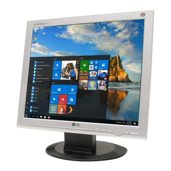
COLOR MONITOR
SERVICE MANUAL
CHASSIS NO. : CL-82
MODEL:
(
) **Same model for Service
CAUTION
BEFORE SERVICING THE UNIT,
READ THE SAFETY PRECAUTIONS IN THIS MANUAL.
-
+
Website:http://biz.LGservice.com
E-mail:http://www.LGEservice.com/techsup.html
L1717S
(L1717S-SNN.AN**EP)
L1717S
(L1717S-BNN.AN**EP)
L1717S
(L1717S-GNN.AN**EP)
*To apply the MSTAR Chip.
Advertisement
Table of Contents

Summarization of Contents
Monitor Specifications
LCD Panel Specifications
Details the physical and electrical properties of the LCD module, including size and type.
Monitor Optical Performance
Defines key visual performance metrics like viewing angle, luminance, and contrast ratio.
Video Signal Input
Describes the accepted video signal types, voltage levels, and impedance.
Maximum Display Resolution
Specifies the highest resolution supported by the monitor, including refresh rate.
Monitor Power Requirements
Outlines the power input specifications and consumption levels for different modes.
Operating Environment Specifications
Lists the recommended temperature, humidity, and expected lifespan.
Monitor Physical Dimensions and Weight
Provides the physical measurements and weight of the monitor with tilt/swivel.
Precautionary Measures
Safety Component Handling Precautions
Guidance on replacing safety-critical components to prevent hazards.
LCD Module Handling Safety
Instructions for safely handling the LCD module to prevent damage and ensure user safety.
Electric Shock Safety Warning
Critical warnings regarding high voltage and proper procedures to avoid electric shock.
Leakage Current Hot Check
Procedure for checking leakage current using a specific circuit setup.
Servicing Precautions
General Servicing Precautions
Broad safety guidelines for servicing, including power disconnection and ESD prevention.
ESD Device Handling
Methods to prevent damage to sensitive electronic components from static electricity.
Soldering and Component Replacement
Detailed procedures for soldering, IC, transistor, diode, and resistor replacement.
Circuit Board Trace Repair
Techniques for repairing damaged copper patterns on circuit boards using jumper wires.
Block Diagram Description
Video Controller Part Description
Explains the role of the video controller in signal amplification and digital conversion.
Power Supply System Description
Details the power conversion stages and voltage regulation within the monitor.
MICOM System Description
Describes the Microcomputer unit, EEPROM, and sync signal processing.
LIPS Board Block Diagram
LIPS Board Operation
Explains the functions of EMI components, rectifier, energy transfer, and control circuits.
Adjustment Procedures
Port Setup for Adjustment
Procedure for configuring the system port for monitor adjustment software.
EDID Data Management
Instructions for reading, writing, and editing Extended Display Identification Data.
Service OSD Menu
Service OSD Menu Options
Details the advanced service menu options for color, NVRAM, aging, and module settings.
Troubleshooting Guide
No Power Troubleshooting
Diagnostic steps for when the monitor does not power on, checking voltage and connections.
No Raster Troubleshooting (LIPS)
Steps to diagnose no display on LIPS models, checking power and CCFL lamp.
No Raster Troubleshooting (MSTAR)
Diagnostic flow for no display on MSTAR models, checking sync signals and components.
DPM Troubleshooting
Procedure for diagnosing issues related to the Digital Panel Management (DPM) function.
Schematic Diagrams
TSU56AL/TSU16AL Schematic
Detailed circuit diagram for the TSU56AL and TSU16AL ICs.
MICOM Schematic Diagram
Circuit diagram illustrating the Microcomputer and associated components.
Power Supply Schematic
Circuit diagram showing the power supply unit and its components.
Connector and Jacks Schematic
Diagram detailing monitor connectors, jacks, and their internal wiring.


Need help?
Do you have a question about the FLATRON L1717S-SN and is the answer not in the manual?
Questions and answers