Table of Contents
Advertisement
JVC SERVICE & ENGINEERING COMPANY OF AMERICA
DIVISION OF JVC AMERICAS CORP.
Head office
:
1700 Valley Road Wayne, New Jersey 07470-9976
:
10 New Maple Avenue Pine Brook, New Jersey 07058-9641
East Coast
:
705 Enterprise Street Aurora, Illinois 60504-8149
Midwest
:
5665 Corporate Avenue Cypress, California 90630-0024
West Coast
:
1500 Lakes Parkway Lawrenceville, Georgia 30043-5857
Atlanta
:
2969 Mapunapuna Place Honolulu, Hawaii 96819-2040
Hawaii
JVC CANADA INC.
Head office
:
21 Finchdene Square Scarborough, Ontario M1X 1A7
:
Montreal
16800 Rte Trans-Canadienne, Kirkland, Quebec H9H 5G7
:
Vancouver
13040 Worster Court Richmond, B.C. V6V 2B3
(973)317-5000
(973)396-1000
(630)851-7855
(714)229-8011
(770)339-2582
(808)833-5828
(416)293-1311
(514)871-1311
(604)270-1311
S40895-04
Printed in Japan
SERVICE MANUAL
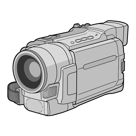
DIGITAL VIDEO CAMERA
GR-DVL220U,DVL320U,DVL520U,
DVL522U,DVL720U
SPECIFICATIONS
(The specifications shown pertain specifically to the model GR-DVL320/DVL520/DVL720)
Camcorder
General
Power supply
: DC 11.0 V } (Using AC Adapter)
DC 7.2 V } (Using battery pack)
Power consumption
LCD monitor off, viewfinder on : Approx. 4.3 W
LCD monitor on, viewfinder off : Approx. 5.3 W
Video light
: Approx. 3.5 W
Dimensions (W x H x D) : 79 mm x 89 mm x 167 mm (3-1/8" x 3-9/16" x 6-5/8")
(with the LCD monitor closed and the viewfinder
pushed down)
Weight
: Approx. 570 g (1.3 lbs) (GR-DVL720)
Approx. 560 g (1.3 lbs) (GR-DVL520)
Approx. 550 g (1.3 lbs) (GR-DVL320)
Operating temperature : 0°C to 40°C (32°F to 104°F)
Operating humidity
: 35% to 80%
Storage temperature
: –20°C to 50°C (–4°F to 122°F)
Pickup
: 1/4" CCD
Lens
: F 1.8, f = 3.8 mm to 38 mm, 10:1 power zoom lens
Filter diameter
: ø37 mm
LCD monitor
: 3.5" diagonally measured, LCD panel/TFT active
matrix system (GR-DVL720)
2.5" diagonally measured, LCD panel/TFT active
matrix system (GR-DVL520/DVL320)
Viewfinder
: Electronic viewfinder with 0.24" black/white LCD
Speaker
: Monaural
Digital Video Camera
Format
: DV format (SD mode)
Signal format
: NTSC standard
Recording/Playback format : Video: Digital component recording
: Audio: PCM digital recording, 32 kHz 4-channel (12-bit),
48 kHz 2-channel (16-bit)
Cassette
: Mini DV cassette
Tape speed
: SP: 18.8 mm/s
LP: 12.5 mm/s
Maximum recording time : SP: 80 min.
(using 80 min. cassette) LP: 120 min.
This service manual is printed on 100% recycled paper.
COPYRIGHT © 2001 VICTOR COMPANY OF JAPAN, LTD.
Digital Still Camera Function (GR-DVL720/DVL520 only)
Storage media
: SD Memory Card/MultiMediaCard
Compression system : JPEG (compatible)
File size
: 2 modes (1024 x 768 pixels, 640 x 480 pixels)
Picture quality
: 2 modes (FINE/STANDARD)
Approximate number of storable images
with memory card [8 MB] (provided)
FINE
: 20 (1024 x 768 pixels), 45 (640 x 480 pixels)
STANDARD
: 65 (1024 x 768 pixels), 160 (640 x 480 pixels)
For other memory cards, «g. 27.
Connectors
S-Video
Output
: Y:1 V (p-p), 75 , analog
C:0.29 V (p-p), 75 , analog
AV
Video output
: 1 V (p-p), 75 , analog
Audio output
: 300 mV (rms), 1 k, analog, stereo
DV
Output
: 4-pin, IEEE 1394 compliant
Input
: 4-pin, IEEE 1394 compliant
USB (GR-DVL720/DVL520 only) : 5-pin
PC (GR-DVL320 only)
:
ø2.5 mm, 3-pole
EDIT (GR-DVL720/DVL520 only) : ø3.5 mm, 2-pole
JLIP (GR-DVL320 only)
: ø3.5 mm, 4-pole
AC Adapter
Power requirement
U.S.A. and Canada : AC 120 V `, 60 Hz
Other countries
: AC 110 V to 240 V `, 50 Hz/60 Hz
Output
: DC 11 V } , 1 A
Specifications shown are for SP mode unless otherwise indicated. E & O.E.
Design and specifications subject to change without notice.
No. 86658
December 2001
Advertisement
Table of Contents

Related Manuals for JVC DVL520U


Summarization of Contents
Important Safety Precautions
Precautions During Servicing
Guidelines and warnings to ensure safety during product repair and maintenance procedures.
Safety Checks After Servicing
Insulation Resistance Test
Verifies specified insulation resistance between power cord prongs and exposed parts.
Dielectric Strength Test
Confirms specified dielectric strength between power cord prongs and exposed parts.
Clearance Distance Verification
Checks specified clearance distance between terminals and surrounding metallic parts.
Leakage Current Test Procedure
Measures leakage current between earth ground/power cord and exposed parts.
Grounding Checks for Class 1 Models
Confirms specified grounding impedance between earth pin and exposed parts.
Section 1 Disassembly Procedures
Before Assembly and Disassembly
Covers essential precautions, connector handling, and tool requirements before starting disassembly.
Jigs and Tools for Disassembly, Assembly, and Adjustment
Lists specialized tools and jigs required for performing disassembly, assembly, and adjustment procedures.
Disassembly/Assembly of Cabinet Parts and Board Assembly
Details the step-by-step procedures for dismantling and reassembling the camera's external parts and internal boards.
Monitor Assembly and Hinge Procedures
Instructions for the disassembly and assembly of the LCD monitor assembly and its hinge mechanism.
E. VF Assembly Disassembly and Assembly
Procedures for disassembling and reassembling the Electronic Viewfinder (E.VF) assembly for B/W viewfinders.
OP Block Assembly and CCD Board Assembly Procedures
Guides for disassembling and assembling the OP block and CCD board assemblies, including crucial precautions.
Emergency Display Codes and Troubleshooting
Explains emergency error codes displayed on the LCD or viewfinder and their possible causes.
Service Notes and Repair Information
Provides important notes and references for service technicians regarding disassembly and reassembly steps.
Section 2 Mechanism Adjustment
Preliminary Remarks on Adjustment and Repair
Covers essential precautions and notes for mechanism adjustment and repair procedures.
Jigs and Tools for Mechanism Adjustment
Lists specialized jigs and tools required for performing mechanism disassembly, assembly, and adjustment.
Mechanism Assembly and Mode Explanation
Details the mechanism assembly, its modes, and the general statement for procedures.
Mechanism Disassembly and Assembly Procedures
Provides detailed step-by-step procedures for disassembling and assembling the mechanism components.
Mechanism Phase Checkup and Adjustment
Guides for checking and adjusting the mechanism phase, ensuring correct part alignment.
Mechanism Adjustments and Assembly
Instructions for assembling the slide deck and main deck assemblies, including tension pole location.
Service Notes for Mechanism Parts
A chart to manage mechanism parts removed during disassembly and their corresponding quantities.
Jig Connector Cable Connection
Details the connection procedure for the jig connector cable for testing and adjustment.
Section 3 Electrical Adjustment
Electrical Adjustment Precautions
Covers essential precautions for electrical adjustments, including required test equipment.
Required Test Equipment for Adjustment
Lists all test equipment, tools, and software needed for performing electrical adjustments.
Electrical Adjustment Setup
Details the setup procedure for electrical adjustments using a personal computer and service support system.
Need help?
Do you have a question about the DVL520U and is the answer not in the manual?
Questions and answers