Advertisement
INTRODUCTION
- This manual is meant to provide customers with any information on the machine and its specifications and the necessary operating and maintenance instructions in order to guarantee the best possible use of the machine and preserve its efficiency in time.
- This manual is to be handed over to qualified personnel well informed about the use of the machine and its periodical maintenance.
INFORMATION ON THE MACHINE
GENERAL PRECAUTIONS
- The CUTTER should be operated only by qualified people who should be informed about the safety measures described in this manual.
- In case of personnel turn-over, training is to be provided in advance.
- Before starting cleaning and maintenance, disconnect the machine's plug from the power supply socket.
- Assess the residual risks carefully when protection devices are removed to carry out cleaning and maintenance.
- Cleaning and maintenance require great concentration.
- A regular control of the electric supply cords is absolutely necessary; a wornout or damaged cord can expose users to serious electric shock hazard.
- If the machine shows malfunctions, it is recommended not to use it and to abstain from trying to repair it; please call the "SERVICE CENTRE".
- Do not use the machine for products with bones, frozen foods, fishes or any product other than food.
- Do not introduce fingers in the opening or inside the machine when it is functioning.
- The manufacturer is not liable in the following cases:
- if the machine has been tampered by non-authorized personnel;
- if some parts have been substituted by non original spare parts;
- if the instructions contained in this manual are not followed accurately;
- if the machine surface is not cleaned with the right product.
SAFETY DEVICES INSTALLED ON THE MACHINE
mechanical safeties
The mechanical safety devices installed on the machine, described in this manual, comply with EC 89/392 and mod. EC 91/368, 92/31, 93/44, 93/68.
- The safety protections are (see 1.3.3) the cover, which can be removed only when the tank locking arm is up.
electrical safeties
The electrical safety devices installed on the machine, described in this manual, comply with EC 73/23, 89/336, mod. EC 91/368, 92/31, 93/44, 93/68 and regulations EC EN 60335-1, EN 55014. The machine is equipped with:
- micromechanic which stop the machine when the closing arm is lifted (see FIG. n°1), and does not permit to start the machine if the cover is not closed;
- relay which in case the power supply is missing; it is necessary to restart the machine.
Even though the professional CUTTER CE are provided with electrical and mechanical protections (when the machine is working and for maintenance and cleaning operations), there are still RESIDUAL RISKS (EEC 89/392 point 1.7.2) that cannot be eliminated completely, these risks are mentionned in this manual under WARNING. These risks are cutting dangers caused by the knives during the loading of the product, or during the maintenance operations.
MACHINE DESCRIPTION
general description
Our firm has designed and manufactured the professional CUTTER CE to cut, crumble, whip, knead foodstuffs as vegetables, meat, bread, etc and guarantee:
- the highest degree of safety in functioning, cleaning and maintenance;
- the highest hygienic standards due to an accurate choice of materials and a smooth design of the CUTTER components which come into contact with foodstuffs in order to obtain easy and total cleaning and easy disassembly;
- solidity and stability of all components;
- the lowest noise level thanks to belt drive;
- great handiness.
construction features
CUTTER models belonging to the above mentioned line are made of AISI 304 stainless steel. This guarantees high hygienic standards of those parts which come into contact with foodstuffs and offers resistance to acids, salts and oxidation processes.
The blades are made of AISI 420 stainless steel used for cutlery; they are grinded and hardened and can cut, mince, whip and knead without changing tools. The basin is made of stainless steel 18/10 and is provided with heat spreading bottom and handles guaranteeing great handiness and easy removal.
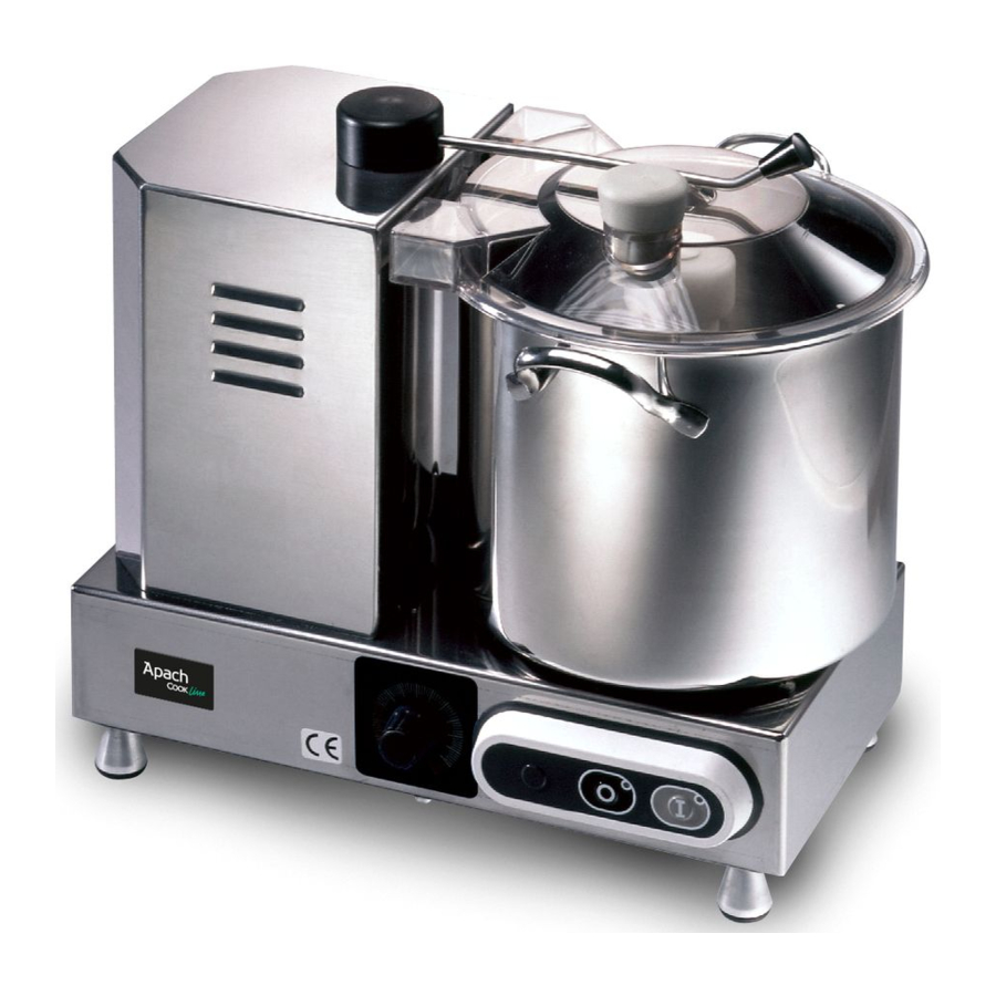
CUTTER components
FIG. n°1 - General view of the CUTTER


CUTTER with speed dial knob.
LEGEND:
- Basin
- Lid
- Closing arm
- Body
- Information plate - serial number
- Power supply cord
- Feet
- Push-button panel
- Speed dial knob (for mod. VV)
TECHNICAL DATA
OVERALL DIMENSIONS, WEIGHT, CHARACTERISTICS
FIG. n°2 - Overall dimensions drawings

TAB. n°1 - OVERALL DIMENSIONS AND TECHNICAL FEATURES
| Models | U.m. | C4 | C4 VV | C6 | C6 VV | C9 VV |
| Length A | mm | 380 | 380 | 380 | 380 | 470 |
| Width B | mm | 320 | 320 | 320 | 320 | 330 |
| Height C | mm | 370 | 370 | 370 | 370 | 395 |
| Max. height C | mm | 270 | 270 | 320 | 320 | 400 |
| Bowl capacity | l | 3.3 | 3.3 | 5.3 | 5.3 | 9.4 |
| Bowl filling level | l | 1.5 | 1.5 | 3.1 | 3.1 | 5.4 |
| Blade rotations | g/1' | 2600 | 1100÷2600 | 2600 | 1100÷2600 | 1100÷2600 |
| Motor | HP/W | 0.5 / 350 | 0.5 / 350 | 0.5 / 350 | 0.5 / 350 | 0.5 + 0.5 / 700 |
| Power source | Mn | 230 V / 50 Hz | ||||
| Net weight | Kg | 10 | 10 | 11 | 11 | 25 |
| Degree of noise | dB | ≤ 75 | ≤ 75 | ≤ 75 | ||

Electrical features of the CUTTER are shown in the information plate placed on the back side of the machine; before connecting the CUTTER to the electric system see Electric connections.
MACHINE RECEIPT
MACHINE SHIPMENT
(see FIG. n°3)
The CUTTER is accurately packed and then shipped from our warehouses; the package includes:
FIG. n°3 - Package description

- a strong cardboard box;
- the machine;
- this manual;
- whetstone;
- scraper;
- EC conformity declaration.
PACKAGE CHECK UP ON RECEIPT
If no external damage is evident on the package upon its arrival, open it and check that all the components are inside (see FIG. n°3). If the package has suffered rough handling, bumps or crashes, the carrier must be informed about any damage; moreover a detailed report on the extent of the damage caused to the machine must be filled within three days from the delivery date shown in the shipping documents. Do not overturn the package!! When the package is transported, make sure the box is lifted by the 4 corners (parallel to the ground).
INSTALLATION
SETTING UP OF THE MACHINE
The machine must be installed on a working table suitable for its overall dimensions shown in Tab. 1 (in accordance with the model), therefore it must be adequately large, well levelled, dry, smooth, resistant, stable.
Moreover the machine must be installed in a room with max. 75% not saline humidity at a temperature between +5°C and +35°C; that is to say in a place that does not provoke the machine failure.
ELECTRICAL CONNECTIONS
Tha appliance is equipped with a power supply cord which section 3x1.5mm², length 1.5m with a "SUKO" plug.
Connect the appliance to 230 Volt 50 Hz, by interposing a differentialmagnetothermic switch of 10A, ∆ I = 0.03A. Check that the earthing is fully operational. Moreover check that the features on the rating plate - serial number (see FIG. n°4) correspond to the features shown in the consignment and delivery note.
FIG. n°4 - Rating plate - serial number

ELECTRIC DIAGRAMS
Single-phase electric diagram
FIG. n°5 - Single-phase electric diagram.

Single-phase electric diagram. CUTTER with speed dial knob.
FIG. n°6 - Single-phase electric diagram. CUTTER with speed dial knob.

OPERATION CHECKS
Check the proper functioning of the machine according as follows:
- press the start button "I" and the stop button "0";
- check whether the machine stops after the lid has been removed;
- in case of a CUTTER equipped with a speed dial knob, check whether the number of rotations increases by adjusting the knob clockwise.
USE OF THE MACHINE
CONTROLS
Controls are placed on the CUTTER body as shown in the picture below.
NOTE: The speed dial knob (1) is installed only in the vv model.
FIG. n°7 - Position of controls

- Dial knob to set the number of rotations;
- Start button "I".
- Stop button "0".
LOADING OF THE PRODUCT
(see FIG. n°8)
NOTE: Products to be cut must be loaded onto the basin when the motor is switched off and in case of a CUTTER vv after the speed dial knob has been set to the "0" position.
The procedure is as follows:
- rotate the arm (ref.1 - FIG. n°8) anticlockwise in order to remove the lid (ref. 2 - FIG. n°8);
![]()
load the product into the basin (ref. 3 - FIG. n°8) and be careful of the two blades; if the product is in large pieces, break them into smaller pieces by hand before putting them onto the basin.
![]()
Fill with liquid products to the maximum height shown on the bowl;- to avoid accidents, place yourself correctly (seeFIG. n°9): the body must be perpendicular to the working table; the hands must not force on the machine or stop its movement.
Never lean on the machine and avoid any direct contact with it.
FIG. n°9 - Correct position

- re-position the lid and rotate the arm to closed position;
- start the machine by pushing the start button "I" (ref. 2 - FIG. n°7);
- don't use la machine at low speed for long time;
- load additional quantities of product through the upper hole (ref. 4 - FIG. n°8) during cutting, if necessary;
FIG. n°8 - Loading of the product.
![]()
- once the product has been cut, stop the machine by pushing the red stop button (ref. 3 - FIG. n°7). If the CUTTER is provided with a speed dial knob, adjust it to the "0" position (ref. 3 - FIG. n°7) and then stop the machine.


SHARPENING OF ROTATING BLADES

Follow the the instructions below to sharpen the two blades if they do not cut properly:
- rotate the closing arm (1) so as to remove the lid (2);
- remove the rotating blade holder (3);
- use the sharpening stone supplied with the machine and sharp knife on the cutting edge, from internal towands esternal till reviving the blade edge.
FIG. n°10 - Knives holder removal

ORDINARY CLEANING
GENERAL FEATURES
- The CUTTER cleaning must be carried out at least once a day or more frequently, if necessary.
- Cleaning must be extremely accurate for those parts of the CUTTER which come into direct or indirect contact with foodstuffs.
- The CUTTER must not be cleaned with water-cleaners and high pressure jets of water. Tools, brushes and other devices likely to damage the CUTTER's surface must not be used.
Before carrying out any cleaning operation it is necessary:
- to disconnect the power supply plug from the socket to isolate the CUTTER from the rest of the electric circuit completely;
- to set the dial knob to the "0" position in case of a vv model.
CLEANING PROCEDURE OF THE MACHINE
(see FIG. n°10)
cleaning of lid, rotating blade holder and basin
Rotate the closing arm (1) and lift the lid (2).
Now the blade holder (3) and the basin (4) can be easily removed by pulling them upwards (a).
Once they have been removed, clean them with water and neutral detergent.
NOTE: proceed with this operation wearing protection gloves.
ordinary cleaning
NOTE: Disconnect the power supply plug
Cleaning of the machine body on the worktable can be carried out with neutral detergent and a damp cloth frequently rinsed in water.
When cleaning has been completed, dry the components accurately.
MAINTENANCE
GENERAL FEATURES
Before starting any maintenance activity it is necessary:
- to disconnect the power supply plug from the socket to isolate the CUTTER from the electric circuit completely.
- if the CUTTER is a vv model, to set the speed dial knob to the "0" position.
BELT
The belt does not need to be adjusted. Generally it must be replaced after 3/4 years; in this case, please call the "SERVICE CENTRE".
FEET
Feet might deteriorate and lose elasticity; consequently the stability of the machine might be reduced. In this case they must be replaced.
POWER SUPPLY CORD
Periodically check whether the power supply cord is worn-out and, if this is the case, please call the "SERVICE CENTRE" to have it replaced.
BLADES
Check that blades have not lose more than 5 mm of thickness after sharpening. Call the "SERVICE CENTRE" to have them replaced.
KEYBOARD LABEL
The label of the keyboard could be marked and/or holed. In this case, please call the "SERVICE CENTRE" to have it replaced.
Documents / ResourcesDownload manual
Here you can download full pdf version of manual, it may contain additional safety instructions, warranty information, FCC rules, etc.
Advertisement


Need help?
Do you have a question about the C4 and is the answer not in the manual?
Questions and answers