Table of Contents
Advertisement
Quick Links
OPTIONAL ACCESSORIES
Model Number
Description
BAYBASE205
Downflow subbase for downflow models
only
BAYFLTR200
External side filter rack
BAYFLTR203
Filter kit horizontal for 17.5" cabinet
BAYFLTR204
Filter kit horizontal for 21" cabinet
BAYFLTR205
Filter kit horizontal for 24.5" cabinet
BAYFLTR317
Cleanable filter for 17.5" cabinet upflow
only
BAYFLTR321
Cleanable filter for 21" cabinet upflow
only
BAYFLTR324
Cleanable filter for 24.5" cabinet upflow
only
BAYLPKT210B
Propane conversion kit
BAYLPSS210B
LP kit with stainless steel burners
BAYRACK960A
Internals filter rack kit for upflow models
BAYVENT800B
Masonry chimney vent kit for upflow only
KIT09224
Filter clip kit
BAYBRCKFLT10
Downflow bracket kit
FLR01185
Filter for 14-1/2" cabinet downflow only
FLR01186
Filter for 17-1/2", 21", 24-1/2" cabinet
downflow only
INSTALLER'S GUIDE
Upflow/Horizontal — Downflow/Horizontal, Gas-Fired Furnaces,
"Fan Assisted Combustion System"
M801P040AU24AA
M801P100CU48AA
M801P060AU24AA
M801P100CU60AA
M801P060AU36AA
M801P120DU60AA
M801P080BU48AA
M801P140DU60AA
M801P100BU36AA
ALL phases of this installation must comply with
NATIONAL, STATE AND LOCAL CODES
IMPORTANT — This Document is customer property and is to
remain with this unit. Please return to service
information pack upon completion of work.
For VENT SIZING INFORMATION see:
USA —
National Fuel Gas Code
CANADA—
Natural Gas Installation Code
Propane Installation Code CAN/ CGA-B149.2 (latest version)
M801P040AD24AA
M801P060AD24AA
M801P060AD36AA
M801P080BD45AA
ANSI Z223.1/ NFPA 54 (latest version)
CAN/ CGA-B149.1 (latest version)
Upflow/ Horizontal*
*Horizontal Conversion for these furnaces may be left
or right side rotation.
18-CD34D1-1
M801P100CD48AA
M801P100CD60AA
M801P120DD60AA
M801P140DD60AA
Downflow/ Horizontal*
A341789P12
Advertisement
Table of Contents

Related Manuals for Ingersoll-Rand M801P040AD24AA


Summary of Contents for Ingersoll-Rand M801P040AD24AA
- Page 1 18-CD34D1-1 INSTALLER’S GUIDE Upflow/Horizontal — Downflow/Horizontal, Gas-Fired Furnaces, “Fan Assisted Combustion System” M801P040AU24AA M801P100CU48AA M801P040AD24AA M801P100CD48AA M801P060AU24AA M801P100CU60AA M801P060AD24AA M801P100CD60AA M801P060AU36AA M801P120DU60AA M801P060AD36AA M801P120DD60AA M801P080BU48AA M801P140DU60AA M801P080BD45AA M801P140DD60AA M801P100BU36AA ALL phases of this installation must comply with NATIONAL, STATE AND LOCAL CODES IMPORTANT —...
-
Page 2: Safety Section
INSTALLER’S GUIDE SAFETY SECTION 10. This product must be gas piped by a Licensed Plumber or Gas Fitter in the Commonwealth of Massachusetts. The following safety practices and precautions must be followed during the installation, servicing, and operation of this furnace. Safety signal words are used to designate a degree or level of seriousness associated with a particular hazard. -
Page 3: Table Of Contents
INSTALLER’S GUIDE Contents Safety Section ..............2 General Installation Instructions ........2 Location and Clearances ..........4 Outline Drawings .............. 5 Upflow Installation ............7 Downflow Installation ............7 WARNING Horizontal Installation ............7 CARBON MONOXIDE POISONING HAZARD Air for Combustion and Ventilation ........8 Failure to follow the steps outlined below for Duct Connections ............ -
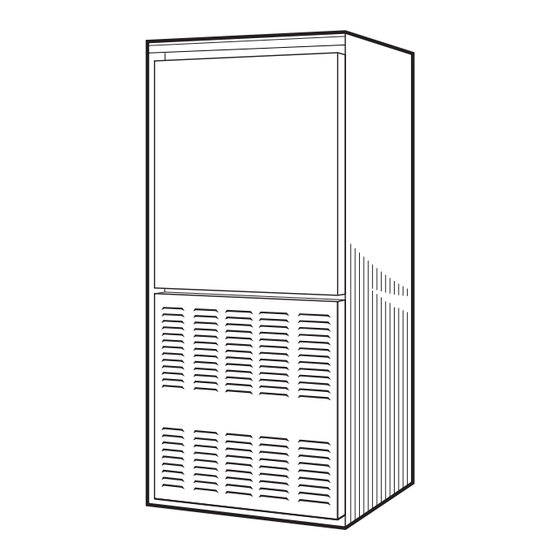
Page 4: Outline Drawings
INSTALLER’S GUIDE into place, be sure to consider the following requirements: CAUTION Is the location selected as near the chimney or vent and as To prevent shortening its service life, the furnace centralized for heat distribution as practical? should not be used as a “Construction Heater” Do all clearances between the furnace and enclosure during the finishing phases of construction equal or exceed the minimums stated in Clearance Table... - Page 5 INSTALLER’S GUIDE 18-CD34D1-1...
- Page 6 INSTALLER’S GUIDE 18-CD34D1-1...
-
Page 7: Upflow Installation
INSTALLER’S GUIDE UPFLOW INSTALLATION Required floor opening: (DOWNFLOW) Figure 3 and Table 1 The coil is always placed downstream of the furnace airflow. Apply gasket material (duct seal field supplied) to ALL mating surfaces between the furnace and the coil case. A (width) B (depth) FURNACE... -
Page 8: Air For Combustion And Ventilation
INSTALLER’S GUIDE If the furnace is suspended using perforated steel strap (plumber’s AIR FOR COMBUSTION AND strap), it must be supported at all four corners and in the middle VENTILATION at the front of the furnace. The forward most screw on the side Adequate flow of combustion and ventilating air must not be of the furnace may be used to connect the strapping (See Figure obstructed from reaching the furnace. - Page 9 INSTALLER’S GUIDE TABLE 2 MINIMUM AREA IN SQUARE FEET FOR UNCONFINED SPACE INSTALLATIONS FURNACE MAXIMUM WITH 8 FOOT CEILING BTUH / INPUT RAT- MINIMUM AREA IN SQUARE FEET OF UNCONFINED SPACE 40,000 60,000 80,000 100,000 120,000 140,000 TABLE 3 MINIMUM FREE AREA IN SQUARE INCHES EACH OPENING (FURNACE ONLY) Furnace Air From Outside...
-
Page 10: Duct Connections
INSTALLER’S GUIDE DUCT CONNECTIONS Return Air Duct Connection All return air duct systems should provide for installation of Air duct systems should be installed in accordance with standards return air filters. for air conditioning systems, National Fire Protection Association Pamphlet No. 90. They should be sized in accordance with ACCA NOTE: For Upflow 5 ton airflow models, if the airflow Manual D or whichever is applicable. -
Page 11: Return Air Filter
(filter directly beneath bottom 24-1/2" 1 - 24 X 20 X 1 M801P140DU60AA side return) not recommended due to noise considerations. If used, securely M801P040AD24AA BAYBRCKFLT10 attach 1/2" mesh metal hardware cloth M801P060AD24AA 14-1/2" 2 - FLR01185 protective screen to the inside bottom of M801P060AD36AA filter grill. -
Page 12: General Venting Instructions
INSTALLER’S GUIDE TABLE 5 CABINET FILTER FILTER BRACKET BAYBRCKFLT10 WIDTH SIZE LOCATION * 14-1/2" 2 - 14X20X1 12-7/8" 17-1/2" 2 - 16X20X1 14-3/8" 21" 2 - 16X20X1 13-1/8" 24-1/2" 2 - 16X20X1 11-5/8" * Location dimension is from end of duct to the screw holes for the bracket. -
Page 13: Venting Into A Masonry Chimney
INSTALLER’S GUIDE VENTING INTO A MASONRY CHIMNEY WARNING If the chimney is oversized, the liner is inadequate, or flue- CARBON MONOXIDE POISONING HAZARD gas condensation is a problem in your area, consider using the Failure to follow the steps outlined below for chimney as a pathway or chase for type “B”... - Page 14 INSTALLER’S GUIDE Venting of fan assisted appliances into external chimneys (one Maximum Vent or Tile π(D*) or more walls exposed to outdoor temperatures), requires the Lined Chimney Flow Area chimney be lined with type “B”, double wall vent or suitable flexible chimney liner material.
-
Page 15: Field Wiring Diagrams
INSTALLER’S GUIDE FIELD WIRING DIAGRAMS FIELD WIRING DIAGRAM FOR 1 STAGE FURNACE 1 STAGE HEATING USING A 1 STAGE HEATING THERMOSTAT NO COOLING FURNACE NOTE 6 NOTE 5 TO 115 V 1 PH., 60 HZ., POWER SUPPLY PER LOCAL CODES From drawing B342026 Rv 0 FIELD WIRING DIAGRAM FOR 1 STAGE FURNACE 1 STAGE HEATING, 1 STAGE COOLING... -
Page 16: Electrical Connections
INSTALLER’S GUIDE ELECTRICAL CONNECTIONS WARNING WARNING TO PREVENT AN EXPLOSION OR POSSIBLE INJURY, DEATH AND EQUIPMENT DAMAGE, The cabinet must have an uninterrupted or DO NOT STORE COMBUSTIBLE MATERIALS, unbroken ground according to National Electrical GASOLINE OR OTHER FLAMMABLE VAPORS OR Code, ANSI/NFPA 70 - “latest edition”... -
Page 17: Gas Piping
INSTALLER’S GUIDE GAS PIPING that the pressure switch contacts are open and the limit switch(es) contacts are closed, the draft blower will be energized. WARNING As the induced draft blower comes up to speed, the pressure switch contacts will close and the ignitor warm up period will FIRE - EXPLOSION HAZARD begin. - Page 18 INSTALLER’S GUIDE Use the following factors if necessary: CAUTION For 1 Cu. Ft. Dial Gas Flow CFH = Chart Flow Reading ÷ 2 For 1/2 Cu Ft. Dial Gas Flow CFH = Chart Flow Reading ÷ 4 Replace and/ or tighten all plugs removed or For 5 Cu.
-
Page 19: High Altitude Derate
INSTALLER’S GUIDE TABLE 12 Regulator Outlet Pressure Boss Adjust- GAS FLOW IN CUBIC FEET PER HOUR 2 CUBIC FOOT DIAL ment SEC. FLOW SEC. FLOW SEC. FLOW SEC. FLOW Inlet Pressure Boss (opt.) On/Off Switch White-Rodgers 36J gas valve Table 14 FINAL MANIFOLD PRESSURE SET- TINGS (inches w.c.) FUEL... -
Page 20: Lighting Instructions
INSTALLER’S GUIDE LIGHTING INSTRUCTIONS WARNING Lighting instructions appear on each unit. Each installation Disconnect power to the unit before removing the must be checked out at the time of initial start up to insure blower door. Failure to follow this warning could proper operation of all components. -
Page 21: Integrated Furnace Control Error Flash Codes
INSTALLER’S GUIDE ignition sequence up to two times after the sensor cools. If The following warning complies with State of California law, Proposition 65. ignition is not achieved, it will lockout the furnace. WARNING POWER FAILURE This product contains fiberglass wool insulation! If there is a power failure during a heating cycle, the system will restart the ignition sequence automatically when power Fiberglass dust and ceramic fibers are believed by... -
Page 22: Periodic Servicing Requirements
INSTALLER’S GUIDE WARNING DISCONNECT POWER BEFORE SERVICING PERIODIC SERVICING REQUIREMENTS GENERAL INSPECTION — Examine the furnace NOTE: Be careful not to break igniter when removing installation annually for the following items: burners. a. All flue product carrying areas external to the furnace Clean burners with brush and/or vacuum cleaner. -
Page 23: Airflow Tables
INSTALLER’S GUIDE AIRFLOW TABLES FURNACE AIRFLOW (CFM) VS. EXTERNAL STATIC PRESSURE (IN. W.C.) MODEL SPEED TAP 0.10 0.20 0.30 0.40 0.50 0.60 0.70 0.80 0.90 4-HIGH - Black 1018 1004 3-MED - HIGH - Blue M801P040AU24AA 2-MED - LOW - Yellow 1-LOW - Red 4-HIGH - Black 1018... - Page 24 0.40 0.50 0.60 0.70 0.80 0.90 4-HIGH - Black 1070 1033 1000 3-MED - HIGH - Blue M801P040AD24AA 2-MED - LOW - Yellow 1-LOW - Red 4-HIGH - Black 1200 1155 1111 1056 1001 3-MED - HIGH - Blue 1025...
Need help?
Do you have a question about the M801P040AD24AA and is the answer not in the manual?
Questions and answers