Advertisement
Quick Links
EME-A22A
Please thoroughly read this instruction sheet before installing option cards and putting them into use.
The content of this instruction sheet may be revised without prior notice. Please consult our distributors or download the
most updated version at http://www.delta.com.tw/industrialautomation/.
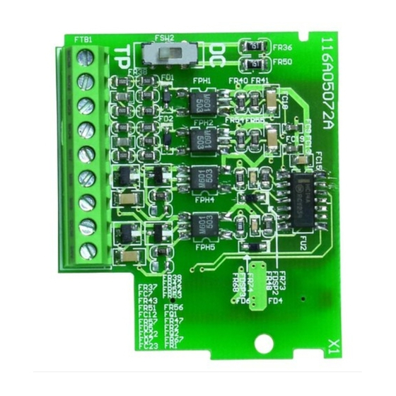
Layout
I/O Card (EME-A22A)
Installation
Make sure that the AC Motor Drive is powered off before
operation. DO NOT insert or remove the card when the AC
Motor Drive is powered on.
Please mount the extension card as shown and fix it with
the screw packed with the card.
Terminals Screw Torque: Maximum 5kgf-cm
Wire Gauge: 14 ~ 24 AWG (2.1 ~ 0.2 mm
NOTE
Only when the extension card is correctly installed on
the AC Motor Drive, the extension card will be
automatically detected. The parameters can be set in
Group 12. If extension card is not installed, only
parameters Group 0 ~ Group 10 can be set. Refer to
Chapter 5: Parameters in the user manual for further
details.
Specification
Environmental
o
Operating
-10
C to 50
Temperature
frozen)
Storage
o
-20
C to + 60
Temperature
Ambient
Less than 90%RH (non-condensing)
Humidity
Installation
Below 1000m
Altitude
Below 20 Hz: Maximum 9.81 m/s
Vibration
20 ~ 50Hz: Maximum 5.88 m/s
Analog Extension Card for VFD-E Series Instruction Sheet
Screw torque:
Maximum 2kgf-cm
2
)
o
C (non-condensing and not
o
C
2
(1G)
2
(0.6G)
NOTE
Always use this product in a clean indoor location free
from dust, corrosive gas and liquid.
Inputs/Outputs
EME-D33A
Terminal
Symbols
Input Voltage: 0 ~ 10VDC =0 ~ Maximum
Output Frequency (Pr.01.00)
Input Impedance: 100KΩ
Resolution: 12 bits
AI1
Input Current: DC 0 ~ 20mA=0 ~ Maximum
AI2
Output Frequency (Pr.01.00)
Input Impedance: 250Ω
Resolution: 12 bits
Voltage/Current Switch: Please refer to the
following diagram
Output Voltage: DC 0 ~ 10V
Output Impedance: 1K ~ 2MΩ
Resolution: 12 bits
AO1
Output Current: DC 0 ~ 20mA
AO2
Output Impedance: 0 ~ 500Ω
Resolution: 12 bits
Voltage/Current Switch: Please refer to the
following diagram
ACM
Analog control signal common
Voltage/Current Switch
AVI3
AVI4
AVO1
ACI2
ACI3
ACO1
Notes
When the relays are used to switch inductive loads (relays,
contactors, motors, etc), connect an RC network or Varistor
parallel to the load to suppress voltage spikes.
For safety, it is recommended to use fuses for the circuitry
that is switched by the relays. The fuse specification must
be within the specified contact limits.
Please use shielded wires to avoid interferences and
connect the shield to ground.
The ends of wires must be tinned or crimped.
To avoid interference, route the extension card wires
separately and as far away (at least 15cm) as possible from
other control wires, motor wires and power wires, etc.
Where these wires must cross each other, please make
o
sure they are at a 90
angle.
Always use and operate this product within the limit of its
specifications.
2007-07-09
5011659501-AAT1
Descriptions
AVO2
ACO2
Advertisement

Related Manuals for Delta Electronics EME-A22A


Summary of Contents for Delta Electronics EME-A22A
- Page 1 The content of this instruction sheet may be revised without prior notice. Please consult our distributors or download the most updated version at http://www.delta.com.tw/industrialautomation/. Layout I/O Card (EME-A22A) Installation Make sure that the AC Motor Drive is powered off before operation.
- Page 2 EME-A22A 請詳細閱讀下列說明後才使用本產品,以確保使用安全。 由於產品精益求精,當內容規格有所修正時,請洽詢代理商或至台達網站(http://www.delta.com.tw/industrialautomation/) 下載最新版本。 外觀 類比輸入/輸出卡 (EME-A22A) 安裝方式 安裝前請確認驅動器在斷電狀態下。 請以下圖方式安裝擴充卡並使用包裝內的螺絲固定以避免擴 充卡鬆脫。 端子螺絲扭力︰Maximum 5kgf-cm 線徑︰14 ~ 24 AWG (2.1 ~ 0.2 mm NOTE 若擴充卡正確安裝至變頻器上,變頻器將會自動偵測擴充卡且 可使用參數群 12 (Group 12)設定。如沒有安裝擴充卡的話, 參數只有 Group 0 ~ Group 10 可設定。詳細參數設定請參考 使用手冊第五章參數說明。 規格 環境 C to 50 C(無結露且無結凍)...
Need help?
Do you have a question about the EME-A22A and is the answer not in the manual?
Questions and answers