Delta Electronics TP05 Instruction Sheet
Delta program copy card instruction sheet
Hide thumbs
Also See for TP05:
- Connection manual (137 pages) ,
- Brochure (14 pages) ,
- User manual (330 pages)
Advertisement
Quick Links
Warning
Please read this instruction carefully before use.
S witch off the power before wiring.
T he display panel of TP05G and TP08G is waterproof. But please prevent grease, corrosive liquids and sharp
objects from contacting the TP05G and TP08G.
T he TP05G and TP08G require 24VDC input power. DO NOT connect input AC power supply to any of the RS-485
communication port; otherwise serious damage may occur. Check all the wiring again before switching on the
power.
D O NOT touch any terminal when the power is switched on. DO NOT touch any internal circuit in 1 minute after the
power is switched off.
M ake sure the ground terminal is correctly grounded in order to prevent electromagnetic interference.
P lease use the fixed support accessory which is packed together with the product provided by Delta. DO NOT
tighten the screws out of the normal torque specifications; otherwise serious damage may occur.
Introduction
Explanation & Peripherals
Thank you for choosing Delta TP Series. TP05G (BS2/BT2) has the features of high resolution 160×80 dots.
When the font is Traditional Chinese character and the font size is 8, TP05G (BS2/BT2) is able to display 14×7
Chinese character; TP08G (BS2/BT2) has the features of high resolution 240×128 dots. When the font is
Traditional Chinese character and the font size is 8, TP08G (BS2/BT2) is able to display 21×11 Chinese
character. Both of them provide multilingual display and two built-in communication ports, one is for RS-232 and
the other is for RS-485/RS-422. RS-232 and RS-485 can be used simultaneously. Besides, they also support
built-in RTC, communication/alarm indication LED, etc. functions. Besides, the users can purchase program
copy card (optional) to copy settings and programs quickly and save download time. Regarding the editing
software, there are various objects and images for various users' requirements. Please ensure to use TP series
with Delta power supply module, DVPPS01 and DVPPS02.
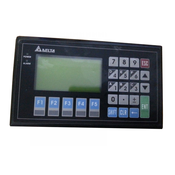
Product Outline
Power LED Indicator
Escape/Exi t Key
Al ar m LED Indicat or
Ar row Keys
Di splay Area
Numeric Keys
Enter Key
Function Keys
Multi pl e Function Keys
Function Specifications
Model
TP05G (BS2/BT2)
TP08G (BS2/BT2)
Specifications
Screen Type / Display
STN-LCD / Monochromatic
Color
Case Color
BS2: White color, BT2: Black color
The back-light automatic turn off time is 1~99 minutes (0 = do not turn off)
Backlight
(The back-light life is about 50 thousand hours at 25° C)
Resolution
160×80 dots
240×128 dots
83mm(W)× 41mm(H);
78mm(W)× 41mm(H);
Display Range
3.8" (diagonal preferred)
3.8" (diagonal preferred)
Contrast Adjustment
10 levels of adjustment
ASCII: (Code page 850) Alphanumeric (including European characters)
Language/Font
Taiwan: (Big 5 codes) Traditional Chinese Fonts
China: (GB2324-80 codes) Simplified Chinese Fonts
5 × 8 dots
32 characters × 10 rows
48 characters × 16 rows
8 × 8 dots
20 characters × 10 rows
30 characters × 16 rows
Display Text
8 × 12 dots
20 characters × 6 rows
30 characters × 10 rows
8 × 16 dots
20 characters × 5 rows
30 characters × 8 rows
Model
TP05G (BS2/BT2)
Specifications
Font Size
ASCII: 5×8, 8×8, 8×12, 8×16
1. Power on indication (Blink for three times)
Alarm LED Indicator (RED)
2. Communication error alarm
3. Special indication by user programming
Program Memory
1024KB flash memory
Unsynchronized transmission method: RS-232
Serial Communication Port
Data length: 7 or 8 bits, Stop bits: 1 or 2 bits
RS-232(COM1)
Parity: None/Odd/Even, Transmission speed: 9,600bps~115,200bps
RS-232: 9 PIN D-SUB male
Extension Communication
Unsynchronized transmission method: RS-485 / RS-422
Port
Data length: 7 or 8 bits, Stop bits: 1 or 2 bits
RS-422(COM1)
Parity: None/Odd/Even, Transmission speed: 9,600bps~115,200bps
RS-485(COM2)
RS-422: 9 PIN D-SUB male, RS-485: 6-Pin removal terminal
Battery Cover
DC 3V battery for HMI
1. Update firmware version
Extension Interface
2. The slot for program copy card
6-Pin Removal Terminal
Include DC 24V input and RS-485 communication input
Electrical Specifications
Model
TP05G (BS2/BT2)
Specifications
Display
Monochromatic STN LCD
83mm(W)× 41mm(H); 3.8" (diagonal
Effective Display Area
preferred)
5×8 dots 32 characters × 10 rows
8×8 dots 20 characters × 10 rows
Display Resolution
160×80
240×128
8×12 dots 20 characters × 6 rows
8×16 dots 10 characters × 5 rows
LCD Contrast Adjustment
Set by Software, adjust the contrast by the press button in the function table
LCD Backlight Type
LED Backlight: Automatic Turn-off Setting
Function / Numeric Keys
0~9,F1~F5, ESC, ± , CLR, ←,
‧
, SHIFT, ENTER and Arrow Keys (UP, DOWN )
External Input Power
24V (1.8W Max.)
Memory Capacity
1024K Byte
CPU
ST STR710RZT6
RAM of System
64K Byte
Communication Interface
COM1: RS-232/RS-422 COM2: RS-485
Waterproof Class of Front
IP66 / NEMA4 / UL Type4 indoor
Panel
Operating Temperature
0~50° C; 20-90% RH (non-condensing)
for Hardware
Storage Temperature for
-20~60° C
Hardware
5Hz
≦
f
<
9 Hz = Continuous: 1.75mm / Occasional: 3.5mm
Vibration
9Hz
≦
f
≦
1 50Hz = Continuous: 0.5g / Occasional: 1.0g
15g peak, 11ms duration, half-sine, three shocks in each direction per axis,
Shock
on 3 mutually perpendicular axes (total of 18 shocks)
Radiated Emission
CISPR11, Class A
Electrostatic Discharge
EN61000-4-2
Immunity
Radiated Immunity
EN61000-4-3
Electrical Fast Transient
EN61000-4-4
Weight / Dimensions
0.43kg; 210×122×45mm (Width(W) × Height(H) × Deep(D))
Cooling Method
Natural Air Cooling
Dimension and Installation
ENGLISH
Product Outlook and Dimensions (Units: mm, [ ]: inch)
Back Panel
Front Panel and Right Side Diagram
6-Pin Terminals:
Wire Gauge:12-24 AWG / Torque:4.5 lb.-inch
Mounting Dimensions (Panel Cutout)
Vertical View
Installation
Please insert TP05G/TP08G to the opening hole of panel and tighten the screws. However, if a firm mounting
TP05G/TP08G to the panel is needed, please use the mounting fixed support accessory which is packed
together with TP05G/TP08G, then insert the fixed support in the back and tighten the screws. Please refer to
the following sections for correct installation. (
If the fixed support is not installed well, Delta will not
guarantee the waterproof function. The screw torque should be 4-5(kg-cm). DO NOT exceed this specification
when tightening the screws; otherwise TP05G/TP08G may be damaged.)
Do not install and mount TP05G/TP08G in the following environment.
A location subjected to Airborne dust, metallic particles, oil and smoke, corrosive or flammable
gases and liquids.
A location where temperature and humidity will exceed specifications.
A location where vibration and shock will exceed specifications.
The flat surface should be a UL Type 4
Indoor Use Only
enclosure or equivalent (IP66/NEMA4). Please
refer to the figures below.
Installation Method of Insert Module
Password Function
TP08G (BS2/BT2)
If the users forgot the password, the password can be cleared by using the following code: 8888. This
universal code will clear the password and all TP05G/TP08G internal programs. The TP05G/TP08G will be
reset to the factory settings. Please pay close attention when using it. The password can be the alphabet from
A to Z or the number from 0 to 9. But it must use the function keys F0~F5 to input the password characters.
Please refer to the following table.
Function Key
Use Method
Numeric Key
0 ~ 9
This key is left direction key and it can
F1
be used to select the position of the
value.
Scrolls in a loop as follows
F2
A→B→C→D→E→F→G→H→I
Hardware Operation
When the users want to startup TP05G/TP08G, a 24VDC power is needed. After applying 24VDC power to
TP05G/TP08G, it will enter into the startup display and then enter the user-designed program. Pressing Esc
key and holding on for 5 seconds can return to system menu. There are five selections in the system menu
and are described below.
TP08G (BS2/BT2)
SELECTIONS
Use the connection cable (DVPACAB530) to connect the TP05G/TP08G serial communication
Download
port RS-232 to a PC. Then use the TPEditor software to download an application program to
Program
78mm(W)× 41mm(H); 3.8" (diagonal
TP05G/TP08G.
preferred)
Use the connection cable (DVPACAB530) to connect the TP05G/TP08G serial communication
5×8 dots 48 characters × 16 rows
Upload Program
port RS-232 to a PC. Then use the TPEditor software to upload an application program from
8×8 dots 30 characters × 16 rows
TP05G/TP08G.
Transfer a program between two TP05G/TP08G units.
8×12 dots 30 characters × 10 rows
1: Transmit Program ; 2: Receive Program
8×16 dots 30 characters × 10 rows
Copy Program
When transmit programs and data between two TP05G/TP08G units. Set one TP05G/TP08G to
"Receive Program" mode and the other TP05G/TP08G to "Transmit Program" mode. Please use
twisted pair wires to connect the two units via the RS-485 ports.
There are 8 items that used to modify TP05G/TP08G system settings:
1. Communication protocol: Setting the address of TP05G/TP08G, and the communication
string for either RS-232 or RS-485.
2. Contrast: Adjust the contrast of LCM display screen.
3. Back-light: adjust the automatic turn off time of LCM. Setting range is 00~99 seconds. If set
to 00, the LCM Back-light will not turn off.
4. Date and Time: It is used to set the TP05G/TP08G built-in RTC including year, month, day,
TP05G/TP08G
hour, minute, second and week. Also the internal battery capacity display is shown here.
Settings
5. Buzzer: Used to set the buzzer sound, normal mode or quiet mode.
6. Language Setting: Used to set the displayed language. English, Traditional Chinese,
Simplified Chinese or user-defined language.
7. Password setting: Used to set, enable, and disable the password function. If the password
function is enabled, it will require the user to input a password before entering any system
menu. The factory password is 1234.
8. Startup Display: Used to select the TP05G/TP08G startup display. User can select "user
defined" to use the file that designed by TPEditor software and download to TP05G/TP08G.
There are three methods to connect to PLC:
1. Using TP05G/TP08G serial communication port (COM1) RS-232: set 8-pin DIP switch to
PLC Connection
RS-485 mode and connect the cable (DVPACAB215 or DVPACAB230) to program
communication I/O RS-232C of PLC.
2. Using extension communication port (COM2): set 8-pin DIP switch to RS-485 mode and
connect 5-pin removal terminal of extension communication port to RS-485 of PLC with
PLC Connection
twisted pair.
3. Using extension communication port (COM1): set 8-pin DIP switch to RS-422 mode and
connect four pins (6, 7, 8, 9) of 9 PIN D-SUB male to RS-422 of PLC with 4-wire cable.
Execute the internal program that download from TPEditor software or transmitted from other
Execution
TP05G/TP08G units. When program is in execution, the user can return to system menu by
pressing Escape/Exit (Esc) key for 5 seconds.
Communication Connection
TP05/08G may connect to a PC by using connection able DVPACAB515
PC or TP05/08G
TO PC (RS-232)
TO TP05/08G
1
9
5
6
6
9
1
5
9 PIN D-SUB
9 PIN D- SU B
TP05/08G may connect to a DVP-PLC by using connection cable DVPACAB215/ DVPACAB230 /
DVPACAB2A30
1. DVPACAB215 DVPACAB230
210 [8.2677]
45 [1.7717]
TO PC or TP05/08G
13
TO PLC
25 PIN D-SUB
MINI DIN TERMINAL
14
1
9
5
6
9 PIN D-SUB
1
2. DVPACAB2A30
TO PC or TP05/08G
TO PLC
9
5
6
1
MINI DIN TERMINAL
196.26 [7.7266]
9 PIN D-SUB
TP05G/08G The Pin definition of 9 PIN D-SUB
1. RS-232
TP05/08G COM Port
RS-232 9 PIN D-SUB male
3
Tx
2
Rx
5
GND
2. RS-422
TP05/08G COM Port
RS-422 9 PIN D-SUB male
6
Rx +
7
Rx -
8
Tx +
9
Tx -
Switch between RS-422 / RS-485 (by using 8-PIN DIP switch)
8-PIN DIP switch
RS-485
SW1 ~ SW4
On
SW5 ~ SW8
Off
Battery Life and Precision of Calendar
Timer
Battery Life
Temperature (° C)
-20
Life (Year)
1.972
2.466
Precision of Calendar Timer
1. At 0° C/32° F, less than -117 seconds error per month.
2. At 25° C/77° F, less than 52 seconds error per month.
3. At 55° C/131° F, less than -132 seconds error per month.
注 意 事 項
Function Key
Use Method
Scrolls in a loop as follows
F3
J→K→L→M→N→O→P→Q→R
Scrolls in a loop as follows
F4
S→T→U→V→W→X→Y→Z
It can be a right direction key in the
F5
產 品 簡 介
system menu.
說 明 及 週 邊 裝 置
14×7
RS-422
EXPLANAION
產 品 外 觀 及 各 部 介 紹
功 能 規 格
功 能 規 格
5 8
8 8
8 12
8 16
PC COM Po rt
TP05/0 8G COM Port
9 PIN D-SUB female
9 PIN D-SUB fe ma le
Rx
2
3
T x
R S - 2 3 2
Tx
3
2
Rx
GND
5
5
GND
R S - 4 2 2
PC/TP COM Port
PLC CO M1 Port
25 PIN D-SUB female
8 PIN MINI DIN
R S - 4 8 5
Tx
2
4
Rx
2
1
Rx
3
5
Tx
5
3
4
GND
7
8
G ND
8
6
4
1,2
5V
7
5
6
8
20
6 P i n
PC/TP COM Port
PLC CO M1 Port
9 PIN D-SUB female
8 PIN MINI DIN
Tx
3
4
Rx
2
1
電 氣 規 格
Rx
2
5
Tx
5
3
4
GND
5
8
G ND
8
6
7
1,2
5V
7
8
1
4
6
3. DVPACAB630 (RS-422)
TO TP05/08G
TO PLC
9
5
6
1
MINI DIN TERMINAL
9 PIN D-SUB
TP05/08G COM Port
MITSUBISHI FX-PLC
9 PIN D-SUB female
COM1 Port RS-422
8 PIN MINI DIN
Rx+
6
7
Tx+
2
1
Rx -
7
4
Tx -
L C D
5
4
3
Tx+
8
2
Rx+
8
6
Tx -
9
1
Rx -
7
L C D
GND
5
3
SG
RS-422
Off
On
0
20
60
2.712
2.835
R
F
R F
繁 體 中 文
24V
RS-485
TP05G (BS2/BT2)
160×80
8
TP08G (BS2/BT2)
240×128
21×11
RS-232
RS-485
RS-232
RS-485
LED
DVPPS01 DVPPS02
電 源 指 示 燈
退 出 / 取 消 鍵
警 示 指 示 燈
命 令 操 作 鍵
顯 示 區
數 值 鍵
功 能 鍵
輸 入 鍵
複 合 功 能 鍵
TP05G (BS2/BT2)
TP08G (BS2/BT2)
/
STN-LCD /
BS2
BT2
1 ~ 99
0
25
5
160 80
240 128
W
H = 83 41
mm
W
H = 78 41
mm
3.8
3.8
10
ASCII
850
BIG 5
GB2324-80
32
10
48
16
20
10
30
16
20
6
30
10
20
5
30
8
ASCII 5 8 8 8 8 12 8 16
1024KB
RS-232
7
8
1
2
C O M 1
None Odd Even
9,600bps ~ 115,200bps
RS-232 9 PIN D-SUB male
RS-485 RS-422
7
8
1
2
C O M 1
None Odd Even
9,600bps ~ 115,200bps
C O M 2
RS-422 9 PIN D-SUB male
RS-485 6Pin
3V
24V
RS-485
TP05G (BS2/BT2)
TP08G (BS2/BT2)
STN LCD
W
H = 83 41
mm
W
H = 78 41
mm
3.8
3.8
5 8
32 10
5 8
48 16
8 8
20 10
8 8
30 16
160 80
240 128
8 12
20 6
8 12
30 10
8 16
10 5
8 16
30 8
LED
0 ~
F1 ~ F
ES
CL
SHIF
ENTER
U
DOWN
24V 1.8W Max.
1024K Byte
C P U
ST STR710RZT6
R
A
M
64K Byte
COM1 RS-232 RS-422 COM2 RS-485
IP66 NEMA4 UL Type4 indoor
0 ~ 50
20 - 90 RH
-20 ~ 60
5Hz f 9Hz
1.75mm
3.5mm
9Hz f 150Hz
0.5g
1.0g
15g peak 11ms
X, Y, Z
3
18
CISPR11 Class A
EN61000-4-2
EN61000-4-3
EN61000-4-4
0.43kg 210 122 45mm
W
H
D
8
Advertisement

Related Manuals for Delta Electronics TP05


Summary of Contents for Delta Electronics TP05
- Page 1 M ake sure the ground terminal is correctly grounded in order to prevent electromagnetic interference. P lease use the fixed support accessory which is packed together with the product provided by Delta. DO NOT tighten the screws out of the normal torque specifications; otherwise serious damage may occur.
- Page 2 6 7 8 9 4 PIN RS-422 TPEditor TP05 08G DVPACAB515 PC COM Port TP05/08G COM Port TO TP05/08G 9 PIN D-SUB female 9 PIN D-SUB female R S - 2 3 2 9 PIN D-SUB DVP-PLC DVPACAB215 DVPACAB230 DVPACAB2A30...
Need help?
Do you have a question about the TP05 and is the answer not in the manual?
Questions and answers