Advertisement
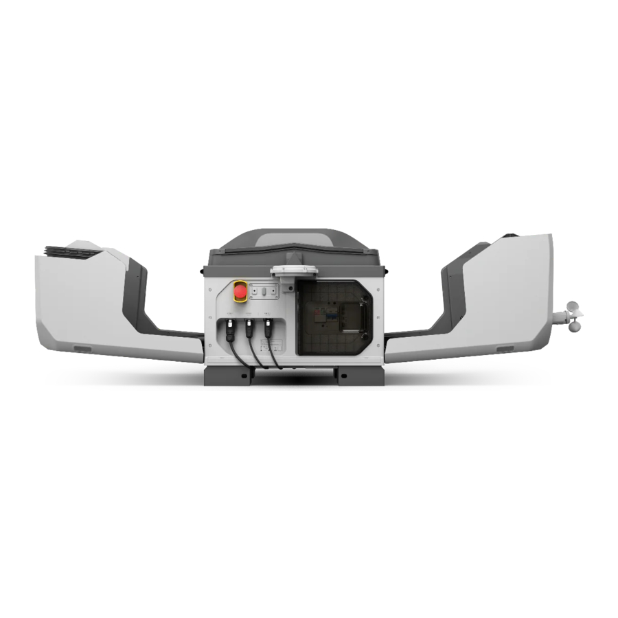
Overview

- Wind Speed Gauge
- Dock Camera
- Camera Auxiliary Light
- Rainfall Gauge
- Dock Cover
- Positioning Markers
- Landing Pad
- Aircraft Orientation Marker1

- PoE Output Port
- AC-IN Port
- Earth Wire
- Electrical Cabinet
- LAN-IN Port
- Mounting Base Brackets
- Emergency Stop Button2
- Status Indicators
- Cellular Dongle Compartment
- RTK Module
- For Vehicle-mounted Gimbal Mount
- E-Port
- Drain Pipe Hole (located underneath the dock)

- Wire Testing Terminals
- Multifunctional Button
- AC Power Switch
- USB-C Port
- Electrical Cabinet Indicators
- Close Button3
- Open Button 3

- The dock comes with a built-in charging module. Make sure that the landing pad surface is clear of any metal objects in order to avoid high temperatures that may damage the landing pad.
- The dock cover will fail to open or close if the emergency stop button is pressed.
- Press and hold the button when opening and closing the cover. Make sure that there are no obstacles blocking the dock cover. Keep a safe distance from the dock cover to avoid injury when opening or closing the dock cover.
In the Box
Check that all of the following items are included in the package. If any abnormalities, missing items, or inconsistencies are found, make a record on-site and contact your device carrier and device supplier.


User Prepared Tools and Items
The tools and items below are used during installation and configuration, prepare them in advance and ensure that the tools are in working order.


- Cables are reserved by the authorized service provider before installation. The power cable requires RVV three-core 1.5 mm outdoor sheathed cable with a cable diameter of 7-12 mm, and the Ethernet cable requires Cat 6 twisted pair cable with a cable diameter of 6-9 mm. In order to guarantee the seal is secure and that the water-resistant performance is not compromised.
- Make sure the length of the multimeter probes is greater than 18 mm in order to facilitate accurate testing of the wire terminals.
For Vehicle-mounted Deployment


- Make sure that the total load-bearing capacity of each item is greater than 165 kg.
- Make sure to use nylon locknuts and the outer diameter of the flat washer must be no less than 30 mm.
Dock Installation
Installing the Parts

- Mount the wind speed gauge module as per diagram. Make sure the connector is oriented correctly. Avoid the screws from falling through the hole into the dock cover.
- Mount the RTK module as per diagram. Gently insert the signal cable. Make sure to securely tighten all the screws.
Confirming Installation Position and Orientation
Make sure to consider the below factors before installing the dock.
- Make sure the dock camera orientation is not facing direct sunlight. Otherwise, the service life of the product and camera view may be affected due to the environmental factors.
- To avoid false detection when the aircraft lands, make sure that there are no light-colored objects similar to the shapes or visual identification markers on the landing pad within 5 m of the dock, such as white rectangles, white triangles, and H patterns.
- Place the digital level on top of installation site to measure two diagonal direction. Make sure that the surface is horizontally level with inclinations less than 3° in any direction.
Installation
Fixed-mounted Deployment
- Wear a dust mask and safety goggles when drilling holes to prevent dust from entering the eyes, nose, and throat. Pay attention to personal safety when using any electrical tools.
- When aligning the expansion bolt with the mounting base brackets, DO NOT put your hands under the mounting base brackets when moving the dock in order to avoid injury.
A concrete base or steel frame base needs to be fabricated in advance at the installation site. The following installation instructions use a concrete base as an example.

- Use the installation card to assist drilling holes and mount the expansion bolts.
- It is recommended that at least two people to carry the dock. Carefully lift the dock to the installation position and secure the mounting brackets onto the expansion bolts. Make sure to securely tighten the anti-loosening nuts.

- To perform a multi-dock task, purchase multiple docks as needed. Go to the Installation and Setup Manual to refer to the Multi-Dock Task section before installing and configuring the docks.
Vehicle-mounted Deployment
- Make sure the overall height and width of the vehicle after installing the dock comply with local regulations and registration requirements. Pay attention to the overall height to avoid damage to the product during vehicle movement.
- Be careful when carry the dock onto the vehicle. DO NOT lift the dock by carrying the RTK module to avoid damage.
- When aligning the screws with the mounting base brackets, DO NOT put your hands under the mounting base brackets when moving the dock in order to avoid injury.
- Make sure the dock cover is closed before moving the vehicle.
- Leave enough space to install the dock onto the vehicle-mounted platform (user-prepared) as per diagram. Properly orient the electrical cabinet for easy operation. For dual-dock installation, make sure to mount an air guide baffle (A) to guarantee the heat dissipation.

- Open the electrical cabinet door. Press, and then press and hold the multifunctional button to power on the backup battery. Press and hold the open button to open the dock cover. Power off the backup battery in the same way.
Correctly mount the Vehicle-mounted Gimbal Mount (optional) to the dock as per diagram. Gently insert the signal cable. Make sure to route the cables and securely tighten the screws.
Power on the backup battery. Press and hold the close button to close the dock cover. Close and lock the electrical cabinet door.

- Connect the drain pipe as per diagram. It is recommended that at least six people to carry the dock. Carefully lift the dock to the vehicle-mounted platform and secure the mounting base brackets onto the T-screws. Make sure to securely tighten the anti-loosening nuts. Use a paint marker to make marks for checking if the nuts are loose. Fasten one end of the anti-off steel wire rope to the dock using the anti-off lock and fasten the other end to a secure location.


Connecting and Powering on the Dock
Connecting the Earth Wire
The dock must be properly grounded by following the below requirements.
Make sure that the earth wire is not coiled or intertwined with the signal cables.
- Fixed-mounted Deployment: Check that the design and assembly of the earth-termination system meet the requirements before installation. Connect the earth wire to the lead-out pole of the earth electrode and tighten it with the screw and nut.

- Vehicle-mounted Deployment: Replace with user-prepared earth wire and connect it to the ground rod. Make sure the ground rod is properly grounded before each dock operation.


Connecting the Ethernet Cable
Make sure to install a data and signal surge protector device in the user computer room and ensure that it is properly grounded. Refer to the Network Requirements section in the Installation and Setup Manual for more information.

- Lead the cable near to the product. Insert the cable into the corrugated tubing and the corrugated tubing plug in sequence.
![]()
- Strictly follow the steps as per diagram to rebuild the Ethernet connector.
- Insert the Ethernet connector until a click is heard.

- Make sure the other end of the Ethernet cable is properly and securely connected to the device in the user computer room.
- Make sure the network is able to access the Internet with an upstream and downstream bandwidth greater than 20 Mbps. To ensure a better user experience, it is recommended that the bandwidth be greater than 40 Mbps.
- Refer to the Installing a Cellular Dongle (Optional) section for more information if the dock needs to access a wireless network.
- After installation, press the locking tab of the pass through connector using a flathead screwdriver to remove it from the Ethernet connector.
- When using D-RTK 3 Relay Fixed Deployment Version (sold separately), use the same method to make an Ethernet cable connector and insert to the PoE output port. Read the corresponding manual for installation and use information.
Connecting the Power Cable
- Only certified electricians can carry out above-safety-voltage operations.
- Before operation, make sure to turn off the upstream main switch in the user distribution box and place a sign near the switch prohibiting the turning on of the switch.
- Use a multimeter to measure the electrical current of the power cable. DO NOT operate with an electrical current.

- Lead the cable near to the product. Insert the cable into the corrugated tubing and the corrugated tubing plug in sequence.
![]()
- Follow the steps below to rebuild the power connector.
- Disassemble the power connector as per diagram.
- Lead the power cable through the power connector. Use the ruler pattern (printed on the accessory box) to measure the length of the cable and wires. Use a tool to remove the outer and inner insulation layers to expose the conductor of the wire. Crimp the wire ferrules onto the end of the wires.
- Loosen the screws on the inner component and insert the wire ferrules. Make sure L (live wire), N (neutral wire), and the PE (earth wire) wires are corresponding to terminals 1, 2, and 3 before tightening the screws.[1]
- Insert the internal component into the outer casing. Strictly follow the steps to tighten the tail sleeve and the tail nut in sequence.
- Insert the power connector until a click is heard.
- The color of the earth, neutral and live wires may vary by country and region. Make sure the three wires are properly and securely connected.
- Be careful not to damage the wire insulation layer when stripping the cable insulation layer.
- Check that the connection between the power cable connector and the cable is not damaged to guarantee waterresistant performance.
Wiring Connection Test
DO NOT touch the metal parts of the dock or the multimeter lead probes to avoid an electric shock.
- Turn on the upstream main switch in the user distribution box.
- Open the electrical cabinet door. Set the multimeter to 750V AC voltage range, and measure at the wire testing holes respectively. If any measurement result is inconsistent, perform troubleshooting before powering on the dock.
Wire Testing Holes Fix-mounted Deployment Vehicle-mounted Deployment N L 90-240 V 90-240 V N ![]()
<4 V ≈U ln /2 L ![]()
90-240 V ≈U ln /2 ![]()


Powering on the Dock
Checklist Before Powering On
| Checklist | Description |
| Earth Wire | □ The two ends of the earth wire have been properly connected. |
| Ethernet Cable | □ All parts of the Ethernet connector have been tightened securely. □ The Ethernet connector has been inserted to the dock securely. |
| Power Cable | □ The wire connection test has been performed and the wire sequence is correct. □ The insulation layer of the power cable has been properly covered by the tail nut. □ All parts of the power connector have been tightened securely. □ The power connector has been inserted into the dock securely. |
| The Dock | □ The dock has been installed and is stable with a tilt angle of less than 3 degrees. □ The inside of the dock is clean and tidy, without any dust or dirt, or items left inside. □ The emergency stop button of the dock has been properly pulled out and released. □ The landing pad surface is clear of any metal objects. □ For vehicle-mounted deployment, make sure the anti-off locks are connected securely. |
| The Surrounding Environment | □ The area around the dock has been cleared of packaging materials such as cardboard, foam, and plastic. □ No obstacles block the dock covers when opening. |
Powering On and Checking Operation
- Make sure the upstream main switch in the user distribution box has been turned on. Turn on the AC power switch.
- Within 30 seconds, the electrical cabinet status indicators should display as follows. Otherwise, troubleshooting is to be performed.


Dock Configuration
Getting the Device Binding Code

- Use a computer to visithttps://fh.dji.com, and log in to DJI FlightHub 2 using an account. Click to create an organization, and enter the organization page.
- Obtain the organization ID and device binding code as per diagram.
Configuring the Dock using DJI Enterprise App
- For fixed-mounted deployment, DO NOT move a configured dock. If the site changes, the dock needs to be reconfigured.
- Make sure to keep a safe distance when using the app to open the dock cover in order to avoid injury. Press the emergency stop button on the dock to stop the dock cover from opening, if necessary.
- When the aircraft is placed in the dock. Make sure to move the two blades of each motor to be at 90° with each other in order to avoid breaking the propellers when manually closing the dock cover.
Prepare the aircraft by referring to the manual included in the aircraft packaging. Place the aircraft next to the dock. Press, and then press and hold the power button to power on the aircraft.

- Use the USB-C to USB-C cable to connect the smartphone to the dock. Open the DJI Enterprise app and select the proper deployment mode. Follow the app prompts to complete the linking, activation and configuration for the dock and the aircraft. Make sure to calibrate the aircraft compass before using for the first time.
- Make sure the aircraft orientation is consistent with the arrow mark on the landing pad, and the aircraft is placed on the landing pad as shown in the diagram to complete the configuration. Dock Onsite Debugging in the app provides the dock status, the aircraft status, and operations such as testing air conditioning, controlling the dock cover, and charging the aircraft.[1]
- Disconnect the USB-C to USB-C cable. Close and lock the electrical cabinet door using screwdriver.
[1] The aircraft can be charged after it is linked with the dock. Make sure to keep the dock covers closed during charging and the landing pad surface clear of any metal objects.
- Refer to the site evaluation result, make sure to import the entry/exit route if necessary.
- The aircraft and the dock require activation before first time use. An internet connection is required for the smartphone during activation.
- For vehicle-mounted deployment, make sure to set the alternate landing site recommended at the head of vehicle.
Connecting the Remote Controller as Controller B
To ensure the safety of the flight test for the dock, the remote controller can be used to take control of the aircraft manually during flight, after connecting to the aircraft as controller B.

Controller B is supported to be used when no relay station is deployed.
Automatic Operation Test
Binding the Dock to a Project

- Enter the DJI FlightHub 2 and create a project.
- Add the dock to the specified project in the drop down box of the project as per diagram.
![information]() For vehicle-mounted deployment, if mounting two docks on one vehicle, add all docks to the same project to ensure the Multi-Drone Takeoff/Landing performs properly.
For vehicle-mounted deployment, if mounting two docks on one vehicle, add all docks to the same project to ensure the Multi-Drone Takeoff/Landing performs properly.
Performing the Flight Task
For vehicle-mounted deployment, make sure to calibrate the dock RTK in DJI FlightHub 2 before takeoff. DO NOT move the vehicle during the dock operation.
- Click Trial Flight in Device Maintenance and a task plan will be automatically created. Complete the plan name, use the default settings and start the flight.
- The dock cover will open and the aircraft will begin to perform the flight task.
- Click Project > Team
![]() to view the operation status, warning information, and live view.
to view the operation status, warning information, and live view. - After completing the flight task, the aircraft will land to the dock and the dock cover will close.
- To use the trial flight, make sure the dock is bound to a project, the dock status is Idle, and use a project admin account.
- During the flight task, press the emergency stop button to test if the aircraft can fly to the alternate landing site.
Checklist before Leaving
Before leaving the site, make sure to check the following items.
□ The HMS of DJI FlightHub 2 has no abnormal alarm.
□ The screws of the wind speed gauge module and the RTK module are tightened securely.
□ Check the wind speed gauge data displayed in DJI FlightHub 2 by rotating the wind speed gauge.
□ The surface of the dock cover, rainfall gauge and landing pad are clear of dirt and foreign matter.
□ The AC power switch in the electrical cabinet is turned on.
□ Make sure the aircraft is correctly placed on the landing pad and the aircraft heading is aligned with the arrow mark.
□ Make sure the covers of all the ports have been closed properly if not used.
□ Make sure the screws are securely tightened with the provided tool if any official payloads are mounted on the aircraft.
□ The lenses of the vision systems, gimbal cameras, glass of the infrared sensors, and auxiliary lights are clean. □ Dock cover is closed.
□ The electrical cabinet door is closed and locked.
□ The aircraft alternate landing site test has been completed.
Installing a Cellular Dongle (Optional)
DJI Cellular Dongle 2 is used as an example.
Operate with caution. Avoid pulling the cables or crushing the cables by the compartment cover. Make sure that the indicator on the dongle is green.

Status Indicators
| Normal States | |
| Blinks white | The dock is working normally and the aircraft is ready to take off. |
| Blinks blue | The dock and the aircraft are linking, and the buzzer emits a short beep. |
| Blinks green | The aircraft has taken off from the dock and is performing a flight task. |
| Solid blue | The dock is updating or debugging (including remote debugging and on-site debugging). |
| Warning States | |
| Blinks red | The dock covers are moving or the aircraft is taking off or landing, and the buzzer emits a long beep. |
| Blinks red and yellow alternately | The emergency stop button on the dock is pressed. |
Scan the QR code or go to the address listed to download the app, watch the tutorial videos, and read the manuals.
Make sure to contact an authorized service provider for installation. There may be potential safety hazards if the product is installed by the user. Contact the official support for more information on authorized service providers.

Documents / Resources
References
Download manual
Here you can download full pdf version of manual, it may contain additional safety instructions, warranty information, FCC rules, etc.
Advertisement


Need help?
Do you have a question about the DOCK 3 and is the answer not in the manual?
Questions and answers