SFA Sanicom 1 / 2 Manual
- Operating & installation manual (69 pages) ,
- Manual (13 pages) ,
- Installation instructions manual (10 pages)
Advertisement
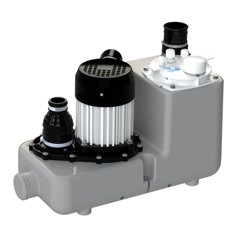
APPLICATION
Sanicom® is a lifting pump for wasterwater originating from sinks, clothes washing machines, dishwashers, showers or baths and basins, used in private or commercial applications (restaurants, hairdressings salons,...).
The unit has a high performance level, and is safe and reliable, provided all the rules for installation and maintenance in this notice are strictly followed
DESCRIPTION
OPERATING PRINCIPLE
Sanicom® 1 contains 1 pump.
The tank is equipped with 2 tubes, one controls motor activation, and the second controls the alarm system.
Sanicom® 2 contains two independent pumps. Both pumps operate alternately to ensure even ware. In case of surcharge operation, both motors run simultaneously (or if one pump fails, the other takes over).
The tank is equipped with three dip tubes, two of which control motor activation, and the third controls the alarm system.
TECHNICAL DATA
| Sanicom® 1 | Sanicom® 2 | |
| Type | P 95 | R 90 |
| Maximum vertical pumping height | 8 m | 10 m |
| Voltage | 220-240 V 220-240 V | |
| Frequency | 50-60 Hz | 50-60 Hz |
| Maximum power consumption | 750 W | 3 000 W |
| Maximum current consumption | 3.3 A | 13 A |
| Electrical class | I | I |
| Protection index | IP X4 | IP X4 |
| Max. temperature permissible 5 min/h | 90°C | 90°C |
| Net weight | 10 kg | 26 kg |
INSTALLATION
The Sanicom® installation must comply with EN12056-4 standards. All work to install the equipment, put it into service and carry out maintenance must be done by a qualified professional specialist.
FITTING
- The space in which Sanicom® is installed must be large enough to leave at least 600mm around the unit for easy maintenance. This space must be well lit, ventilated, and must never be immersed in water and must be protected from frost.
- Isolation valves should be fitted to the inlet pipework and discharge pipework to isolate the unit in case of the need for service.
- This discharge pipe must be designed so as to prevent back-flow from the sewers. Backflow is avoided by installing an anti-backflow loop located above the back-flow level.
COMMENT: UNLESS OTHERWISE STATED LOCALLY, THE BACKFLOW LEVEL CORRESPONDS TO THE LEVEL OF THE ROAD OR PAVEMENTS,... - The pumping station must always be ventilated so that the tank is always at atmospheric pressure. The ventilation must be completely free and air must flow in both directions (no diaphragm valve fitted). Do not connect to a mechanically controlled ventilator.
ELECTRICAL CONNECTION
Do not make the electrical connection until the final connections are completed
COMMISSIONING
Once the plumbing and electrical connections have been made, check that the connections are watertight by letting water flow successively through each inlet used. Make sure that the unit is operating correctly by carrying out at least two start cycles with water to test the system.
USE
Sanicom® is designed for disposing of greywater originating from sinks, clothes washing machines, dishwashers, showers or baths and basins. Sanicom® can pump out hot water.
Do not dispose of concentrated chemical products (acids, solvents, bases, oxidants, reducers, etc.) into sanitary ware connected to the Sanicom®.
In the event of power failure, stop all water flow to the appliances connected to the Sanicom®.
In case of discharge of greasy effluents, the use of a degreasing tank is essential.
CONTROL BOX OPERATION
SANICOM 1: CONTROL KEYPAD OPERATION
- General alarms
Mains alarm:
If the LED is off, there is no power supply.
Level alarm:
If the water level inside the device is abnormally high, the high level diptube microswitch will activate the motor and the alarm LED lights up red. If this LED flashes red, it indicates a detection problem for the normal water level (Long dip tube).
Time alarm:
If the motor runs continuously for more than 1 minute, the red LED alarm lights up.
![]()
- Reset alarm
The button on the keypad will only allow you to turn off the red LED (it will turn green) if the problem that triggered the alarm has been resolved.

SANICOM 2: REMOTE CONTROL BOX OPERATION
- General alarms
Mains alarm:
In case of power failure (or when unplugging the device): the buzzer is triggered + the red alarm LED lights up + the yellow mains LED flashes.
Level alarm:
If the water level inside the device is abnormally high: the buzzer is triggered + the red alarm LED lights up + both motors start-up. If this LED flashes red, it indicates a detection problem for the normal water level (Long dip tube).
Time alarm:
If one of the two motors runs for more than 1 minute: the buzzer is triggered + the red alarm LED lights up + the other motor starts-up.
![]()
- General alarm reset
If the problem that triggered an alarm above disappears, the buzzer stops, but the red alarm LED remains on until the next normal cycle.
One of the two keypad keys will stop the buzzer in any cases, but it will only turn off the red LED if the problem that caused the alarm has been resolved. The alarms of the remote box also remain active until the problem has been solved. This prevents the system from being «abandoned» in default.
NOTE: Option of connection to an external alarm (Sanicom®2).
Option of externalising the alarm signal. Dry contact (no voltage) NO (normally open) operated by a relay. Alarm contact can connected to a powered system. This contact closes as soon as the station is in alarm mode (except in the case of area alarm) and remains closed as long as the alarm sounds.
![]()


STANDARD
This piece of equipment complies with the EN 12050-2 standard (Lift station for effluents not containing faecal matter) and European Low Voltage Directive.
INSPECTION AND MAINTENANCE
- Inspection
The proper running of the wastewater lifting station must be checked by user once a month observing at least two starting cycles. - Maintenance
The lifting station has to be regularly maintained by a qualified person. Intervals should:- Every 3 months for lifting stations installed in commercial premises
- Every 6 months for lifting stations installed in collective buildings
- Once a year for lifting stations installed in individual houses During maintenance, the following should be done:
- Check the watertightness of connections by checking pipework to and from the lifting station
- Activate the gate valves, check their smooth function and their watertightness ( grease if necessary)
- Open and clean up the non return-valve system, check it is functioning correctly
- Clean up the pumping system and its connections, check the impeller and the cutting system (for macerating pumps)
- Clean up the inside of the collecting tank
- Visually check the lifting station's electrical control box functions.
Once the checks have been made, restart the lifting station in compliance with the manual instructions to check its proper running.
A report should be issued detailing the checks and any notable points.
If non-compliances that cannot be solved have been found, the qualified person in charge of the maintenance work has to immediately inform the lifting station's user.
- Maintenance contract
It is advised to the users to establish a maintenance contract for regular maintenance and checking.
FAULT FINDING GUIDE
 DISCONNECT THE STATION BEFORE ANY INTERVENTION!
Alarm on Sanicom® 1 device:
| FAULT DETECTED | POSSIBLE CAUSES | ACTION TO BE TAKEN |
Flashing red alarm LED |
|
|
Steady red alarm LED |
|
|
LED off |
|
|
Alarm on the Sanicom® 2 control box:
| FAULT DETECTED | POSSIBLE CAUSES | ACTION TO BE TAKEN |
Siren + flashing red general alarm LED |
|
|
Siren + steady red general alarm LED |
|
|
Siren + general alarm LED + flashing yellow mains LED |
|
|
DISMANTLING
INSTRUCTIONS RESERVED EXCLUSIVELY FOR QUALIFIED PROFESSIONAL SPECIALISTS
If one of the motors cannot be made to operate correctly, use of that motor can be "disabled" by setting the corresponding switch on the board (P1, P2: Switches 1 and 2 for motors 1 and 2).
The motor thus "disabled" can be removed. The unit operates on the other motor.
DEFINITION OF WARNING SIGNS
 Warning indication of a risk for the machine or its operator.
Warning indication of the presence of a risk of electrical origin
DISCONNECT THE STATION BEFORE ANY INTERVENTION!
Documents / ResourcesDownload manual
Here you can download full pdf version of manual, it may contain additional safety instructions, warranty information, FCC rules, etc.
Advertisement


Need help?
Do you have a question about the Sanicom 1 and is the answer not in the manual?
Questions and answers