
Related Manuals for Toshiba TS605


Summary of Contents for Toshiba TS605
- Page 1 MOBILE COMMUNICATIONS DIVISION CUSTOMER SERVICES TS605 / TS2050 Technical Service Manual Version 1.0 22/11/2006 Created by Konrad Szombara Page 1 of 103...
-
Page 2: Table Of Contents
MOBILE COMMUNICATIONS DIVISION CUSTOMER SERVICES INDEX PAGE 1.0 GENERAL ADVICE 1.1 CUSTOMER CARE SOLUTIONS 1.2 ESD PROTECTION 2.0 HANDSET SPECIFICATION AND INTRODUCTION 2.1 HANDSET SPECIFICATION 2.1.1 HARDWARE 2.1.2 SOFTWARE 2.1.3 PHYSICAL 2.1.4 VIDEO 2.1.5 OTHERS 2.1.6 PRODUCT OVERVIEW 2.2 INTERFACES 2.2.1 SIM CARD INTERFACE 2.2.2 MEMORY CARD INTERFACE 2.2.3 BATTERY INTERFACE... - Page 3 MOBILE COMMUNICATIONS DIVISION CUSTOMER SERVICES INDEX PAGE 5.0 SOFTWARE DOWNLOAD 5.1 SOFTWARE DOWNLOAD 5.1.1 DOWNLOAD CABLES 5.1.2 DOWNLOAD TOOL 5.1.3 EQUIPMENT SETTING 5.1.4 MAIN PROGRAM INTERFACE 5.1.5 BACKUP TOOL 6.0 SYSTEM MODULE AND USER INTERFACE 6.1 TECHNICAL DESCRIPTION 6.1.1 RF OVERVIEW 6.1.2 RF FUNCTION BLOCK DIAGRAM 6.1.3 FREQUENCY PLAN 6.1.4 TRANSMITTER...
- Page 4 MOBILE COMMUNICATIONS DIVISION CUSTOMER SERVICES INDEX PAGE 7.0 TROUBLE SHOOTING 7.1 MAIN TROUBLE SHOOTING DIAGRAM 7.1.1 NO POWER UP 7.1.2 FLASH FAILED 7.1.3 WILL NOT READ SIM CARD 7.1.4 POOR SERVICE 7.1.5 WILL NOT CHARGE 7.1.6 LCD FAILURE 7.1.7 BUZZER FAULT 7.1.8 VIBRATOR FAULT 7.1.9 FAULTY KEYPAD 7.1.10 FAULTY RTC...
-
Page 5: General Advice
MOBILE COMMUNICATIONS DIVISION CUSTOMER SERVICES 1.0 GENERAL ADVICE Version 1.0 22/11/2006 Created by Konrad Szombara Page 5 of 103... -
Page 6: Customer Care Solutions
4- All documentation within this service manual must remain confidential and should not be shared with any unknown 3 party, without written consent from Toshiba MCD, UK. Cautions 1- Servicing and alignment must be undertaken by qualified personnel only. -
Page 7: Esd Protection
CUSTOMER SERVICES 1.2 ESD (Electro Static Discharge)PROTECTION SERVICE REQUIRMENTS 1- Toshiba require that all TPSV’s ensure that the technicians work bench has sufficient ESD protection. 2- Accessories such as batteries, chargers, multimedia cards and sim cards can be replaced in normal conditions (Non ESD protected environment). -
Page 8: Handset Specification And Introduction
MOBILE COMMUNICATIONS DIVISION CUSTOMER SERVICES 2.0 HANDSET SPECIFICATION AND INTRODUCTION Version 1.0 22/11/2006 Created by Konrad Szombara Page 8 of 103... -
Page 9: Handset Specification
MOBILE COMMUNICATIONS DIVISION CUSTOMER SERVICES 2.1 HANDSET SPECIFICATION 2.2.1 HARDWARE Item Description Remark Frequency EGSM-900(880MHz– 960MHz). Three-band GSM-1800(1710MHz– 880MHz) PCS-1900(1850MHz– 990MHz) 1.93" 176X220 TFT Citizen Display 1.3 Mega CMOS Camera w/o Marco Vender: CSR Chipset: BC3-ROM Support: v1.2 Bluetooth V1.2 Power Class: Class 2 or 3 Max Size of data of phone memory : 350KB... -
Page 10: Software
CLDC 1.0 + JSR -120 Wireless Messaging API + JSR-118 MIDP 2.0) JSR-185 JTWI (Conditional: JSR-135 MMAPI (mobile multimedia API) + JSR-139 CLDC 1.1) T9 Input 6.1.3 TBD, define by Toshiba Text Input 1.1.2 ExtendSI SynML DS SynML DM POP3/SMTP Email QR code recognition Version 1.0 22/11/2006... -
Page 11: Physical
MOBILE COMMUNICATIONS DIVISION CUSTOMER SERVICES 2.1.3 PHYSICAL SPECIFICATION Item Description Remark Detail Features Air Link Protocol Class10 GPRS ---- EDGE Physical Features Candy Bar Form Factor 113*47*10.3mm Dimension 84g (AL) ; 81g(Ma) Weight Display Features 176X220 (w*h) Resolution 1.93" Dimension LCD Technology Transmissive type w/o Reflective Type... -
Page 12: Video
MOBILE COMMUNICATIONS DIVISION CUSTOMER SERVICES 2.1.4 VIDEO SPECIFICATION Item Description Remark Video Codec Feature Digital Zoom capability BMP, JPEG, GIF, PNG Still image output format CIF @ 15fps Video Decode Capability (MPEG4/H263) Video Decode Capability (H264/AAC) CIF @ 15fps Video Encode Capability (MPEG4/AMR) Video Phone (MPEG4/H263) Streaming (Progressive... -
Page 13: Others
MOBILE COMMUNICATIONS DIVISION CUSTOMER SERVICES 2.1.5 OTHERS Description Remark Item STK Release 98 STK Release 99 STK Class SIM Lock V. 4.2 (excluded IN & CPHS CSP) Phase 1 & 2 USSD Multimedia Message SMS - Cell Broadcast OMA 1.1 i-Mode POP3/SMTP E-Mail... -
Page 14: Voice Recognition
MOBILE COMMUNICATIONS DIVISION CUSTOMER SERVICES 2.1.5 OTHERS CONTINUED Description Remark Item Wifi 7480KB for user memory Mass Storage Java Doja JTWI 1.0 JSR-75 PDA PIM & FC JSR-82 Bluetooth API JSR-120 WMA 1.0 JSR-184 3D (OpenGL) JSR-205 WMA 2.0 JSR-234 Advanced Multimedia Supplements JSR-248 Mobile Service Architecture for CLDC... -
Page 15: Product Overview
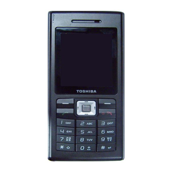
CUSTOMER SERVICES 2.1.6 PRODUCT OVERVIEW The TS605/TS2050, is a slim and very stylish product that boast all of the features that you would expect as standard. Although the product incorporates a simple 1.3 mega pixel camera, the display really does show off the high quality of images with excellent detail. -
Page 16: Interfaces
MOBILE COMMUNICATIONS DIVISION CUSTOMER SERVICES 2.2 INTERFACES 2.2.1 SIM CARD INTERFACE Your SIM card identifies your phone on the network and stores your details, including your PIN, call history, and subscription information. It can also be used to store some phone book data. You should only remove your SIM card when absolutely necessary. - Page 17 MOBILE COMMUNICATIONS DIVISION CUSTOMER SERVICES Version 1.0 22/11/2006 Created by Konrad Szombara Page 17 of 103...
-
Page 18: Memory Card Interface
MOBILE COMMUNICATIONS DIVISION CUSTOMER SERVICES 2.2.2 MEMORY CARD INTERFACE Your Phones supports a microSD card up to 1GB. The memory card slot is located under the battery. The battery cover is located on the rear of the phone. Inserting / Removing the Memory slot Turn to the back of your phone to locate your battery room. - Page 19 MOBILE COMMUNICATIONS DIVISION CUSTOMER SERVICES Version 1.0 22/11/2006 Created by Konrad Szombara Page 19 of 103...
-
Page 20: Battery Interface
MOBILE COMMUNICATIONS DIVISION CUSTOMER SERVICES 2.2.3 BATTERY INTERFACE The battery included with your phone is not charged. Before you can switch on your phone for the first time, you need to install the phone's battery and charge it. Inserting or Changing the Battery To insert or change the battery: Version 1.0 22/11/2006 Created by Konrad Szombara... -
Page 21: Charging The Battery
MOBILE COMMUNICATIONS DIVISION CUSTOMER SERVICES 2.2.4 Charging the Battery To charge a battery: During charging, there will no indication on the phone screen. Please keep the phone charge for a white before you disconnect the charger. Disconnecting the charger To disconnect the charger, grip it tightly and pull. You should disconnect the charger from the power outlet before disconnecting the charger from the phone. -
Page 22: Charging Indicator
MOBILE COMMUNICATIONS DIVISION CUSTOMER SERVICES 2.2.5 Charging Indicator The first time you charge your battery, you should leave it charging for 8 hours. The battery only achieves optimum performance after two or three complete charges. When the battery power is low, the phone starts beeping and "Battery Low" will be displayed. -
Page 23: Handset User Interface
MOBILE COMMUNICATIONS DIVISION CUSTOMER SERVICES 2.3 HANDSET UI 2.3.1 HANDSET DESCRIPTION Version 1.0 22/11/2006 Created by Konrad Szombara Page 23 of 103... -
Page 24: Key Functions
MOBILE COMMUNICATIONS DIVISION CUSTOMER SERVICES 2.3.2 KEY FUNCTIONALITY Version 1.0 22/11/2006 Created by Konrad Szombara Page 24 of 103... - Page 25 MOBILE COMMUNICATIONS DIVISION CUSTOMER SERVICES Version 1.0 22/11/2006 Created by Konrad Szombara Page 25 of 103...
-
Page 26: Display Concept
MOBILE COMMUNICATIONS DIVISION CUSTOMER SERVICES 2.3.3 Display Concept – Main Icon Description Signal Strength (lower to high) Roaming Keypad lock Appointments Bluetooth (active/connecting) Phone set to mute/Vibrate Alarm Set Message indicator Battery level ( empty to full) Headset Version 1.0 22/11/2006 Created by Konrad Szombara Page 26 of 103... -
Page 27: Main Menu
MOBILE COMMUNICATIONS DIVISION CUSTOMER SERVICES 2.3.4 MAIN MENU Version 1.0 22/11/2006 Created by Konrad Szombara Page 27 of 103... -
Page 28: Menu Structure
MOBILE COMMUNICATIONS DIVISION CUSTOMER SERVICES Menu Structure Main Menu 2nd Level Main 2nd Level Menu Entertainment Games Settings General Composer Display Sounds Contacts View contacts Connectivity View groups Browser Homepage Special Bookmarks numbers Settings Quick call Tools Scheduler Advanced Alarm Memory status Appointments My Player... -
Page 29: Mmi Test
MOBILE COMMUNICATIONS DIVISION CUSTOMER SERVICES 2.4 MMI TEST The MMI test application is provided to check or adjust the mobile workability. Dial *#369#* to enter the test mode. Please notice the items 4,5,6 are for production and for special purpose, don’t change the default value arbitrarily or may cause mobile malfunction. -
Page 30: Mechanical Concept
MOBILE COMMUNICATIONS DIVISION CUSTOMER SERVICES MECHANICAL CONCEPT Version 1.0 22/11/2006 Created by Konrad Szombara Page 30 of 103... -
Page 31: Exploded View
MOBILE COMMUNICATIONS DIVISION CUSTOMER SERVICES 3.1 Exploded View Version 1.0 22/11/2006 Created by Konrad Szombara Page 31 of 103... - Page 32 MOBILE COMMUNICATIONS DIVISION CUSTOMER SERVICES EXPLODED VIEW CONTINUED Version 1.0 22/11/2006 Created by Konrad Szombara Page 32 of 103...
-
Page 33: Mechanical Spare Parts List
MOBILE COMMUNICATIONS DIVISION CUSTOMER SERVICES 3.2 SPARE PARTS LIST - MECHANICAL Ref No Description Part Number TOP CASE ASSY VI5 TOP CASE VI5 33VI5TC0I01 ANTENNA FPC DQ663196502 BASE CASE ASSY VI5 SILVER EAVI5002017 MIDDLE CASE ASSY VI5 36VI5MC0I06 RECEIVER (SPK 320OHM) DN1D109B002 SPEAKER 8 OHM 97DB(0.5W,DSH929-001) DNDSH929001... -
Page 34: Spare Parts Photo
MOBILE COMMUNICATIONS DIVISION CUSTOMER SERVICES 3.3 SPARE PARTS - PHOTO Version 1.0 22/11/2006 Created by Konrad Szombara Page 34 of 103... -
Page 35: Disassembly And Reassembly Procedure
MOBILE COMMUNICATIONS DIVISION CUSTOMER SERVICES DISASSEMBLY REASSEMBLY PROCEDURE Version 1.0 22/11/2006 Created by Konrad Szombara Page 35 of 103... -
Page 36: Disassembly
MOBILE COMMUNICATIONS DIVISION CUSTOMER SERVICES 4.1 DISASSEMBLY Purpose:Change defect mechanical parts Tools: Black Sticker, T5 and Tweezers Tools :T5 and Tweezers and Black Sticker Tweezers Black Sticker Remove the Battery Cover Remove the Battery Version 1.0 22/11/2006 Created by Konrad Szombara Page 36 of 103... - Page 37 MOBILE COMMUNICATIONS DIVISION CUSTOMER SERVICES Take out Car kit rubber Release 2 screws Using Black Sticker to lift up the Top Case from the Base Case. Version 1.0 22/11/2006 Created by Konrad Szombara Page 37 of 103...
- Page 38 MOBILE COMMUNICATIONS DIVISION CUSTOMER SERVICES Using Black Sticker to lift up the Top Case form the right side. Using Black Sticker to lift up the Top Case from the left side. (be care do not damage the Bluetooth Antenna) Let the Top Case upward. And remove the Key Set.
- Page 39 MOBILE COMMUNICATIONS DIVISION CUSTOMER SERVICES The Motor (vibrator) can be pulled up when use tweezers. Remove the receiver Release 2 screws of middle case Version 1.0 22/11/2006 Created by Konrad Szombara Page 39 of 103...
- Page 40 MOBILE COMMUNICATIONS DIVISION CUSTOMER SERVICES Separate Key PCB from the Antenna Holder. Separate the Antenna Holder from Base case Use Black Sticker to raise the PCB module from the Base Case. Use Black Sticker to raise the PCB module from the Middle Case.
- Page 41 MOBILE COMMUNICATIONS DIVISION CUSTOMER SERVICES tear off mylar of Speaker Remove the speaker. (Carefully not to damage the SPK’s pin.) Version 1.0 22/11/2006 Created by Konrad Szombara Page 41 of 103...
- Page 42 MOBILE COMMUNICATIONS DIVISION CUSTOMER SERVICES Detach the Key PCB coaxial cable head from the Key PCB & M/B Version 1.0 22/11/2006 Created by Konrad Szombara Page 42 of 103...
-
Page 43: Reassembly
MOBILE COMMUNICATIONS DIVISION CUSTOMER SERVICES 4.2 REASSEMBLY Assemble Middle Case on Base Case Make sure hook on the position as shown Assemble Antenna Holder on Base Case Version 1.0 22/11/2006 Created by Konrad Szombara Page 43 of 103... - Page 44 MOBILE COMMUNICATIONS DIVISION CUSTOMER SERVICES Tear off paper of speaker. Place the Speaker on the Base Case. (remind:be care the pins of speaker, don’t damage) Stick Mylar on Speaker Stick Mylar on USB Conn as shown Version 1.0 22/11/2006 Created by Konrad Szombara Page 44 of 103...
- Page 45 MOBILE COMMUNICATIONS DIVISION CUSTOMER SERVICES Mount the Key PCB coaxial cable head on the Key PCB & M/B. Tear off protect film of CMOS Version 1.0 22/11/2006 Created by Konrad Szombara Page 45 of 103...
- Page 46 MOBILE COMMUNICATIONS DIVISION CUSTOMER SERVICES Assemble USB into Base Case then assemble M/B to base case as shown Tear off tape paper of base case as shown then assemble K/B on base case Pls push the coaxial (antenna) cable to the bottom of M/B Version 1.0 22/11/2006 Created by Konrad Szombara...
- Page 47 MOBILE COMMUNICATIONS DIVISION CUSTOMER SERVICES Tighten 2 screws on middle case (Torque: 0.5+/- 0.1kgsf/cm2) Tear off tape paper of Receiver then assemble on Top Case Tear off tape paper of Motor then assemble on Top Case as shown Version 1.0 22/11/2006 Created by Konrad Szombara Page 47 of 103...
- Page 48 MOBILE COMMUNICATIONS DIVISION CUSTOMER SERVICES Place Keyset on Top Case Assemble the Top Case with the Base Case as shown. (Be care the Motor line) Take care and do not damage Bluetooth Antenna Version 1.0 22/11/2006 Created by Konrad Szombara Page 48 of 103...
- Page 49 MOBILE COMMUNICATIONS DIVISION CUSTOMER SERVICES Position Top Case hook as shown Tighten 2 screws (Torque: 0.5+/- 0.1kgsf/cm2) Version 1.0 22/11/2006 Created by Konrad Szombara Page 49 of 103...
- Page 50 MOBILE COMMUNICATIONS DIVISION CUSTOMER SERVICES Tear off tape paper of Main Lens Glue Stick on the main Lens shielding Clean the LCD and Main Lens Then assemble LCD Main Lens Tear Cmos lens tape paper Version 1.0 22/11/2006 Created by Konrad Szombara Page 50 of 103...
-
Page 51: Install The Battery
MOBILE COMMUNICATIONS DIVISION CUSTOMER SERVICES Stick CMOS Lens Assemble Carkit Rubber as shown Install the Battery Version 1.0 22/11/2006 Created by Konrad Szombara Page 51 of 103... - Page 52 MOBILE COMMUNICATIONS DIVISION CUSTOMER SERVICES Position the Battery Cover Version 1.0 22/11/2006 Created by Konrad Szombara Page 52 of 103...
-
Page 53: Software Download
MOBILE COMMUNICATIONS DIVISION CUSTOMER SERVICES SOFTWARE DOWNLOAD Version 1.0 22/11/2006 Created by Konrad Szombara Page 53 of 103... -
Page 54: Download Cables
MOBILE COMMUNICATIONS DIVISION CUSTOMER SERVICES 5.1 SOFTWARE DOWNLOAD 5.1.1 DOWNLOAD CABLES Version 1.0 22/11/2006 Created by Konrad Szombara Page 54 of 103... -
Page 55: Download Tool
MOBILE COMMUNICATIONS DIVISION CUSTOMER SERVICES 5.1.2 DOWNLOAD TOOL Core Software Download Mapping Language Pack Header (encrypted) Download Setting (Mem. address, FFS...), PMC code MBF file Agent (Encrypted Raw Data) Target (Encrypted Raw Data) Version 1.0 22/11/2006 Created by Konrad Szombara Page 55 of 103... -
Page 56: Equipment Setting
MOBILE COMMUNICATIONS DIVISION CUSTOMER SERVICES 5.1.3 EQUIPMENT SETTING Handset D/L Cable • Keep handset off before downloading software • Endure that battery capacity is suitable for duration of download procedure Version 1.0 22/11/2006 Created by Konrad Szombara Page 56 of 103... -
Page 57: Main Program Interface
MOBILE COMMUNICATIONS DIVISION CUSTOMER SERVICES 5.1.4 MAIN PROGRAM INTERFACE Version 1.0 22/11/2006 Created by Konrad Szombara Page 57 of 103... - Page 58 MOBILE COMMUNICATIONS DIVISION CUSTOMER SERVICES When you have connected the cable to the handset, switch it on and the USB connection will detect automatically. 1 – Load the specific configuration file and check the configuration 2 – Wait until “Press Power is showing 3 –...
-
Page 59: Backup Tool
MOBILE COMMUNICATIONS DIVISION CUSTOMER SERVICES 5.1.5 BACKUP TOOL Program Functions Clear: Erase all user data Backup: Copy the user data to PC. The data is saved as an encrypted file with a .mot extension, under the tool installed directory Restore: restore user data to handset Backup Tool Procedure 1 –... -
Page 60: System Module And User Interface
MOBILE COMMUNICATIONS DIVISION CUSTOMER SERVICES SYSTEM MODULE USER INTERFACE Version 1.0 22/11/2006 Created by Konrad Szombara Page 60 of 103... -
Page 61: Technical Description
MOBILE COMMUNICATIONS DIVISION CUSTOMER SERVICES 6.1 TECHNICAL DESCRIPTION 6.1.1 RF OVERVIEW INTRODUCTION General Specifications The telephone is a Tri-Band product. The transmit and receive bands for the mobile are given in the table below: E-GSM 900 880-915 MHz 925-960 MHz GSM 1800 1710-1785 MHz 1805-1880 MHz... -
Page 62: Rf Function Block Diagram
MOBILE COMMUNICATIONS DIVISION CUSTOMER SERVICES 6.1.2 RF FUNCTION BLOCK DIAGRAM Version 1.0 22/11/2006 Created by Konrad Szombara Page 62 of 103... -
Page 63: Frequency Plan
MOBILE COMMUNICATIONS DIVISION CUSTOMER SERVICES 6.1.3 FREQUENCY PLAN The TX frequency plan is shown below TX frequency TX frequency TX IF TX RF LO plan 1459.59- EGSM 900 880.2-914.8MHz 88.46-114.35MHz 1543.725MHz 1710.2- 90.316- 1354.737- GSM 1800 1784.8MHz 104.776MHz 1414.482MHz 1850.2- 97.379- 1460.684- PCS 1900... -
Page 64: Transmitter
MOBILE COMMUNICATIONS DIVISION CUSTOMER SERVICES 6.1.4 TRANSMITTER SKY77328 SKY74117 Figure Transmitter block diagram TX path is a translation loop architecture consisting of an IQ modulator, integrated high power VCO, offset mixer, programmable divider, PFD, charge pump, and power amplifier with its control circuit. The device consists of an In-phase and Quadrate (I/Q) modulator within a frequency translation loop designed to perform frequency up-conversion with high output spectral purity. -
Page 65: Receiver
MOBILE COMMUNICATIONS DIVISION CUSTOMER SERVICES 6.1.5 RECEIVER Figure Receiver block diagram RX path is a direction down conversion architecture that eliminates the need for Intermediate Frequency (IF) components. The device includes three bands integrated LNAS, a quadrate demodulator, baseband amplifier circuit with I/Q outputs and three stages of DC-offset correction. -
Page 66: Baseband Overview
MOBILE COMMUNICATIONS DIVISION CUSTOMER SERVICES 6.2 BASEBAND OVERVIEW 6.2.1 INTRODUCTION The baseband block of the handset performs the following functions: Equalization Channel coding / decoding Speech coding / decoding Data Encryption Layer 1, 2 and 3 software tasks Man Machine interface (MMI) System Interface SIM Interface and Management Audio and Tone Generation... - Page 67 MOBILE COMMUNICATIONS DIVISION CUSTOMER SERVICES Digital Baseband Processor GSM processor ADI AD6527B Package 204 -Ball CSPBGA Features Complete single chip GSM Programmable Digital Baseband Processor divided into three main subsystems: 1.Control processor subsystem including 32-bit MCU ARM7TDMI control processor 58.5 MHz operations at 1.8V 1Mb on-chip System SRAM Memory 2.
-
Page 68: Cpu Memory
MOBILE COMMUNICATIONS DIVISION CUSTOMER SERVICES 6.2.2 CPU MEMORY To reduce component space, the phone uses a BGA package with Dual operation Flash memory and SRAM MCP. The following memory configuration is used: 256Mbits Flash memory organized as 16M * 16bits 64Mbits Pseudo RAM organized as 4M * 16 bits... -
Page 69: Switches
MOBILE COMMUNICATIONS DIVISION CUSTOMER SERVICES 6.3 SWITCHES 6.3.1 KEYPAD The keypad matrix contains 4 rows and 5 columns, allowing 20 keys to be scanned. When a key is pressed, a keypad interrupt is generated. Then system scans each column in turn and reads which row is active to determine which key is pressed. -
Page 70: Audio System
MOBILE COMMUNICATIONS DIVISION CUSTOMER SERVICES 6.4 AUDIO SYSTEM Figure Audio system block diagram AD6537B is a complete mixed-signal baseband processor that combines all of the data converters and power supply regulators required for GSM 900 /GSM 850 /DCS 1800 / PCS 1900 mobile on a single device, including HSCSD and GPRS. -
Page 71: Voice Band Codec
MOBILE COMMUNICATIONS DIVISION CUSTOMER SERVICES 6.4.1 VOICE BAND CODEC Chipset ADI AD6537B Package 148-Ball LFBGA Baseband Transmit Section GMSK Modulator channel & Q-channel Transmit DACs and Filters Power Ramping DAC Baseband Receive Section channel and Q-channel Receive ADCs and Filters Auxiliary Section Voltage Reference Automatic Frequency Control DAC... -
Page 72: Microphone
MOBILE COMMUNICATIONS DIVISION CUSTOMER SERVICES About handset power management, AD6537B is designed to supply all the required power in the platform. It provides seven regulator outputs, including VCORE (1.8V), VMEM (2.93V), VEXT (2.93V), VABB (2.45V), VRTC (1.8V), VCTCXO (2.75V), VSIM (2.85V), and VMIC (2.75V). VCORE and VMEM supply the power of all digital signals and VABB supplies all the analog power. -
Page 73: Speaker
MOBILE COMMUNICATIONS DIVISION CUSTOMER SERVICES 6.4.4 SPEAKER A second speaker is housed in the back case for melodies and ring tones. 6.5 POWER MANAGEMENT The block diagram of power management sub-system is shown below: Memory VMEM Power on detection VBAT and latching VCORE Battery... -
Page 74: Power On Sequence
MOBILE COMMUNICATIONS DIVISION CUSTOMER SERVICES 6.5.1 POWER ON SEQUENCE When the user presses the power key, KEYON pin of AD6537B is pulled low; all the LDOs required for system boot will be turned on at the same time. Then AD6537B pull low the KEYROW4 pin of AD6527B by KEYOUT pin, and system monitors this pin for 2 seconds to make sure the key event is not a key mis- pressing. -
Page 75: Power Source
MOBILE COMMUNICATIONS DIVISION CUSTOMER SERVICES 6.5.2 POWER SOURCE The battery used is a single Lithium-Ion (Li-Ion) cell with a nominal voltage of 3.7 V and 700-mAh capacity. T Li-Ion type of battery has an advantage in weight and size over Nickel Metal Hydride (NiMH) cells. 6.5.3 REGULATOR CONTROL The voltage regulators are enabled or disabled based on the remaining capacity of the battery. - Page 76 MOBILE COMMUNICATIONS DIVISION CUSTOMER SERVICES TCXO Regulator (VTCXO): 2.8 V The TCXO regulator is intended as a supply for a temperature compensated crystal oscillator, which needs power supply with ultra-low noise. VTCXO is rated to 20 mA output current and is turned on when TCXOEN is asserted. RTC Regulator (VRTC): 1.8 V The RTC regulator is used to charge the RTC backup battery needed by real-time clock module.
-
Page 77: Trouble Shooting
MOBILE COMMUNICATIONS DIVISION CUSTOMER SERVICES TROUBLESHOOTING Version 1.0 22/11/2006 Created by Konrad Szombara Page 77 of 103... -
Page 78: Main Trouble Shooting Diagram
MOBILE COMMUNICATIONS DIVISION CUSTOMER SERVICES 7.1 MAIN TROUBLESHOOTING DIAGRAM Version 1.0 22/11/2006 Created by Konrad Szombara Page 78 of 103... -
Page 79: No Power Up
MOBILE COMMUNICATIONS DIVISION CUSTOMER SERVICES 7.1.1 NO POWER UP Cause : PCB dead or Part jammed Phone Version 1.0 22/11/2006 Created by Konrad Szombara Page 79 of 103... -
Page 80: Flash Failed
MOBILE COMMUNICATIONS DIVISION CUSTOMER SERVICES 7.1.2 FLASH FAILED Cause : PCB dead or Min. USB has broken Version 1.0 22/11/2006 Created by Konrad Szombara Page 80 of 103... -
Page 81: Will Not Read Sim Card
MOBILE COMMUNICATIONS DIVISION CUSTOMER SERVICES 7.1.3 WILL NOT READ SIMCARD Cause : PCB dead or SIM card holder has broken Version 1.0 22/11/2006 Created by Konrad Szombara Page 81 of 103... - Page 82 MOBILE COMMUNICATIONS DIVISION CUSTOMER SERVICES 7.1.4 LOW / NO SERVICE Cause : PCB dead or Antenna has broken Low Receiving Signal or can not Check SIM card setting right? Refer to (Phone can not read SIM card) connect Network Service Provider (1) Modify antenna location.
-
Page 83: Will Not Charge
MOBILE COMMUNICATIONS DIVISION CUSTOMER SERVICES 7.1.5 WILL NOT CHARGE Cause: PCB dead or Mini. USB has broken Version 1.0 22/11/2006 Created by Konrad Szombara Page 83 of 103... - Page 84 MOBILE COMMUNICATIONS DIVISION CUSTOMER SERVICES 7.1.6 FAULTY LCD Cause: PCB dead or LCD module has broken Illumination Restore factory setting Testing Fail Re-Download Refer to (Updating program is failed) (1) Repair LCD FPC Check LCD FPC ACF ? (2) Change LCD Check LCD FPC with U403 (1) Repair U403 Connecting?
- Page 85 MOBILE COMMUNICATIONS DIVISION CUSTOMER SERVICES 7.1.7 FAULTY BUZZER Cause: PCB dead or Buzzer/Receiver has broken Buzzer Restore factory setting Testing Fail Refer to (Updating program is failed) Re-Download (1) Change Component Check the SPK/Receiver Component ? PCBA dead Version 1.0 22/11/2006 Created by Konrad Szombara Page 85 of 103...
- Page 86 MOBILE COMMUNICATIONS DIVISION CUSTOMER SERVICES 7.1.8 FAULTY VIBRA MOTOR Cause: PCB dead or Vibrator has broken Version 1.0 22/11/2006 Created by Konrad Szombara Page 86 of 103...
-
Page 87: Faulty Keypad
MOBILE COMMUNICATIONS DIVISION CUSTOMER SERVICES 7.1.9 FAULTY KEYPAD Cause: PCB dead or Keypads has broken Keypads Restore factory setting Testing Fail Re-Download Refer to (Updating program is failed) Check keyset being (1) Clean and Re-assemble Keyset OK ? (2) Change Keyset Check key metal dome Change Key metal dome being OK ? - Page 88 MOBILE COMMUNICATIONS DIVISION CUSTOMER SERVICES 7.1.10 RTC FAULTY Cause: PCB dead or RTC battery has broken status Restore factory setting Testing Fail Refer to (Updating program is failed) Re-Download Change (BAT101) of PCBA Check (BAT101) of PCBA 0.8 v PCBA dead Version 1.0 22/11/2006 Created by Konrad Szombara Page 88 of 103...
- Page 89 MOBILE COMMUNICATIONS DIVISION CUSTOMER SERVICES 7.1.11 MIC AND SPEAKER FAULTY Cause: PCB dead or Microphone / Speaker has broken Microphone Restore factory setting Speaker Testing Fail Earphone Fail , Re-Download Refer to (Updating program is failed) check Mini. USB port Refer to (Charging can not work) repair ACF B2B FPC...
-
Page 90: Lcd Testing
MOBILE COMMUNICATIONS DIVISION CUSTOMER SERVICES 7.1.12 LCD ERROR Cause: PCB dead or LCD module has broken Restore factory setting Testing Fail Refer to (Updating program is failed) Re-Download (1) repair ACF LCD FPC Check LCD FPC and PCBA being connected OK ? (1) repair ACF LCD FPC Check LCD module being... - Page 91 MOBILE COMMUNICATIONS DIVISION CUSTOMER SERVICES 7.1.13 CAMERA FAULTY Cause: PCB dead or CMOS has broken Camera Restore factory setting Testing Fail Re-Download Refer to (Updating program is failed) Check CMOS FPC and (J401)PCBA being Repair ACF CMOS FPC connected OK ? (1) Repair ACF CMOS FPC (2)change Camera module Check Camera module being OK...
- Page 92 Mobile Communications Division Customer Services 7.2 CONNECTORS 7.2.1 Connectors on Board I USB Connector J500 BAT 101 Battery Connector J201 Version 1.0 14/08/2006 Created by Konrad Szombara Page 92 of 103...
-
Page 93: Acf Connections
Mobile Communications Division Customer Services 7.2.2 ACF CONNECTIONS CMOS Connector Connector J402 J401 KEY FPC Conn J302 Version 1.0 14/08/2006 Created by Konrad Szombara Page 93 of 103... - Page 94 Mobile Communications Division Customer Services 7.2.3 MAIN BASEBAND IC ON PCB Backend IC (AIT811) U403 Memory 256+64mb U102 GSM Processor Power Controller ADI 6527 ADI6538B U101 U201 Version 1.0 14/08/2006 Created by Konrad Szombara Page 94 of 103...
-
Page 95: Main Baseband Ic's
Mobile Communications Division Customer Services MAIN BASEBAND IC’s continued: Melody U503 Version 1.0 14/08/2006 Created by Konrad Szombara Page 95 of 103... -
Page 96: Main Rf Ic's
Mobile Communications Division Customer Services 7.2.4 MAIN RF IC’s ON PCB BlueTooth U1002 (SKY77328) U1101 Transceiver (SKY74117) U1201 Version 1.0 14/08/2006 Created by Konrad Szombara Page 96 of 103... - Page 97 Mobile Communications Division Customer Services 7.2.5 CONNECTORS ON KEYPAD MODULE SIM HOLDER J600 FLASH CARD HOLDER Version 1.0 14/08/2006 Created by Konrad Szombara Page 97 of 103...
- Page 98 Mobile Communications Division Customer Services 7.3 ACF – ANISOTROPIC CONDUCTIVE FILM ACF is a reliable, cheap and efficient way of bonding. On the TS608 ACF Technology has been used to bond the following components to the PCB LCD Module CMOS / Camera Module Keypad Module MP3 FPC Module In order to replace such components, it must be understood the exact...
- Page 99 Mobile Communications Division Customer Services The bonding particles are the small white dots that you can see on the clear tape. Or you can use ACP or Anisotropic Conductive Paste. There is a very much set process when it come to replacing ACF Parts. There is a cheap way, which is highly unreliable and not authorised and there is the correct way.
- Page 100 Mobile Communications Division Customer Services Handset Specific Jig Paste This equipment along with the correct materials and procedures MUST be used for ACF parts replacement. Version 1.0 14/08/2006 Created by Konrad Szombara Page 100 of 103...
- Page 101 The following pictures are for equipment that MUST NOT be used for ACF replacement and as such would invalidate any such warranty with Toshiba: This is not acceptable as it is open to human error along with the fact that it is non ESD compliant and susceptible to dust.
- Page 102 Mobile Communications Division Customer Services Step 2 – Smear ACF rework dissolvent around the ACF with a cotton swab. Step 3 – Wait for the underfill to get hard. This will take approximately 30-40 minutes. Use black stick to clean the underfill away. Then clean with grain alcohol.
-
Page 103: Version 1.0 22/11/2006 Created By Konrad Szombara
Mobile Communications Division Customer Services 7.4 LABEL SPECIFICATION Please note that the label design can be different, dependant on the customer. Version 1.0 14/08/2006 Created by Konrad Szombara Page 103 of 103...
Need help?
Do you have a question about the TS605 and is the answer not in the manual?
Questions and answers