Advertisement
- 1 Before You Begin
- 2 Battery
- 3 Questions and Answers
- 4 Memory
- 5 The HDD Drives
- 6 Safety Instructions
- 7 Documents / Resources
Before You Begin
Please read this section before you start using your computer.
Checking What You Received
Your notebook package should contain the following items:

- The Notebook.
- AC Adapter.
- AC Power Cord.
- CD Disc (Including Drivers and User's Guide).
- Battery Pack.
Note: You should keep the original factory carton and packing materials in case you need to ship the unit back for servicing.
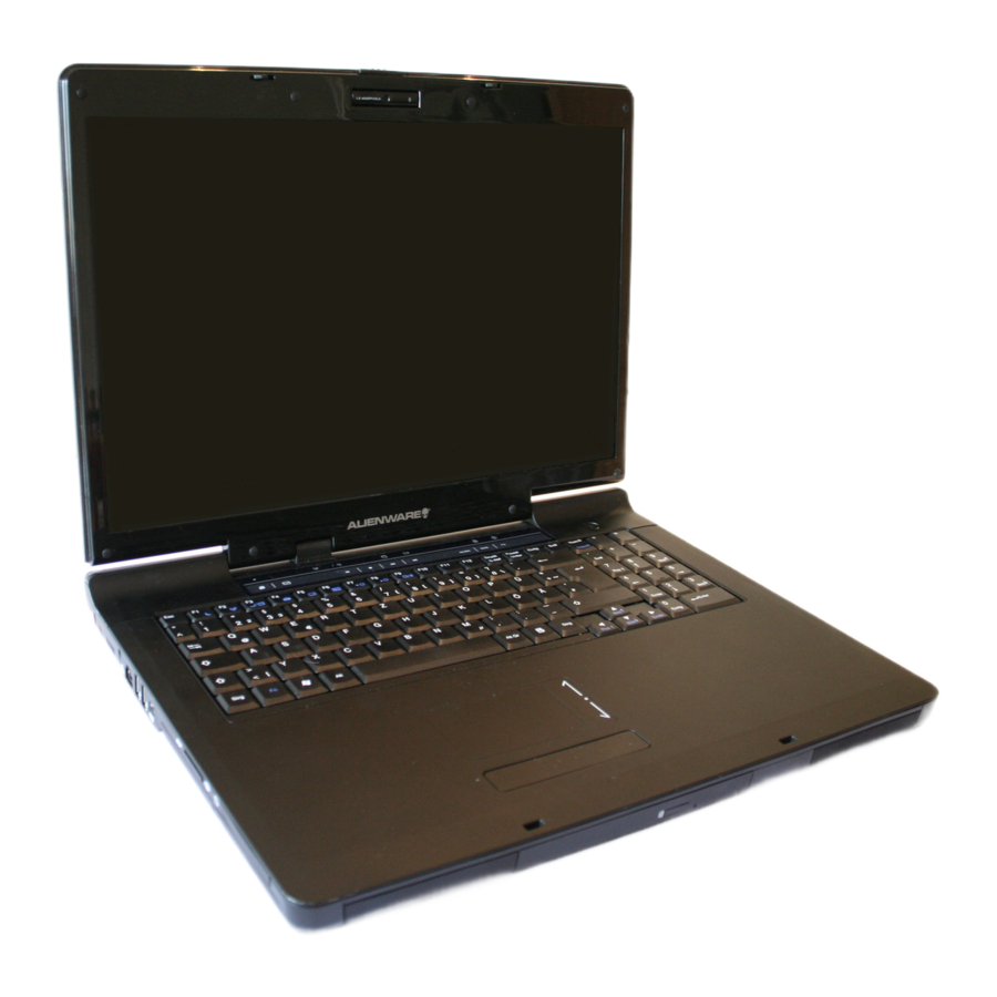
Examining Your Product
Before you start using your computer, you need to get acquainted with your notebook's main features and interfaces:

- Web Cam
- LCD Latch
- LCD Screen
- Power Button
- Keyboard
- Two Click Buttons
- Seven System LEDs
- Nine Finger-Touch Buttons
- Touch Pad
- ODD Drive
- Two Speakers
Note: Press this key combination (Fn+F4) to power on and power off the optional Web Cam module. After powering on the Web Cam, you need to activate its function through Windows.
Front View

- LCD Latch
- Two Speakers
- CIR Infrared Receiver Underneath
- Emergency Latch
- Eject Button
- ODD Drive
Rear View

- VGA Port
- S-Video Out Connector
- Ventilation Holes
- RJ11 Fax/Modem Connector
- Audio-In Connector
- TV-In Connector
- S-Video In Connector
- DC-In Jack
- USB Connector
- DVI Connector
- Ventilation Holes
Left View

- PCI Express Card Slot
- Media Card Slot
- Two USB Connectors
- Kensington Lock
- Ventilation Holes
- RJ 45 LAN Connector
- IEEE1394 Connector
- Two HDD Doors
Right View

- SPDIF-Out Connector
- Three Audio-Out Ports (Front/ Surround/ Center speakers)
- Microphone Jack
- Headphone Jack
- Digital Volume Dial
- Ventilation Holes
- USB Connector
Bottom View

- Compartment Door
- Ventilation Holes
- Two HDD Doors
- Woofer
- Battery Latch
- Battery Pack
Two Types of Audio Jack

The Two System LEDs
The two System LEDs are closely knitted together to reflect the system and battery recharge statuses as below.
 | Off |
|
| Blue |
| |
| Blue blinking once per 1.5 seconds |
| |
| Amber |
| |
| Purple |
| |
| Purple blinking once per second |
| |
 | Amber blinking once per 3 seconds |
|
| Amber blinking once per second |
| |
| Amber blinking five times per second |
|
Note: The two System LEDs are located at the rear bottom side of the LCD display screen.
For more details on Standby and Hibernate, please refer to Power Options in the Control Panel of your Microsoft Windows operating system.
The Seven Status LEDs
 | The Num Lock LED The LED will be lit when the keyboard is in Num Lock mode. In this mode, the embedded numeric keypads can be used. |
 | The Caps Lock LED The LED will be lit when the keyboard is in Caps Lock mode. In this mode, all characters you type are in uppercase. |
 | The Touch Pad LED The LED will be lit when the touch pad function is activated. You can press the (Fn+F5) key combination to switch off and to switch on the touch pad function. |
 | The HDD/ODD LED The LED will be lit when the system is accessing the hard disk drive and/or optical drive. |
 | The AC Adapter LED The LED will be lit when the system is connected to an AC adapter. |
 | The Wireless LED The LED will be lit when the wireless function is powered on. |
 | The Finger-Touch Button LED The LED will temporarily be lit when any of the finger-touch buttons is pressed. For details on finger-touch buttons, please refer to "The Nine Finger-Touch Buttons" Chapter. |
Note: The seven Status LEDs are located near the topside of the keyboard. For the exact location, please refer to the Panoramic View diagram in "Examining Your Product" Chapter.
The Power Button
Power Button
This Power Button is programmable by user. For details on how to program this button, please refer to Power Options in the Control Panel of Windows.

Note: The Power Button is located near the right side of the keyboard. For the exact location, please refer to the Panoramic View diagram in "Examining Your Product" Chapter.
The Nine Finger-Touch Buttons
 | TV Button (Optional) Press this button to run the TV Program. |
 | DVD Button (Optional) Press this button to run the DVD Program. |
 | Music Button (Optional) Press this button to run the Music Program. |
 | Next Track Button Press this button to skip to the next track/chapter of media playback. |
 | Previous Track Button Press this button to skip to the previous track/chapter of media playback. |
 | Stop Button Press this button to stop media playback. |
 | Play/Pause Button Press this button to play or pause media playback. |
 | Email Button Press this button to activate the email function. |
 | Internet Button Press this button to activate the Internet function. |
Note: The nine Finger-Touch Buttons are "finger-touch sensitive" and are located near the top of the keyboard. For the exact location, please refer to the Panoramic View diagram in "Examining Your Product" Chapter.
Note: The system supports Windows MCE and Windows XP operating systems. Windows MCE supports full media center features.
In order to take full advantage of the three buttons (TV Button, DVD Button, Music Button), you are requested to install the Function Key Controller program as supplied in the system driver CD. Without installing this program, you will not be able to activate these functions (through these three buttons) unless you have entered into the main menu of the media center software. By installing this program, you will be able to activate these functions (through these three buttons) whether you have entered into the main menu of the media center software or not.
PCI Express Card And Media Slots

Please observe the safety measures below:
When the PCI Express Card is not inserted into the PCI Express Card slot, make sure this slot is covered by the "PCI Express Card slot door" as supplied together with this notebook. The purpose of this "PCI Express Card slot door" is to prevent foreign matter from entering into the system unit through this slot when the PCI Express Card is not inserted. When inserting this "PCI Express Card slot door", please make sure the arrow is on the topside as shown above. Inserting this door upside down may cause damage to your notebook.
When no card (SD/MMC/MS Cards) is inserted into the media slot, make sure this slot is covered by the "media slot door" as supplied together with this notebook. The purpose of this "media slot door" is to prevent foreign matter from entering into the system unit through this slot, when no card is inserted. When inserting this "media slot door", please make sure the arrow is on the topside as shown above. Inserting this door upside down may cause damage to your notebook.
Operating Temperature
Operating Temperature: 10ºC to 35ºC.
The Fn Key
The <Fn> Function Key is located near the bottom-left corner of the keyboard. This key is used together with other keys to activate certain pre-defined functions. To activate these functions, press and hold down <Fn> together with the keys described below:
 | Sleep Switch Press this key combination (Fn+F1) to enter sleep mode. In sleep mode, the LCD display and selected devices will be switched off for less energy consumption. |
 | Wireless LAN Switch Press this key combination (Fn+F2) to power on and power off the Wireless LAN module. Powering on the Wireless LAN by pressing this key combination (Fn+F2) does not automatically activate the Wireless LAN function. After powering on, you need to activate the Wireless LAN function through Windows. The main purpose of this key combination (Fn+F2) is to provide you with a quick way to turn off the power of Wireless LAN when entering venues like airplanes, airports, and hospitals where the usage of Wireless LAN is prohibited or not advisable. |
 | LCD/CRT/TV Switch Press this key combination (Fn+F3) to switch between LCD only, CRT only, TV only, LCD/CRT simultaneously, and LCD/TV simultaneously. |
 | Web Cam Switch (Optional) Press this key combination (Fn+F4) to power on and power off the Web Cam module. After powering on the Web Cam, you need to activate its function through Windows. In addition, if you have Windows XP, you can also use Windows Movie Maker to create, edit and share video. |
 | Touch Pad Switch Press this key combination (Fn+F5) to switch off and to switch on the touch pad function. When the touch pad function is switched off, the touch pad device still can work temporarily for three to five seconds during system reboots into the Windows operating system, or resumes from standby or hibernation. |
 | Mute/Un-mute Switch Press this key combination (Fn+F6) to mute and to un-mute audio volume. |
 | Decreasing Brightness Press this key combination (Fn+F7) to decrease the brightness of the LCD display. |
 | Increasing Brightness Press this key combination (Fn+F8) to increase the brightness of the LCD display. |
 | Bluetooth Switch (Optional) Press this key combination (Fn+F9) to power on and power off the Bluetooth module. Powering on the Bluetooth by pressing this key combination (Fn+F9) does not automatically activate the Bluetooth function. After powering on, you need to activate the Bluetooth function through Windows. The main purpose of this key combination (Fn+F9) is to provide you with a quick way to turn off the power of Bluetooth when entering venues like airplanes, airports, and hospitals where the usage of Bluetooth is prohibited or not advisable. |
 | Alien Head LED On/Off Switch Press this key combination (FN+F10) to turn the Alien Head LED on and off. |
 | Touch Capacitance Disable Switch Press this key combination (Fn+F11) to disable the touch capacitive keys. |
Note: The proper way to activate Wireless LAN and Bluetooth is described below:
- Press this key combination (Fn+F2) to power on Wireless LAN.
- Press this key combination (Fn+F9) to power on Bluetooth.
- Activate the application programs in Windows.
The effective range of the Bluetooth system is 10 meters.
Note: Depending on the configuration of the notebook computer you have purchased, some of the function keys may have no function.
Battery
Battery Pack
Your notebook is equipped with a high-energy rechargeable Lithium Ion (Li-Ion) battery pack. Battery life will vary depending on the product configuration, product model, applications loaded on the product, power management settings of the product, and product features used by the customer. As with all batteries, the maximum capacity of this battery will decrease with time and usage.
Recharging The Battery Pack
Your notebook supports both on-line and off-line recharge. Follow the procedure below to recharge battery:
- Make sure the battery pack is installed in the notebook.
- Connect the AC adapter to the notebook and to an electrical outlet.
The two System LEDs are available to reflect the system status as well as the battery status. For details on the System LEDs, please refer to "The Two System LEDs" Chapter. When the notebook is OFF, a depleted Li-Ion battery will take three hours to recharge.
Battery Maintenance
To maintain the battery pack's maximum capacity, you should occasionally let the notebook deplete its battery power completely before recharging.
To carry out a complete depletion of the battery, disconnect the AC adapter and let your notebook consume the remaining battery power. To speed up the depletion, use the HDD as much as possible and set the LCD as bright as possible. When the battery is empty, wait for the notebook to cool down (especially the battery). The temperature should be within 15-25°C (59-77°F). Then insert the AC adapter to recharge the battery.
Power Consumption
Windows XP, the latest Windows operating system, has incorporated the latest state-of-the-art ACPI (Advanced Configuration Power Interface) power management methodology. In order to fully utilize the power of your battery packs, it would be a good idea for you to spend some time acquiring a basic understanding of the power management concept from your operating system.
In Windows Operating Systems, you can go through Power Options of the Control Panel according to the version of the Windows Operating System the notebook uses. We shall not describe them in detail. The Power Options in Windows XP are further divided into the categories below:
- Power Schemes
- Alarms
- Power Meter
- Advanced
- Hibernate
Windows Vista's Power Options include three preferred power plans to choose from:
- Balanced
- Power Saver
- High Performance
Reducing Power Consumption
Although your notebook (together with the operating system) is capable of power conservation, there are measures you can take to reduce the power consumption:
- Use the AC power whenever possible.
- Lower the intensity of the LCD backlight. A very bright screen translates to higher power usage.
- Try to use the HDD or the PCMCIA drive to read and write files, instead of using the external USB FDD.
Note: The battery pack should be locked in the battery compartment all the time.
Removing The Battery Pack
This battery pack can easily be removed and replaced. Make sure that the computer is properly shutdown before changing the battery pack. If you would like to change the battery pack while the power is on, make sure this battery pack is not the only electrical source to the system unit. Follow the steps below to remove the battery pack.

- Have the system properly shutdown.
- Flip the system upside down as shown.
- Push the battery latch to unlock the position as shown by #1.
- The battery pack will pop up as shown by #2.
- Remove the battery pack as shown by #3.
To insert the battery pack, reverse the steps above.
Questions and Answers
I can feel a mild heat next to the battery pack. Is this normal?
The battery will generate heat during recharging and discharging. There is a protection circuit inside the notebook to prevent overheating. You do not need to worry.
My battery operation time is not as long as it should be. Why?
The battery is heat sensitive and can only be charged to its maximum if the battery and its environmental temperature remain within 15-25°C (59-77°F). The more the temperature deviates from this range during recharging, the less chance there is for the battery to be fully charged. In order to recharge the pack to its full capacity, users are requested to cool down the unit by unplugging the AC Adapter. Wait until it is cooled down. Then plug in the AC Adapter to start recharging again.
I did not use my spare battery for a few days. Even though it was fully recharged, there wasn't as much power left as a newly charged one. Why?
The batteries will self-discharge (1% per day for Li-Ion) when they are not being recharged. To make sure a battery pack is fully charged, recharge before use. Always keep the battery inside the notebook and have the AC adapter connected whenever possible.
I did not use my spare battery for months. I am having a problem recharging it.
If you happen to leave your battery pack to go through an extended period of self-discharge, say more than three months, the battery voltage level will become too low and needs to be Pre-Charged (to bring the battery voltage level high enough) before it automatically (for Li-Ion only) resumes its normal Fast Charge. Pre-Charge may take 30 minutes. Fast Charge usually takes 2-3 hours.
Memory
Your notebook is equipped with a configurable memory unit. The industry standard JEDEC PC2700 (DDR2-333) S.O.DIMM memory module sockets are available for memory upgrade to 2048MB. The table below illustrates all the possible ways system memory can be configured.

| Total Memory | Socket#1 | Socket#2 |
| 256MB | 0MB | 256MB |
| 256MB | 256MB | 0MB |
| 512MB | 0MB | 512MB |
| 512MB | 256MB | 256MB |
| 512MB | 512MB | 0MB |
| 768MB | 256MB | 512MB |
| 768MB | 512MB | 256MB |
| 1024MB | 0MB | 1024MB |
| 1024MB | 512MB | 512MB |
| 1024MB | 1024MB | 0MB |
| 1280MB | 256MB | 1024MB |
| 1280MB | 1024MB | 256MB |
| 1536MB | 512MB | 1024MB |
| 1536MB | 1024MB | 512MB |
| 2048MB | 1024MB | 1024MB |
| 4GB | 2048MB | 2048MB |
Removing Memory Modules
Below is the procedure on how to remove the memory modules.

- Make sure the system is properly shutdown.
- Flip the system upside down as shown.
- Remove the battery pack as shown in the "Battery" Chapter.
- Remove the four screws as shown by #1.
- Remove the compartment door as shown by #2.

- Press the spring-locks sideways as shown by #1.
- The first memory module will pop up as shown by #2.
- Remove the first memory module as shown by #3.

- Press the spring-locks sideways as shown by #1.
- The second memory module will pop up as shown by #2.
- Remove the second memory module as shown by #3.
To insert the memory modules, reverse the steps above.
The HDD Drives
The Two HDD Sockets
Your notebook is equipped with two sets of HDD sockets. These sockets support industry standard 2.5"/9.5mm SATA-2 Gen1i (1.5Gb/s) hard disk drives. Unless you are going to install two Windows bootable HDD drives into these sockets, there is generally no need to distinguish which socket is the primary socket and vice versa. Below are the three major scenarios:

- One Windows bootable HDD drive: You are at your liberty to use either one of the two sockets. But the primary socket is your preferred choice for the bootable HDD drive.
- One Windows bootable HDD drive and another Windows non-bootable HDD drive: You are at your liberty to use either one of the two sockets for the bootable HDD drive. Again, the primary socket is your preferred choice for the bootable HDD drive.
- Both HDD drives are Windows bootable: Choose the HDD drive you want the system to boot up from and have this drive installed on the primary socket.
Removing The Hard Disk Drives
Use the procedure below to remove your system's the hard disk drives.

- Make sure the system is properly shutdown.
- Flip the system upside down as shown.
- Remove the battery pack as shown in the "Battery" Chapter.
- Remove the two screws as shown by #1.
- Remove the two HDD drives as shown by #2.

- Remove the four screws as shown by #1.
- Remove the HDD door as shown by #2.
To insert the HDD drives, reverse the steps above.
Safety Instructions

Please read these safety instructions carefully.
Please keep this User's Manual for future reference.
Please disconnect this equipment from the AC outlet before cleaning. DO NOT use liquid or sprayed detergent for cleaning. Use a clean moistened cloth.
The wall socket used should be positioned near the equipment and should be easily accessible.
Please keep this equipment free from humidity.
Place the equipment on a reliable surface at all times. A drop or fall can cause severe damage.

The openings of the enclosure are for air ventilation and are meant to protect the equipment from overheating. DO NOT COVER THE VENTILATION OPENINGS.
Verify the voltage of the power source before connecting the unit to any power outlet.
DO NOT step on or place anything over the power cord.
All cautions and warnings on the equipment should be noted.
If the equipment is not used for a long period of time, disconnect the equipment from the power source to avoid damage from power spikes.


NEVER pour any liquid into any openings; a fire or electrical shock is possible.
For safety reasons, other than pre-designated ports and doors, the equipment should be opened only through qualified service personnel.
If one of the following situations should arise, the equipment should be checked by an authorized technician:
- The power cord or plug is damaged.
- Liquid has penetrated into the equipment.
- The equipment has been exposed to excessive moisture.
- The equipment does not work well, or you fail to get it to work according to the user's manual.
- The equipment has been dropped or damaged.
- The equipment has obvious signs of breakage.
DO NOT LEAVE THE EQUIPMENT IN TEMPERATURES BELOW -20ºC(-4ºF) OR ABOVE 60ºC(140ºF). IT MAY CAUSE DAMAGE TO THE EQUIPMENT.
Never install modem/telephone wiring during a lightning storm.
Never install modem/telephone jacks in wet locations unless the jack is specially designed for wet locations.
Never touch un-insulated modem/telephone wires or terminals unless the modem/telephone line has been disconnected at the network interface.
Use caution when installing or modifying modem/telephone lines.
Avoid using a modem/telephone (other than a cordless type) during an electrical storm. There may be a remote risk of electric shock from lightning.
This computer contains an internal lithium battery-powered real-time circuit. There is a risk of explosion and injury if the battery is incorrectly replaced or handled. Do not attempt to recharge, disassemble, immerse in water, or dispose of it in fire. Replacement should be done through your notebook dealer.
THE CD-ROM/DVD-ROM IN THIS NOTEBOOK EMPLOYS A LASER SYSTEM.
- To ensure proper use of this product, please read the relevant instructions carefully and retain for future reference.
- Should the unit ever require maintenance, contact your local dealer.
- Use of controls, adjustments or the performance of procedures other than those specified may result in hazardous radiation exposure.
- To prevent direct exposure to the Laser Beam, do no try to open the enclosure.
The internal CD-ROM/DVD-ROM drive is classified as a CLASS 1 LASER PRODUCT. The label is located on the outside of the CD-ROM/DVD-ROM drive with the following wordings:
CLASS 1 LASER PRODUCT
KLASSE 1 LASER PRODUKT
There is a danger of explosion if the battery is incorrectly replaced. Replace only with the same or equivalent type recommended by the manufacturer. Dispose of used batteries according to the manufacturer's instructions.

Your notebook contains a Ni-MH or Li-Ion battery pack. There is a risk of fire and chemical burn if the battery pack is handled improperly. Do not disassemble, crush, puncture, short external contact, dispose of in water or fire, or expose it to temperatures higher than 60ºC.
Handle the battery pack very carefully. Avoid touching the metal leads on the connector of the battery case.
Use only the approved AC Adapter with your notebook. Using the wrong type of AC Adapter may cause serious damage to your notebook.
The AC Adapter can accept a line voltage ranging from 100V to 240V and is compatible with most international power sources. If you are unsure whether your power source is compatible, please contact the local dealer for assistance.
To reduce the risk of fire, use only a No. 26 AWG or larger telecommunication line cord.
For continued protection against the risk of fire, replace only with the same type and rating of fuse.
If the computer is not sold in the German area, please use only the local recognized power supply cords that are recommended by the manufacturer.
Don't expose your notebook to excessive heat or coldness (frost). Don't drop, spill fluids or open the exterior of the case. This can damage the notebook and void the warranty.
This notebook computer contains a certified optical module that is equivalent as a Class 1 LASER PRODUCT.
Documents / ResourcesDownload manual
Here you can download full pdf version of manual, it may contain additional safety instructions, warranty information, FCC rules, etc.
Advertisement


Need help?
Do you have a question about the Area-51 m9750 and is the answer not in the manual?
Questions and answers