Advertisement
- 1 COMPONENTS
- 2 INTRODUCTION
- 3 SAFETY
- 4 UNFOLDING THE BIKE
- 5 FOLDING THE BIKE
- 6 LOCKING BLOCK
- 7 USING THE BROMPTON T LINE
- 8 3-SPEED GEAR SHIFTER - RIGHT HAND SIDE
- 9 4-SPEED GEAR SHIFTER - LEFT HAND SIDE
- 10 BRAKES
- 11 LIGHTING
- 12 THE REAR FRAME CLIP
- 13 LUGGAGE
- 14 FRONT CARRIER BLOCK - T LINE
- 15 CLEANING & LUBRICATION
- 16 ADJUSTING THE SADDLE POSITION
- 17 SADDLE HEIGHT INSERT FITTING
- 18 BRAKE LEVER ADJUSTMENT
- 19 REAR WHEEL - REMOVAL AND REFITTING
- 20 REAR WHEEL - 12-SPEED REMOVAL AND REFITTING
- 21 FRONT WHEEL – REMOVAL AND REFITTING
- 22 ROUTINE REPLACEMENTS
- 23 Documents / Resources
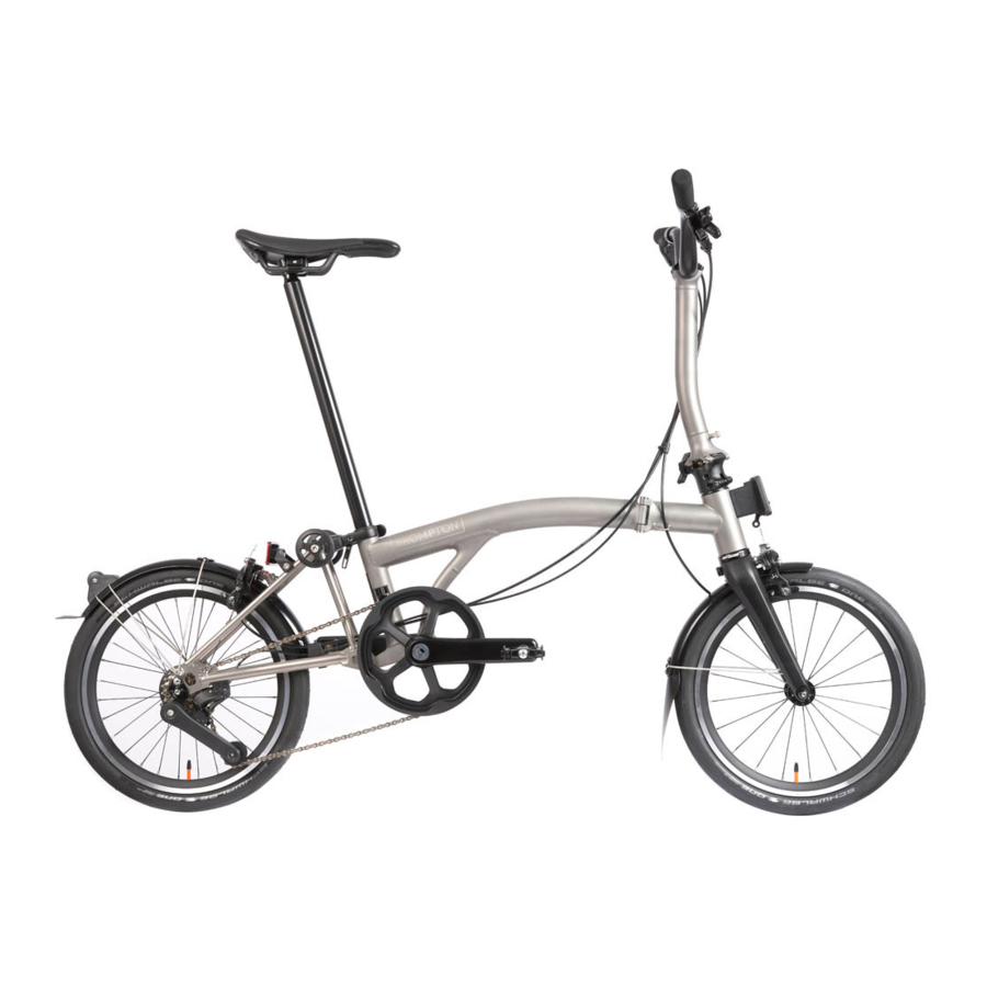
COMPONENTS

INTRODUCTION
Before using your Brompton T Line, please read this manual noting the sections on safety and folding in particular.
While this manual is intended as a guide, it is not a comprehensive guide to cycling or bicycle maintenance.
To activate your 7 year extended warranty you must register your bike in the My Brompton section of our website to record the details of your bike(s); that way, if your bike is stolen or we have any need to contact you, we will have a record to refer to. You will be asked to enter your serial and frame numbers: the serial number is located on a plate at the back of the main frame; the frame number is stamped on the main frame near the bottom bracket. The information remains on the Brompton database and will not be passed on to third parties https://www.brompton.com
If you carry out any adjustments or maintenance work yourself, please read the relevant sections of this manual first, as it's quite easy to get things wrong, and to impair the folding process or damage your bike. This manual contains some tips and advice for using your Brompton but if you are ever unsure of how to maintain your bike, visit an authorised Brompton dealer for expert advice. For a list of dealers, please visit our website: https://www.brompton.com/Find-a-Store
We recommend having your bike inspected and serviced by a Brompton dealer regularly.
CARRYING & WHEELING THE FOLDED BIKE
- Owners are responsible for assessing the way they use the bike at all times, and should ensure that they take due care of their safety and welfare when riding, moving or carrying their bike
- Brompton accept no responsibility for any injury caused when lifting and handling a folded bike
- A Brompton T Line bike weighs between 7 and 8kg, depending on the equipment fitted
- Luggage fitted to the front carrier block can also weigh up to 10kg
- Owners must take due consideration of the weight of their bike and any luggage they plan to lift or carry, and balance this against their particular physical capabilities; the circumstances i.e. route, under-foot conditions etc, must also be considered before each lift and/or carry of the bike and luggage
- Owners should always remove luggage from their folded bike so they do not attempt to lift or carry the combined weight of the bike and luggage
- Whenever you are no longer able to ride your Brompton, inside a train station for example, you should first push it as far as possible, then fold it up and roll it on the rear rollers before carrying it for the shortest distance
- It is recommended that the folded bike is carried one-handed, most comfortably with your arm straight and the bike to your side. The bike should be held either by the saddle, or the main frame below the saddle, whichever is most suitable for you
- If you have to carry the bike for any distance, then it may be appropriate to swap the bike between each hand at suitable intervals, depending on your capabilities
- Carrying the folded bike two-handed is only advisable over a very short distance, as it can only be done by holding the bike at chest/stomach level in order to avoid knocking your legs or knees against the bike; this requires both arms to be bent with an approx 90degree bend, which will place extra strain on your arms
The small rollers fitted as standard on a Brompton are useful for pushing the folded bike into tight spaces. Using the raised handlebar as a handle, the folded bike may also be pulled around on these rollers, though this only works on a smooth surface. Remember to raise the seatpost slightly from the fully-down position so that it does not hinder the bike from rolling along, but not so high that the bike unfolds (see locking block). You can also push the bike along by the saddle.
The folded bike is not designed to be used as a stool, do not sit on the bike when folded.
SAFETY
The Brompton T Line is designed for use on roads and well-made paths, carrying a maximum load not exceeding 110kg (rider and luggage weight included). A Brompton is not intended for stunts, off-road riding or extreme sports. Your Brompton should be used for its intended purpose.
Misuse may lead to failure of some components and void your Brompton warranty. We do not recommend fitting a child seat or trailer to the Brompton, doing so will invalidate the Brompton warranty.
Before riding your Brompton for the first time, and periodically thereafter, please pay close attention to the following:
- We recommend the use of an approved cycling helmet, even in countries where their use is not mandatory
- Read and follow the national legal requirements of the country where you are riding, and comply with all applicable traffic laws
- Make sure the wheel rims are clean and undamaged along the braking surface, and check for excess rim wear. If you doubt the safety of your rims, have them inspected by an authorised Brompton dealer
![]()
- Check brakes, tyres and steering regularly
- Keep brakes and gears properly adjusted and operating cables in good condition
- In rain, the brakes may be less effective and roads more slippery so brake sooner
- Check that all wheel fixings are properly tightened (see torque table)
- In the UK, the left hand brake lever operates the rear brake and the right hand lever operates the front brake, but this varies from country to country
- When riding in the dark, wear reflective clothing and use lights (front and rear); check to ensure that your lights comply with local laws

Before or after each ride, pay close attention to the following:
- Ensure that the quick release seatpost clamp is secured and the saddle is at the correct height
- That the hinge clamps are in place, with levers firmly tightened
- During folding and unfolding, as well as during use and maintenance, avoid putting your hands or fingers anywhere they may be caught or trapped
- Ensure the bike is correctly folded or unfolded to avoid possible injury
- Never try to alter the height of the handlebar stem where it connects to the front forks

Many components on a bike are highly stressed, and with high mileage, heavy loads or hard riding, will eventually reach the end of their design life; in particular, aluminium alloy has a limited fatigue life. Failure in use can cause injury. You should regularly check all load-bearing parts for any signs of damage, discolouration corrosion, or cracking, and replace if necessary. Please visit an authorised Brompton dealer for expert advice if you are uncertain.
The bike must not be subject to any modification, repair or replacement other than as authorised by Brompton Bicycle Ltd. The bike must be serviced by an authorised Brompton Dealer.
If the bike has been subject to a crash or impact you should stop using the bike immediately and have the bike inspected by a Brompton dealer. Damaged components should be replaced before the bike is ridden again. Any deep scratches or gouges in the frame or components can severely weaken the part and cause premature failure.
Carbon components (fork, handlebar, crank arms) should be inspected for any signs of wear, scratches, impacts or discolouration that could indicate the part is damaged. If the parts show signs of damage you should stop riding the bike imediately and have it inspected by an authorised Brompton dealer. It is vital that you adhere to the correct tightening torque for all components that interface with a carbon component; overtightening can damage the carbon part and cause sudden premature failure. Undertightening the part might result in components moving in use which could cause you to lose control of the bike when riding.
Note: We recommend that genuine Brompton parts are used for safety-critical components.
UNFOLDING THE BIKE
- Remove pedal
Stand on the left (non-driveside) of the bike. Remove the detachable pedal from the pedal holder in the rear of the fork. The pedal holder can be covered with the rubber cover to avoid it being clogged with debris.

- Insert pedal
Insert the detachable pedal into the quick release pedal mount by pushing the hex shaped axle of the detachable pedal into the mount, whilst twisting to align the axle to the inside of the mount. Apply pressure until there is a click to indicate that it is fully inserted.

- Unfold handlebar
To release the handlebar, firmly push down on the end of the grip nearest to you with your left hand. Swing the handlebar up until the hinge closes. - Tighten hinge
Once the hinge is closed, the black clamp lever can be closed firmly.

- Raise saddle
Undo the seat clamp lever, pull the seatpost up and re-clamp to secure the seatpost.

- Lift to unhook
Place your right hand on the saddle and hold the handlebar stem with your left hand, near the hinge.
Look down where the chain runs between the two wheels and you will see the black hook holding the front wheel to the rear frame.
Lift the handlebar stem with your left hand, to lift the hook above the tube it is resting on.

- Unfold front wheel
Swing your left hand away from you in an arc to push the fork and front wheel away from you, push until the hinge on the main frame is closed.
When doing this ensure that the front wheel remain pointed in a forward direction, the hook must also remain on your side of the bike.
At the end of this step, the front wheel should be pointing forward at a slight angle, not parallel with the rear wheel. - Tighten hinge
The hinge on the main frame should now be closed by tightening the black clamp lever firmly.
The bike is now in its "parked" position – it will stand by itself on level ground.

- Unfold rear wheel
To complete the unfold, hold the handlebar with your left hand, and with your right hand lift the rear of the bike up swiftly by the saddle and swing the rear wheel backwards into position.

- Unfolded
Push down on the saddle to ensure the suspension block pushes against the mainframe; there should be a audible click as it locks into place.
![]()


FOLDING THE BIKE
- Spin cranks
Stand on the left (nondriveside) of the bike. Spin the cranks so the right-hand pedal is pointing towards the back of the bike.

- Fold rear wheel
Turn the handlebar slightly to the left so it is not parallel with the rear wheel. There is a lever directly below the seat clamp. Press it forward, then lift the rear of the bike swiftly allowing the rear wheel to swing under the main frame.

The bike should now be in the "parked" position – it will stand by itself on level ground. - Undo hinge
Undo the hinge clamp lever in preparation for the next step.

- Fold front frame
With your left hand, hold the handlebar stem below the handlebar. Swing the front wheel away and to the right, bring the handlebar stem round in a clockwise stirring motion. When doing this, make sure to keep the front wheel pointing in the forward direction, the hook must remain on your side of the bike.
Do this until the front wheel is alongside the rear wheel, and the hook located on the front fork can hook on the rear frame. You may need to slightly lift the front of the bike.

- Lower hook
Lower the hook over the chain stay located on the rear frame.

- Undo hinge
Undo the hinge clamp lever on the handlebar stem by 4-6 turns.

- Fold handlebar
Let the handlebar stem fall down. The nipple will secure it in place.
![]()
- Lower saddle
Undo the seatclamp and lower the saddle fully. This locks the bike together, so it won't open up when carrying. Close the seat clamp lever once saddle is lowered.

- Remove pedal
To remove the detachable pedal, squeeze both buttons on the quick release pedal mount, while puling the pedal outwards. - Insert pedal
Remove the rubber cover from the pedal holder on the rear of the front fork. Place the detachable pedal in the pedal holder, twist slowly when inserting to correctly line up the hex shaped axle to the inside of the holder.

The bike is now folded and ready to be picked up and carried.
![]()


LOCKING BLOCK
ADJUSTMENT
When you pick up the folded bike, the bike cannot unfold because the locking block LB contacts the seatpost SP to stop the rear frame from moving. The LB can be adjusted to obtain the correct gap between itself and the SP. If the gap is too small the post will catch on it when folding the bike, too large and the folded bike may partially unfold when picked up.
It is easiest to make adjustments to the LB with the bike fully folded with the seatpost raised. When the seatpost is raised, make sure it is locked in place using the seat clamp.
To decrease the gap between the LB and the SP (fig. 1), using a 4mm hex key, unscrew the cap head socket screw inside the LB half a turn at a time and then lower the seatpost to check if it has clearance. If the gap is still too wide, unscrew another half turn, and check the seat post again. Repeat this process until the correct size gap is obtained.

PUSHING/PULLING THE BIKE WHILST FOLDED
The bike can be pushed/pulled whilst folded, as an alternative to picking up and carrying the bike. In the folded position, raise the saddle until the bottom of the seatpost comes into contact with the locking block (fig. 2). Because the locking block still contacts the seatpost, the bike is still secured in the folding position, but with the saddle slightly raised. The raised saddle can be used as a handle to push/pull the bike.

USING THE BROMPTON T LINE
TYRE PRESSURES
Tyre pressure is important for both comfort and safety. Please note the following tips for ensuring a safe and comfortable ride.
It is important to keep your tyres well-inflated; soft tyres increase pedalling effort (which takes the fun out of riding), wears tyres down quickly and has an adverse effect on handling. Keeping your tyres well-inflated is highly recommended.
The most appropriate pressure depends on your weight and preference. It's also worth remembering that a very hard tyre isn't always faster. A hard tyre might be faster in the velodrome, on a rough road a lower pressure will deflect more easily over uneven and rough road surfaces and therefore roll faster and make the ride more comfortable. Generally a slightly lower pressure in the front wheel and slightly higher in the rear is recommended, this accounts for the different weight distributions between the two tyres.
Brompton T Line bikes are fitted with Presta valves (fig. 3) which differ from the Schrader valves used on a standard Brompton.
Your pump may need reconfiguring to work with the Presta valve, please refer to the pump manufacturers instructions on how to do this.

The table below shows recommended tyre pressures for tyres supplied on Brompton T Line bicycles.
| SCHWALBE ONE | SCHWALBE MARATHON | MARATHON RACER | ||||
| MIN(psi) | MAX(psi) | MIN(psi) | MAX(psi) | MIN(psi) | MAX(psi) | |
| FRONT | 65 | 100 | 65 | 110 | 65 | 110 |
| REAR | 65 | 100 | 65 | 110 | 65 | 110 |
TORQUE VALUES
A list of torque values for the major components is shown here.
These parts should be checked periodically, as well as during routine maintenance and repair of the bicycle.
| Part name | Torque (Nm) |
| Bottom Bracket Cups | 40-50 |
| Crank Arm Bolt | 38-41 |
| Chain Tensioner Hanger Nut | 5 |
| Left Hand QR Pedal Mount | 11.8 |
| Right Hand Pedal | 20 |
| Derailleur Mounting Screw | 2 |
| Front Brake Nut / Pedal Mount | 8 |
| Rear Brake Nut | 8 |
| Mudguard Stay Fixings | 2 |
| Headset Preload Bolt | 4 |
| Steerer Hinge Clamp Bolts | 7 |
| Front Wheel Fixings | 7 |
| Rear Wheel Fixings | 7 |
| Pentaclip | 15 |
| Front Carrier Block Mounting Screws | 4.5* |
| Handlebar Clamp Screws | 3** |
| Hinge Spindle Nut (MF & HB) | 2* |
| Rear Hinge Bolt | 10* |
*Any fastener with an "*" should be replaced if removed at any point due to the presence of a non-reusable patch-lock present on the bolt during assembly. All replacement fasteners should be sourced from Brompton Bicycles to ensure safety.
**Ensure grease is present on the threads, and the washer is present under the head of the bolt before re-installing the handlebars if removed. If you do not have washers, please contact Brompton Bicycles for replacements. See Brompton Academy for installation video.
3-SPEED GEAR SHIFTER - RIGHT HAND SIDE
USING THE SHIFTERS
The 3-speed shifter uses a self-returning lever to change between the three gears. Pushing it down with your thumb will shift into an easier gear and flicking the lever upwards with the back of the thumb will shift into a harder gear (fig.1, 2). It is important to stop pedalling or back pedal when changing gear, if you do not do this, it is possible to damage the hub internals. The indicator window (fig. 2) shows you which gear is selected.

FITTING THE SHIFTERS
The shifter mounts to the right hand brake lever, it is held in place by two M3 screws, these should be tightened to 0.35Nm. Do not overtighten the screws as this can reduce the performance of the shifter and damage the parts.
As standard, a spacer (fig. 3) is fitted between the shifter and brake lever. This spacer is vital to ensure clearance between the shift lever and the grip.
On the M, H & S-type bikes using non-standard grips, the locking collar or grip material can interfere with the lever operation, if the spacer is not fitted.

FITTING A NEW CABLE
- Select gear 1 and then press the shift lever downward so it does not obscure the cable entry hole

- Feed the gear cable into the shifter and through the cable bush
- If there is resistance pushing the cable through the bush, pull the cable back a little and try again
- Once you can feel the cable pass through the bush keep feeding it until you feel slight resistance
- Keep feeding it through so that it follows around the guide inside the shifter and exits through the cable barrel

DO NOT FORCE THE CABLE AS THIS MAY DAMAGE THE SHIFTER
REFITTING THE GEAR CABLE
- Thread the inner cable through the cable housing
- Route the assembled cable correctly to the rear of the bike
- Thread the inner cable around the cable pulley

- Thread the cable through the clamp on the cable anchor and pull through before tightening the clamp nut
- Screw the indicator chain into the gear cable anchor

HUB-GEAR ADJUSTMENT
Adjustment must be carried out with the bike fully unfolded and with the indicator rod screwed into the hub. This should be backed off no more than half a turn to align with the cable.
The aim is to make sure that the indicator rod and chain move to the correct position in response to moving the trigger.
For this the cable has to be running free of kinks or sharp bends, with the cable pulley rolling freely.
While setting gears, keep the wheel spinning forwards, and pedal back and forwards, to ensure the gear engages. It's easiest, when altering the setting, to have the cable slack: select top gear and back and forward pedal.
Adjustment is carried out by slackening the lock nut, turning the cable anchor barrel (fig. 5) to obtain correct setting, and relocking the nut.
The indicator chain is correctly adjusted (fig. 6) when the shoulder S on the indicator rod IR is proud of the axle end by no more than 1mm (this can be seen by looking through the hole in the chain tensioner nut CTN) when in the middle position on the shifter is selected.
REMOVING THE GEAR CABLE

- Select gear 3 on the shifter, backpedal to engage the hub
- Unscrew the indicator chain locknut (fig. 5)
- Unscrew the indicator chain from the gear cable anchor
- Undo the gear cable anchor clamp nut and release the inner gear cable
- If there is a cable crimp fitted to the cable end you will need to remove this, then pull the cable out of the clamp
- Pull the cable housing away from the shifter
- Remove the inner cable from the cable housing
- Select gear 1 and then press the shift lever downward so it does not obscure the cable entry hole
- Feed the gear cable through the shifter so that the cable nipple ejects from the cable entry hole
- If there is resistance pushing the cable through the bush pull the cable back a little and try again
- Keep feeding the cable through until the cable can be fully removed from the shifter
4-SPEED GEAR SHIFTER - LEFT HAND SIDE
USING THE SHIFTER
The 4-speed shifter uses a self-returning lever to change between the four gears. Pushing it down with your thumb will shift into an easier gear and flicking the lever upwards will shift into a harder gear (fig.7). It is advised that each individual gear is changed while pedalling for smoother shifting or to avoid damaging the relating components. The indicator window will give an indication of which gear is selected (fig. 7,8).

FITTING THE SHIFTERS
The shifter mounts to the right hand brake lever, it is held in place by two M3 screws, these should be tightened to 0.35Nm. Do not overtighten the screws as this can reduce the performance of the shifter and damage the parts.
As standard a spacer (fig. 9) is fitted between the shifter and brake lever. This spacer is vital to ensure clearance between the shift lever and the grip.
On the M, H & S-type bikes using non-standard grips, the locking collar or grip material can interfere with the lever operation, if the spacer is not fitted.

FITTING A NEW CABLE

- Screw the barrel adjuster fully clockwise so that it is at its shortest setting, then unscrew by 2 turns
- Select the lowest gear (1) and then press the shift lever downward so it does not obscure the cable entry hole
- Feed the gear cable into the shifter in a slightly downward direction and through the cable bush
- If there is resistance pushing the cable through the bush pull the cable back a little and try again
- Once you can feel the cable pass through the bush keep feeding it until you feel slight resistance
- Keep feeding it through so that it follows around the guide inside the shifter and exits through the barrel adjuster.
DO NOT FORCE THE CABLE AS THIS MAY DAMAGE THE SHIFTER
SETTING THE GEARS
- Insert the inner cable IC into the cable housing CH

- Thread it all the way through until it exits through the end of the housing
- Route the cable along the bike frame following the same paths as the existing cables. This is essentail for folding
- When the cable reaches the rear frame, route the cable through the stopping block SB

- Using some needle nose pliers or similar, pull the cable through the housing and insert into the derailleur (fig.12)
- Tighten the bolt RS that holds the cable in place on the inside of the derrailleur

- Use the barrel adjuster on the shifter to make adjustments to the cable tension as needed (fig. 10)
- Unscrewing the adjuster will add more tension to the cable and improve shifting into the lower gear
- Screwing the adjuster inwards will reduce tension and improve shifting into the high gear (See gear adjustment information below)
- The jockey wheel on the derailluer needs to be in-line with the selected gear sprocket on the cassette


ADJUSTMENT
If the gears become louder than normal or start to skip and this is not due to dirt and grime on the parts, it could be due to cable stretch. This is especially common for new bikes or where new cables have been fitted. This can be fixed by adding tension to the cable, See cable tension instruction below. The derailleur not being aligned properly could also cause the same issue though this usually affects the highest and the lowest gear. In which case you will need to adjust the two limit screws LS on the outside of the derailleur. See limit screws instruction below.
LIMIT SCREWS - The limit screws LS operates in the same way they would on the traditional gearing system. These are used to set the limits on how far inwards or outwards the derailluer can carry the chain. If there is an issue with reaching the highest or the lowest gear, the limit screw may need adjusting. 2mm hex key is needed for adjusting.
LS-1 is used to create alignment on the largest sprocket on the cassete.
LS-2 for the smallest.

CABLE TENSION
To add tension lost due to cable stretch, place the bike in a stand. Unscrew the barrel adjuster (fig. 7) outwards a quater turn at a time, each time pedalling the bike whilst listening for the reduction of noise. A visual check can also be done to insure that the jocky wheel on the derailluer is aligned with the selected sprocket on the cassette. If the bike is failing to reach the largest sprocket this means that too much tension have been added screw the barrel adjuster inwards to remedy this issue (fig. 10).
MAINTAINANCE
It is vital that the key functional components like the chain, cassette and derailleur are kept clean and chain lubricated. These components should be checked periodically for damage and replaced whenever necessary. If these components are kept clean their lifespan will be extended and they will function better. If there is a build up of grease and dirt on the drivetrain, the gearing may not work properly.
BRAKES
You should adjust your brakes on a regular basis as they are critical to your safety. The time between adjustments will vary depending on how often you use your Brompton; if your brake lever touches the handle bar when you pull on it, your brakes need urgent adjustment. The brakes should be set so that the brake pads are as close to the rims as possible without interfering with the rotation of the wheels. Adjustment is carried out using the threaded cable stop on the brake lever. If you are unsure of how to do this, have it adjusted by a Brompton dealer or qualified bicycle technician.
- When setting the rear brake, the bicycle should be unfolded
- When setting the front brake, do not set the pads so close that they bind on the rim when the wheel is turned to the right or left
- Replace your brake pads if the grooves on the brake pad surface are less than 1mm deep
Keeping your rims and brake pads clean will improve your braking performance and increase the lifespan of the pads and rims. The black residue that accumulates on the rims is a mixture of dirt, pad material and aluminium powder worn from the braking surface of the rim, this residue is abrasive and will accelerate the wear of the rim and pads. When cleaning the pads and rims check to ensure they are not worn out and a worn rim or pads should be replaced immediately.
LIGHTING
Two options are available on Brompton T Line; a battery-operated front and rear lamp or a bike without lights. Please use lights in accordance with local laws. For technical information relating to the operation of the battery lamps please refer to the instruction sheets provided with the lights or to the technical section on our website https://www.brompton.com
THE REAR FRAME CLIP
To release the rear frame press the small lever (fig. 12) forward and lift the bike so the suspension block moves away from the latch and the rear wheel swings under the frame. Lower the bike so it sits in the parked position.

LUGGAGE
Brompton has a selection of luggage accessories that you may fit to your T Line Brompton. They have a load capacity of up to 10kg. Please pay attention to the instructions that come with all luggage before use. Using incorrect luggage may interfere with steering and could be dangerous.
Note: All Brompton front luggage is suitable for use on the T Line bike.
FRONT CARRIER BLOCK - T LINE
- Check that you have all the parts shown

- If fitting for the first time, remove the two fixing screws in the mounting holes M on the front of the headtube
- It is vital that you do not omit either of the serrated washers SW when fitting the retaining plate RP and that the correct torque is used on the screws STS
- The blue patches on the screws are there to lock them in place; do not tamper with, remove or expose this patch to moisture as the locking action will be greatly reduced
- The screws should not be re-fitted after the initial instillation; the blue patch will not function correctly.

FITTING INSTRUCTIONS
- You need a 4mm hex-key and a Posidriv screw-driver. Assemble the retaining plate RP and one of the bolts B, together with its serrated washer SW into the front of the carrier block body FCB followed by the spacer S
- Attach this to the head tube on the bicycle; orientate correctly (fig. 13)
- Insert the first bolt by two to three turns, do not tighten fully
- Insert the second bolt with serrated-washer, tighten by two to three turns
- Finally tighten both bolts firmly to a Torque of 4.5Nm
- Feed the bottom end of the latch lever LL through the hole in the base of the FCB and then, holding the bottom of the LL, position the top of the LL inside the FCB
- Feed the self-tapping screw STS through the hole in the LL and tighten.
The maximum load of the front carrier block is 10kg. Do not exceed the maximum load for the front luggage or modify the front carrier block or front luggage frame. Ensure that when carrying luggage you do not exceed the maximum load for the bicycle (including luggage and rider) of 110Kg. The fixings of the front carrier block should be checked regularly. The front carrier block is not suitable for mounting of a child seat. Do not attempt to carry luggage anywhere else on the bicycle. The bike is not designed to pull a trailer.
When the luggage carriers are loaded, the bicycle may behave differently, steering and braking may be affected. Luggage should be loaded evenly.
Before riding ensure that the front bag and front carrier block are secure and there are no loose straps or items of luggage that could get caught in the wheels of the bicycle.
Ensure that any luggage fitted does not obscure the reflectors and any lighting fitted to the bike.
This luggage carrier is only compatible with a Brompton bicycle and Brompton luggage & luggage frames. This luggage carrier is not compatible with a Brompton Electric bicycle or Brompton Electric luggage. Only luggage carriers and luggage manufactured or distributed by Brompton Bicycle Ltd should be used with the Brompton bike.
CLEANING & LUBRICATION
It is important to lubricate components to keep them running safely and efficiently. We recommend you do this regularly, though some parts will need more frequent lubrication.
The chain has to be well-lubricated for smooth pedalling. Apply chain lubricant while turning the pedals backwards, making sure it flows onto the rollers; allow the oil to work in by continuing to turn the pedals backwards, then wipe off any excess.
Take care not to get any lubricant on the brakes or wheel rims.
When lubricating the chain its worth remembering that you are trying to lubricate the chain rollers and not the plates, any lubricant on the plates isn't going to aid drivetrain efficiency and will simply serve to attract dirt. The best method is to carefully apply one drop of lubricant to each roller, this will take a little longer than just squirting lube on the chain while you back pedal, but will ensure the lube gets where it's needed and nowhere else.
The thread of the hinge clamp bolt and its washer should be greased occasionally. A thin smear of grease on the inside faces of the clamp plates also help them release more easily.
The gears and bearings are sealed; greasing need only be carried out during a major service by a bicycle mechanic.
When lubricating your Brompton, avoid getting oil or grease on the seatpost or the wheel rims.
Any good quality general purpose grease is satisfactory. For the chain, 'dry' chain lubricants with good penetrating properties give the best results. Consider the environmental impact of the lubricants and greases you use.
We advise using a bucket of hot soapy water and a sponge to clean the bike. Do not use a hose or pressure washer as this can force water into bearings and moving parts, driving out lubricant and causing corrosion.
ADJUSTING THE SADDLE POSITION
The angle and fore-aft position of the saddle can both be adjusted. To establish the most comfortable position you should start by adjusting the saddle into a neutral position; you can then work from there to find the best position. First loosen the Pentaclip bolt using a 5mm hex key until the saddle can be moved with little force. Be careful not to loosen this bolt too much as this will make adjustment more difficult.
Move the saddle rails in the clamp so that they are roughly centred (half way between maximum fore and aft position). Adjust the saddle into a level position, so that the top surface of the saddle is roughly level between the front and rear edge (fig. 14). Once the saddle is in a neutral position, tighten the Pentaclip bolt to 10Nm. Test the saddle position, you can adjust it to make it more comfortable.

ANGLE
If the nose feels like its pointing up, or feels as though the back of the saddle isn't giving enough support, you can angle the saddle forward. The saddle could conversely feel like it needs tilting back a little, to give more support from the nose, or if it feels like all the riders weight is resting on the back of the saddle. Once you have adjusted the saddle, tighten the Pentaclip bolt and spend some time riding, readjusting if necessary.
FORE-AFT POSITION
Moving the saddle back and forth from the neutral middle position will not only affect the reach (to the handlebar) but also the position relative to the pedals. By moving the saddle back you will increase the reach to the bars and make the bike a little more stretched out. Moving the saddle forward will make the bike feel shorter and more upright. Test the bike and readjust if necessary, making sure you securely tighten the Pentaclip to 10Nm.
ADDITIONAL SADDLE HEIGHT
If you can't gain enough height by re-positioning the saddle, there are two Brompton options which give more height: a telescopic seat pillar and a longer pillar extended by 60mm. The telescopic pillar can accommodate the needs of taller riders, with little change to the folded size.
The handlebars and control levers on the Brompton are factory-set to provide a compromise between compactness and riding comfort. Should you choose to make any changes, the folded handlebar or stem cannot lie as close to the front wheel as normal and increases the folded package.
If the handlebar stem assembly has to be moved for any reason, it is highly recommended that any adjustments are made by an authorised Brompton dealer or certified bicycle technician. The clamp bolt should be tightened to a torque of 10Nm.
SADDLE HEIGHT INSERT FITTING
Once you have the correct saddle position you can fit the saddle height insert. This should be fitted in cases where the saddle height is too high at maximum extension. The saddle height insert will allow you to set the saddle at the correct height each time the bike is unfolded.
SETTING THE SADDLE HEIGHT
- Remember to use your usual cycling shoes at this stage
- Adjust the saddle height so that when the pedal is at the bottom of the stroke and the heel of the shoe is on the pedal, your leg is straight

- When pedalling with the front of the foot, your leg will be slightly bent at maximum extension
- Once you are happy with the saddle height, mark the seatpost with a marker pen or tape at the top of the seat-slide tube

- The minimum height of the seatpost is reached when the seatpost extends out of the seat tube, below the bottom of the frame; the bike should not be ridden with the seatpost protruding from the bottom of the seat tube
- If you are unsure about the fitting process, your Brompton dealer will be able to assist you


FITTING THE INSERT
MEASURING AND CUTTING THE INSERT
- Raise the seatpost to maximum height
- Place the insert upside down against the post at the top of the seat-slide tube as shown (fig. 17) and mark the groove in the insert, closest to the mark on the seatpost

- Carefully cut the insert along this groove with scissors
![]()
- Mark the Pentaclip to show the saddle angle and position on the Pentaclip using a marker pen or tape
- Loosen the Pentaclip with a 5mm hex key and remove the saddle and O-rings from the top of the seatpost
- Remove the seatpost by sliding it out from the underside of the frame
- Squeeze the saddle height insert and insert it into the top of the seat-tube, aligning the key with the slot

- Engage the key with the base of the slot (fig. 19)
- Refit the seatpost into the underside of the frame (fig. 19), making sure the post is clean
- Refit the O-rings and saddle, align the setting marks on the Pentaclip and tighten (10Nm)
- Check the saddle height is correct at full extension, small adjustments can be made by moving the Pentaclip position up or down slightly on the post (fig. 14), for more information see https://www.brompton.com


BRAKE LEVER ADJUSTMENT
In order to achieve a comfortable and safe brake lever position, it is important to spend some time ensuring the lever is correctly adjusted. Depending on your hand size, you can adjust the distance of the lever from the bar; the lever can be set to be operated by one, two or three fingers.
The left and right hand levers are specifically designed for their respective positions; the lever is fitted with the clamp bolt facing upwards.

- LEVER ANGLE
The range of lever angle adjustment is restricted by the cable exit path, if the lever is angled too high it will cause problems for the operation of the brakes and in folding the bike.
When the bike is folded, the right hand brake cable housing will contact the fork leg. The lever angle should be set so that the cable housing lightly contacts the fork leg; too much contact will bend and damage the housing. For this reason, the lever blade features a kink allowing the lever blade to sit higher than the lever body, this offers a more comfortable position without affecting the cable housing path. - LEVER POSITION
The position of the lever on the bar can be adjusted to move the lever closer or further from the end of the handlebar grip. This adjustment will allow the lever to be positioned for one, two or three finger braking.
Positioning the lever for one finger braking will give a more secure grip on the bar but allow you to apply less braking force. Three finger braking will allow you to apply maximum braking force but reduce bar grip. - REACH ADJUSTER
Lever reach adjustment is controlled by the grub screw on the side of the lever body.
Screwing the reach adjuster into the lever body (2.5mm hex key) will bring the lever closer to the handlebar.
When the lever reach is adjusted closer to the handlebar it will cause the brake pads to move closer to the wheel rim. It may be necessary to adjust the lever bite point (engagement position) in order to give sufficient pad clearance; this can be achieved by screwing the barrel adjuster into the lever body.
If there is not enough adjustment at the barrel adjuster to give sufficient pad clearance and a satisfactory lever bite point, you may need to loosen the cable clamp bolt (10mm spanner) at the brake caliper to allow some cable to be pulled through. Be sure to re-tighten this bolt to 8Nm and ensure the cable is properly secured before using the bike. - BITE-POINT ADJUSTMENT
Lever bite-point (engagement position) adjustment is controlled by the barrel adjuster. Screwing the barrel adjuster into the lever body will bring the lever bite-point closer to the handlebar. Screwing the barrel adjuster outward from the lever body will move the bite point further from the handlebar.
The barrel adjuster uses a lock ring to secure it in position; this should be loosened before adjustment and tightened once the barrel adjuster is correctly positioned. - SECURING THE LEVER
Once the lever has been correctly positioned on the bar, the clamp bolt should be tightened to a torque of 2Nm (4mm hex key).
Correct cable routing and cable housing length is essential; cables must pass in front of the handlebar, to the left of the handlebar support and to the right of the main frame tube.
IF YOU ARE UNSURE ABOUT ANY OF THESE ADJUSTMENTS CONSULT YOUR BROMPTON DEALER, DO NOT ATTEMPT TO USE THE BIKE WITH POORLY ADJUSTED BRAKES
REAR WHEEL - REMOVAL AND REFITTING
- When fitting or removing the rear wheel, change the gear to the small sprocket on the cassette
- The chain tensioner should be disengaged from the chain before removing the wheel
- When fitted, ensure the wheel is seated correctly in the dropout, if not the gears may not function properly
- It is vital that you follow the correct fitting procedure and tighten all fixings correctly
REMOVAL
To remove the rear wheel, place the bike in a stand. In preparartion, the tension has to be removed from the chain. Acheive this by disengaging the CT. Once the chain is slack, it can now be removed from the C, and out of the way for the wheel to be taken off. Use a 5mm hex key to loosen the WS. Once loosened, to avoid the skewer nut SN spinning on the oppposite side, hold it in place. Then completely remove the WS. For the wheel to pass the brake caliper, the tyre has to be deflated. The wheel can now be guilded out with little pressure.
FITTING
When fitting the rear wheel, place the bike in a stand. Ensure that the correct running orientation by checking that the arrow on the tire wall is indicating a forward running orientation. Guide the wheel in place ensuring that the chain can be correctly seated on the cassette C later. Once the wheel is seated in place. Insert the skewer WS as shown (fig. 21). Tighten the skewer bolt to 7Nm. The chain tensioner CT can now be engaged by the chain.

REAR WHEEL - 12-SPEED REMOVAL AND REFITTING
- When fitting or removing the rear wheel, change the gear to the small sprocket on the cassette
- The chain tensioner should be disengaged when removing the rear wheel
- Ensure the wheel is seated correctly in the dropout, if not the gears may not function properly
- It is vital that you follow the correct fitting procedure and tighten all fixings correctly
REMOVAL
To remove the rear wheel, place the bike in a stand. In preparartion. Unscrew the Lock nut LN, followed by unscrewing the hub indicator HI from the cable anchorage CA. Disengaging the chain tensioner CT. Once the chain is slack, it can now be moved out of the way. Use a 15mm spanner to loosen the nut N and the guide nut GN. For the wheel to pass the brake caliper, the tyre must be deflated. The wheel can now be guided out.
FITTING
When fitting the rear wheel, place the bike in a stand. Guide the wheel in place ensuring that the chain can be correctly seated on the cassette later. Once the wheel is seated in place, fit the locking washers LW on both sides as shown, (fig. 1). Fit the nut N and the guide nut GN and tighten to 8Nm.

FRONT WHEEL – REMOVAL AND REFITTING
- When fitting or removing the front wheel, it is easiest to do so with the tyre deflated; so that the wheel will pas through the brake pads
- When fitting the wheel, ensure it is seated correctly in the dropout
- It is vital that you follow the correct fitting procedure and tighten all fixings correctly
REMOVAL
To remove the wheel, unscrew the skewer S with a 4mm hex key. The hook HK, skewer S and washer SC can then be removed. Deflate the tyre and remove the wheel from the fork.
FITTING
To fit, insert the wheel into the fork, refit the skewer and fixings as normal, then correctly align the hook in the front fork (fig. 22), making sure the raised tab T fits into the corresponding hole on the fork, then tighten the skewer bolt to 7Nm.

ROUTINE REPLACEMENTS
Planned replacement is advised to ensure both safety and good performance. The suggested intervals between replacements are for bicycles subjected to normal use; the most appropriate timing depends on the conditions of use and riding style. We recommend genuine Brompton replacement parts for safety-critical components.
ALUMINIUM COMPONENTS
As on other lightweight machines, aluminium alloy is used in the construction of the Brompton, and this material has a finite design life before failure. In normal use, the risk of aluminium fatigue failure is remote, even after many thousands of miles. However, the risk of failure increases with use, especially with hard riding or other severe loading. As such a failure could cause injury, the hinge clamp plates, handlebar, chain set, seat pillar and pedals should be replaced every 5,000 miles (more frequently if they are subjected to hard use), and we recommend that these items are checked regularly.
TRANSMISSION
All Brompton bicycles have a self-adjusting, sprung chain tensioner to maintain correct chain tension. Over time, the chain and sprockets will wear, commonly known as chain stretch; this will result in inefficient and rough power transmission. We recommend replacing the chain and sprockets every 2,000 – 3,000 miles, but regular cleaning and lubrication will prolong the chain's life. Never use a new chain on worn sprockets or vice versa. To measure chain stretch, you may wish to use a chain stretch tool.
BRAKES
Cables do not have an indefinite life, and to reduce the risk of failure, replace the cables at intervals of 4,000 miles or less. New outer-cables should be exactly the same length as the original; for best results, use genuine Brompton-specific cables and have them fitted by an authorised Brompton dealer or certified bicycle technician. Cables that are the incorrect length could affect the safety and performance of your bicycle.
GEAR CABLES
These should be replaced at the same interval as brake cables. As Brompton cables are specifically designed for Brompton bikes, only genuine Brompton cables should be used. Have them fitted by an authorised Brompton dealer or certified bicycle technician. Cables that are the incorrect length could affect the safety and performance of your bicycle.
BRAKE BLOCKS
When brake blocks are new they have grooves on the braking surface; once those grooves are less than 1mm deep or no longer visible, the pads should be replaced. As brake pads are critical to the safe function of your brakes, we recommend you have them fitted by a qualified bicycle technician, using genuine Brompton replacement brake pads.
TYRES
The risk of punctures increases with mileage and as the tyre tread starts to wear away. Once you notice your tyre tread wearing thin, replace the tyre. This will reduce your chances of puncture and increase pedalling efficiency.
SUSPENSION BLOCK AND BUSH
Check the bush and suspension block for wear annually. If you notice any cracks in the suspension block, have it replaced immediately.
WHEEL RIMS
The braking surfaces of the rims wear with use. There is a small indent on the braking surface next to the valve; this acts as a wear indicator. When the rim wears so that this indent is no longer present, the rim should be replaced.
Look for this symbol on the wheel rims.

100-MILE SERVICE
Certain items on any bicycle take time to bed in; to avoid damage, these need attention soon after you have bought the bike. We recommend having your Brompton checked by a qualified mechanic after the first 100 miles or 1-month (which ever comes sooner). They should pay particular attention to the following items:
SPOKES
The tension of the spokes should be checked and adjustments made to suit. If a spoke becomes loose for any reason, neighbouring spokes will be carrying extra load and may fail.
CABLES
Although the brake and gear cables are pre-stretched, inevitably there is further initial stretch. As this affects hub-gear control, the gears should be checked for correct adjustment. It's well worth setting the brakes at the same time.
SEATPOST SLEEVE
The seatpost slides up and down in a plastic sleeve inside the frame, this is a wearing part that will need replacing periodically. If the seatpost is slipping when riding or the seatpost quick release clamp nut has to be over tightened to clamp the post it could be that the sleeve is worn excessively and needs replacing. The worn sleeve can eventually cause damage to the frame itself if not replaced. Replacing the sleeve requires specialist tools and should be done by an authorised Brompton dealer.
HINGES
Over time the bushes in the frame hinges can wear, slight play will become detectable. In order to remove the play the bushes need to be replaced. This work should be undertaken by an authorised Brompton dealer, specialist tools are needed to carry out the work.
HINGE CLAMP PLATE
If the plate is worn or damaged it could reduce the effectiveness of the hinge clamping and should be inspected regularly and replaced when needed. The gap between the hinge parts (H) and the hinge clamp plate (HCP, fig. 23) when the lever is tightened, on both the handlebar hinge and the mainframe hinge should measure between 0.90mm to 3.00mm. These parts should be checked regularly and replaced when necessary.
If the gap between the hinge and hinge clamp plate is less than 0.90 mm (fig. 23) replace the hinge clamp plate. The bike should not be ridden if there is no gap between the hinge clamp plate and the hinge, until the plate is replaced.

Documents / Resources
References
![www.brompton.com]() Brompton - The Foldable City Bike | Brompton Bicycle UK
Brompton - The Foldable City Bike | Brompton Bicycle UK![www.brompton.com]() Brompton Junction | Retail Stores | Brompton Bicycle UK
Brompton Junction | Retail Stores | Brompton Bicycle UK
Download manual
Here you can download full pdf version of manual, it may contain additional safety instructions, warranty information, FCC rules, etc.
Advertisement


Need help?
Do you have a question about the T-Line and is the answer not in the manual?
Questions and answers