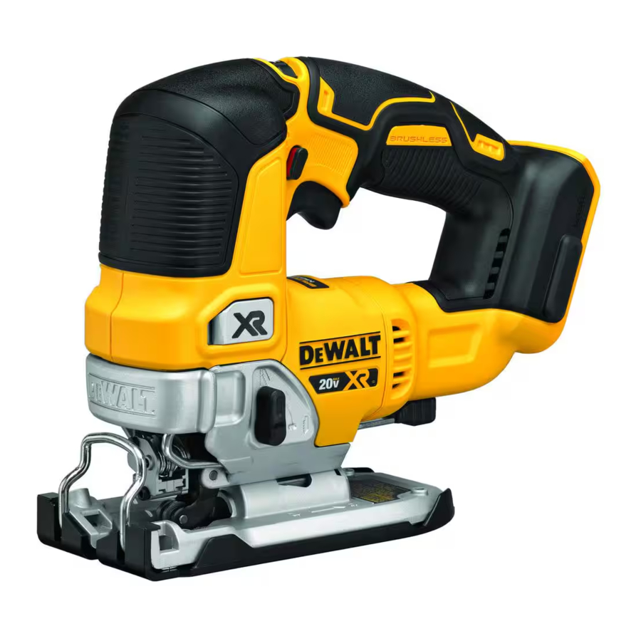
DeWalt XR DCS334, XR DCS335 Manual
- Manual (29 pages) ,
- Original instructions manual (105 pages)
Advertisement
Introduction
You have chosen a DeWALT tool. Years of experience, thorough product development and innovation make DeWALT one of the most reliable partners for professional power tool users.
Technical Data
| DCS334 | DCS335 | ||
| Voltage | VDC | 18 | 18 |
| Type | 2/11 | 1/10 | |
| Battery type | Li-Ion | Li-Ion | |
| No-load speed | min-1 | 0–3200 | 1000–3200 |
| Stroke length | mm | 26 | 26 |
| Cutting depth in: wood | mm | 135 | 135 |
| aluminum | mm | 25 | 25 |
| steel | mm | 10 | 10 |
| Bevel angle adjustment (l/r) | ˚ | 0–45 | 0–45 |
| Weight (without battery pack) | kg | 2.1 | 2.0 |
Noise values and vibration values (triax vector sum) according to EN62841-2-11:
| LPA (emission sound pressure level) | dB(A) | 88 | 88 |
| LWA (sound power level) | dB(A) | 96 | 96 |
| K ( uncertainty for the given sound level) | dB(A) | 3 | 4 |
| While cutting board Vibration emission value ah, B = | m/s2 | 5.2 | 7.7 |
| Uncertainty K = | m/s2 | 1.5 | 1.5 |
| While cutting sheet metal Vibration emission value ah, M = | m/s2 | 4.9 | 7.7 |
| Uncertainty K = | m/s2 | 1.6 | 3.1 |
The vibration and/or noise emission level given in this information sheet has been measured in accordance with a standardised test given in EN62841 and may be used to compare one tool with another. It may be used for a preliminary assessment of exposure.

The declared vibration and/or noise emission level represents the main applications of the tool. However, if the tool is used for different applications, with different accessories or is poorly maintained, the vibration and/or noise emission may differ. This may significantly increase the exposure level over the total working period.
An estimation of the level of exposure to vibration and/or noise should also take into account the times when the tool is switched off or when it is running but not actually doing the job. This may significantly reduce the exposure level over the total working period.
Identify additional safety measures to protect the operator from the effects of vibration and/or noise such as: maintain the tool and the accessories, keep the hands warm (relevant for vibration), organisation of work patterns.
Definitions: Safety Guidelines
The definitions below describe the level of severity for each signal word. Please read the manual and pay attention to these symbols.

Indicates an imminently hazardous situation which, if not avoided, will result in death or serious injury.
Indicates a potentially hazardous situation which, if not avoided, could result in death or serious injury.

Indicates a potentially hazardous situation which, if not avoided, may result in minor or moderate injury.
NOTICE: Indicates a practice not related to personal injury which, if not avoided, may result in property damage.
 Denotes risk of electric shock.
 Denotes risk of fire.
GENERAL POWER TOOL SAFETY WARNINGS
Read all safety warnings, instructions, illustrations and specifications provided with this power tool. Failure to follow all instructions listed below may result in electric shock, fire and/or serious injury.
SAVE ALL WARNINGS AND INSTRUCTIONS
FOR FUTURE REFERENCE
The term "power tool" in the warnings refers to your mains-operated (corded) power tool or battery-operated (cordless) power tool.
- Work Area Safety
- Keep work area clean and well lit. Cluttered or dark areas invite accidents.
- DO NOT operate power tools in explosive atmospheres, such as in the presence of flammable liquids, gases or dust. Power tools create sparks which may ignite the dust or fumes.
- Keep children and bystanders away while operating a power tool. Distractions can cause you to lose control.
- ) Remove any adjusting key or wrench before turning the power tool on. A wrench or a key left attached to a rotating part of the power tool may result in personal injury.
- Electrical Safety
- Power tool plugs must match the outlet. Never modify the plug in any way. DO NOT use any adapter plugs with earthed (grounded) power tools. Unmodified plugs and matching outlets will reduce risk of electric shock.
- Avoid body contact with earthed or grounded surfaces, such as pipes, radiators, ranges and refrigerators. There is an increased risk of electric shock if your body is earthed or grounded.
- DO NOT expose power tools to rain or wet conditions. Water entering a power tool will increase the risk of electric shock.
- DO NOT abuse the cord. Never use the cord for carrying, pulling or unplugging the power tool. Keep cord away from heat, oil, sharp edges or moving parts. Damaged or entangled cords increase the risk of electric shock.
- When operating a power tool outdoors, use an extension cord suitable for outdoor use. Use of a cord suitable for outdoor use reduces the risk of electric shock.
- If operating a power tool in a damp location is unavoidable, use a residual current device (RCD) protected supply. Use of an RCD reduces the risk of electric shock.
- Personal Safety
- Stay alert, watch what you are doing and use common sense when operating a power tool. DO NOT use a power tool while you are tired or under the influence of drugs, alcohol or medication. A moment of inattention while operating power tools may result in serious personal injury.
- Use personal protective equipment. Always wear eye protection. Protective equipment such as a dust mask, non-skid safety shoes, hard hat or hearing protection used for appropriate conditions will reduce personal injuries.
- Prevent unintentional starting. Ensure the switch is in the off position before connecting to power source and/or battery pack, picking up or carrying the tool. Carrying power tools with your finger on the switch or energising power tools that have the switch on invites accidents.
- Remove any adjusting key or wrench before turning the power tool on. A wrench or a key left attached to a rotating part of the power tool may result in personal injury.
- DO NOT overreach. Keep proper footing and balance at all times. This enables better control of the power tool in unexpected situations.
- Dress properly. DO NOT wear loose clothing or jewellery. Keep your hair and clothing away from moving parts. Loose clothes, jewellery or long hair can be caught in moving parts.
- If devices are provided for the connection of dust extraction and collection facilities, ensure these are connected and properly used. Use of dust collection can reduce dust-related hazards.
- DO NOT let familiarity gained from frequent use of tools allow you to become complacent and ignore tool safety principles. A careless action can cause severe injury within a fraction of a second.
- Power Tool Use and Care
- DO NOT force the power tool. Use the correct power tool for your application. The correct power tool will do the job better and safer at the rate for which it was designed.
- DO NOT use the power tool if the switch does not turn it on and off. Any power tool that cannot be controlled with the switch is dangerous and must be repaired.
- Disconnect the plug from the power source and/or remove the battery pack, if detachable, from the power tool before making any adjustments, changing accessories, or storing power tools. Such preventive safety measures reduce the risk of starting the power tool accidentally.
- Store idle power tools out of the reach of children and DO NOT allow persons unfamiliar with the power tool or these instructions to operate the power tool. Power tools are dangerous in the hands of untrained users.
- Maintain power tools and accessories. Check for misalignment or binding of moving parts, breakage of parts and any other condition that may affect the power tool's operation. If damaged, have the power tool repaired before use. Many accidents are caused by poorly maintained power tools.
- Keep cutting tools sharp and clean. Properly maintained cutting tools with sharp cutting edges are less likely to bind and are easier to control.
- Use the power tool, accessories and tool bits, etc. in accordance with these instructions, taking into account the working conditions and the work to be performed. Use of the power tool for operations different from those intended could result in a hazardous situation.
- Keep handles and grasping surfaces dry, clean and free from oil and grease. Slippery handles and grasping surfaces DO NOT allow for safe handling and control of the tool in unexpected situations.
- Battery Tool Use and Care
- Recharge only with the charger specified by the manufacturer. A charger that is suitable for one type of battery pack may create a risk of fire when used with another battery pack.
- Use power tools only with specifically designated battery packs. Use of any other battery packs may create a risk of injury and fire.
- When battery pack is not in use, keep it away from other metal objects, like paper clips, coins, keys, nails, screws or other small metal objects, that can make a connection from one terminal to another. Shorting the battery terminals together may cause burns or a fire.
- Under abusive conditions, liquid may be ejected from the battery; avoid contact. If contact accidentally occurs, flush with water. If liquid contacts eyes, additionally seek medical help. Liquid ejected from the battery may cause irritation or burns.
- DO NOT use a battery pack or tool that is damaged or modified. Damaged or modified batteries may exhibit unpredictable behaviour resulting in fire, explosion or risk of injury.
- DO NOT expose a battery pack or tool to fire or excessive temperature. Exposure to fire or temperature above 130°C may cause explosion.
- Follow all charging instructions and DO NOT charge the battery pack or tool outside the temperature range specified in the instructions. Charging improperly or at temperatures outside the specified range may damage the battery and increase the risk of fire.
- Service
- Have your power tool serviced by a qualified repair person using only identical replacement parts.This will ensure that the safety of the power tool is maintained.
- Never service damaged battery packs. Service of battery packs should only be performed by the manufacturer or authorised service providers.
Safety Instructions for Reciprocating Saws
- Hold the power tool by insulated gripping surfaces, when performing an operation where the cutting accessory may contact hidden wiring. Cutting accessory contacting a "live" wire may make exposed metal parts of the power tool "live" and could give the operator an electric shock.
- Use clamps or another practical way to secure and support the workpiece to a stable platform. Holding the workpiece by hand or against your body leaves it unstable and may lead to loss of control.
Additional Safety Instructions for Jig Saws
- Keep hands away from cutting area. Never reach underneath the workpiece for any reason. DO NOT insert fingers or thumb into the vicinity of the reciprocating blade and blade clamp. DO NOT stabilize the saw by gripping the shoe.
- Keep blades sharp. Dull or damaged blades may cause the saw to swerve or stall under pressure. Always use the appropriate type of saw blade for the workpiece material and type of cut.
- When cutting pipe or conduit, make sure that they are free from water, electrical wiring, etc.
- DO NOT touch the workpiece or the blade immediately after operating the tool. They can become very hot.
- Be aware of hidden hazards, before cutting into walls, floors or ceilings, check for the location of wiring and pipes.
- The blade will continue to move after releasing the switch. Always switch the tool off and wait for the saw blade to come to a complete standstill before putting the tool down.
Residual Risks
In spite of the application of the relevant safety regulations and the implementation of safety devices, certain residual risks cannot be avoided. These are:
- Impairment of hearing.
- Risk of accidents caused by the uncovered parts of the saw blade.
- Health hazards caused by breathing dust developed when sawing wood, especially oak, beech and MDF.
- Risk of personal injury due to flying particles.
- Risk of burns due to accessories becoming hot during operation.
- Risk of personal injury due to prolonged use.
Battery Type
The DCS334, DCS335 operates on an 18 volt battery pack.
These battery packs may be used: DCB181, DCB182, DCB183, DCB183B, DCB184, DCB184B, DCB185, DCB189, DCB546, DCB548, DCB187, DCB547. Refer to Technical Data for more information.
Package Contents
The package contains:
1 Cordless jigsaw
1 Anti‑scratch shoe cover
1 Dust port
1 Dust shroud
1 Dust chute
1 Li‑Ion battery pack (C1, D1, L1, M1, P1, S1, T1, X1, Y1 models)
2 Li‑Ion battery packs (C2, D2, L2, M2, P2, S2, T2, X2, Y2 models)
3 Li‑Ion battery packs (C3, D3, L3, M3, P3, S3, T3, X3, Y3, models)
1 Instruction manual
NOTE: Battery packs, chargers and kitboxes are not included with N models. Battery packs and chargers are not included with NT models. B models include Bluetooth® battery packs.
NOTE: The Bluetooth® word mark and logos are registered trademarks owned by the Bluetooth® SIG, Inc. and any use of such marks by DeWALT is under license. Other trademarks and trade names are those of their respective owners.
- Check for damage to the tool, parts or accessories which may have occurred during transport.
- Take the time to thoroughly read and understand this manual prior to operation.
Markings on Tool
The following pictograms are shown on the tool:
 | Read instruction manual before use. |
 | Wear ear protection. |
 | Wear eye protection. |
Date Code Position (Fig. A)
The production date code  consists of a 4‑digit year followed by a 2‑digit week and is extended by a 2‑digit factory code.
Description
Never modify the power tool or any part of it. Damage or personal injury could result.

- Speed trigger (DCS334), On/Off switch (DCS335)
- Lock‑off button (DCS334 only)
- Speed control dial
- Blade release latch
- Finger guard
- Orbital action lever
- Shoe
- Shoe bevel lever
- Handle
- Date code
Intended Use
Your DCS334 and DCS335 jig saws are designed for professional cutting of wood, steel, aluminium, plastic and ceramic material at various work sites (i.e., construction sites). DO NOT use under wet conditions or in the presence of flammable liquids or gases.
These heavy‑duty jigsaws are professional power tools.
DO NOT let children come into contact with the tool.
Supervision is required when inexperienced operators use this tool.
- Young children and the infirm. This appliance is not intended for use by young children or infirm persons without supervision.
- This product is not intended for use by persons (including children) suffering from diminished physical, sensory or mental abilities; lack of experience, knowledge or skills unless they are supervised by a person responsible for their safety. Children should never be left alone with this product.
ASSEMBLY AND ADJUSTMENTS
To reduce the risk of serious personal injury, turn tool off and disconnect battery pack before making any adjustments or removing/installing attachments or accessories. An accidental start-up can cause injury.
Use only DeWALT batteries and chargers.
Inserting and Removing the Battery Pack from the Tool (Fig. B)
NOTE: Make sure your battery pack  is fully charged. To Install the Battery Pack into the Tool Handle

- Align the battery pack with the rails inside the tool's handle (Fig. B).
- Slide it into the handle until the battery pack is firmly seated in the tool and ensure that you hear the lock snap into place.
To Remove the Battery Pack from the Tool
- Press the battery release button
![]() and firmly pull the battery pack out of the tool handle.
and firmly pull the battery pack out of the tool handle. - Insert battery pack into the charger.
 and firmly pull the battery pack out of the tool handle.
Fuel Gauge Battery Packs (Fig. B)
Some DeWALT battery packs include a fuel gauge, which consists of three green LED lights that indicate the level of charge remaining in the battery pack.
To actuate the fuel gauge, press and hold the fuel gauge button  . A combination of the three green LED lights will illuminate, designating the level of charge left. When the level of charge in the battery is below the usable limit, the fuel gauge will not illuminate and the battery will need to be recharged.
NOTE: The fuel gauge is only an indication of the charge left on the battery pack. It does not indicate tool functionality and is subject to variation based on product components, temperature and end‑user application.
Blade Installation and Removal (Fig. C, I)
To Install a Blade
NOTE: This jig saw uses only T‑shank jig saw blades.
NOTE: The DT2074 flush cutting blade is for use with DeWALT DCS334 and DCS335 jig saws only.
NOTE: When installing flush cutting blades (DT2074), the anti‑splinter insert (  , Fig. I) must be removed and the shoe must be in the 0 ° positive stop position.
NOTE: The correct saw blade must be selected for the material being cut.

- Hold open the blade release latch
![]() as shown in Figure C.
as shown in Figure C. - Insert the T‑shank blade into the clamp mechanism
![]() while guiding the back of the blade into the groove of the guide rollers
while guiding the back of the blade into the groove of the guide rollers ![]() .
. - The T‑shank should be completely inside the clamp mechanism.
- Release the blade release latch.
 as shown in Figure C.
 while guiding the back of the blade into the groove of the guide rollers
  .
.To Remove a Blade
DO NOT touch used blades, they may be hot. Personal injury may result.
- Lift the keyless blade release lever
![]() .
. - With a slight shake the blade will drop out.
- Release the keyless blade release lever.
Beveling the Shoe (Fig. D)
To Bevel the Shoe

- Remove the dust extraction accessories if they are mounted to the tool as the tool will not bevel if they are attached. Refer toDust Extraction section.
- Unlock the shoe by pulling the shoe bevel lever
![]() to the side.
to the side. - Slide the shoe
![]() forward to release it from the 0 ° positive stop position.
forward to release it from the 0 ° positive stop position.
NOTE: The shoe can be beveled to the left or to the right at a maximum of 45 ° in either direction. There are visible detents at 15 ° and 30 °. - Once the desired bevel angle is achieved, lock the shoe in position:
- For 0 ° and 45 ° bevel angles, slide the shoe back and lock the shoe by moving the bevel lever back under the body of the jig saw.
- For all angles between 0 ° and 45 °, lock with bevel lever only.
 to the side.
Cutting Action—Orbital or Straight (Fig. E)
This jig saw is equipped with four cutting actions, three orbital and one straight. Orbital action has a more aggressive blade motion and is designed for cutting in soft materials like wood or plastic. Orbital action provides a faster cut, but with a less smooth cut across the material. In orbital action, the blade moves forward during the cutting stroke in addition to the up and down motion.
NOTE: Metal or hardwoods should never be cut in orbital action. to adjust the cutting action, move the orbital action lever  between the four cutting positions: 0, 1, 2, and 3. Position 0 is straight cutting. Positions 1, 2, and 3 are orbital cutting. The aggressiveness of the cut increase as the lever is adjusted from one to three, with three being the most aggressive cut.

Dust Blower (Fig. F)
The dust blower  helps clear the cutting area of debris created from the blade.

Dust Extraction (Fig. A, G)
Dust can be hazardous to health. Always work with a dust extractor. Always observe the national regulations for work with dust emitting tools.
The dust extraction chute in combination with the dust extraction shroud helps extract dust from the workpiece surface, when connected to a suitable dust extraction system.
NOTE: The tool will not bevel if the dust extraction accessories are attached to the tool.

- Place the dust extraction shroud
![]() onto the finger guard
onto the finger guard ![]() (Fig. A) until it clicks into place.
(Fig. A) until it clicks into place. - Slide the dust chute
![]() from the back of the tool until it snaps into the dust shroud. Be sure the adapter end is facing up.
from the back of the tool until it snaps into the dust shroud. Be sure the adapter end is facing up. - To connect a vacuum to the dust chute
![]() , place a DeWALT AirLock (DWV9000), found on all full size DeWALT vacuum hoses, over the dust collection port, and twist the collar to lock it into place. The dust chute will also fit a standard 35 mm connector.
, place a DeWALT AirLock (DWV9000), found on all full size DeWALT vacuum hoses, over the dust collection port, and twist the collar to lock it into place. The dust chute will also fit a standard 35 mm connector.
 onto the finger guard
  (Fig. A) until it clicks into place.
 from the back of the tool until it snaps into the dust shroud. Be sure the adapter end is facing up.
Removable Anti‑Scratch Shoe Cover (Fig. H)
The anti‑scratch shoe cover  should be used when cutting surfaces that scratch easily, such as laminate, veneer or paint. To attach anti‑scratch shoe cover , place the front of the shoe
  into the front of the anti‑scratch shoe cover and lower the jig saw. The anti‑scratch shoe cover will click securely onto the rear of the shoe.
To remove anti‑scratch shoe cover, grasp the anti‑scratch shoe cover from the bottom; holding onto the two rear tabs  remove the anti‑scratch shoe cover.

Anti‑Splinter Insert (Fig. H, I)
NOTE: DO NOT use the anti‑splinter insert with the flush cutting blade DT74.
The anti‑splinter insert should be used when trying to minimize tear‑out, especially when cutting veneer, laminate, or finished surfaces, such as paint. The anti‑splinter insert should be installed into the anti‑scratch shoe cover . If the no‑mar cover is not used, install anti‑splinter insert into shoe .

Setting the Electronic Sawing Speed (Fig. A, J)

DCS334
To preset the sawing speed, turn the speed control dial  to the desired level. The higher the number on the speed control dial, the higher the sawing speed. The sawing speed varies with the pressure exerted on the variable speed trigger
  , but will not exceed the speed that is set by the speed control dial . The required setting depends on the thickness and kind of material.
NOTE: Use high speeds for sawing soft materials such as wood.
DCS335
The speed control dial can be used for advance setting of the required range of speed.
- Turn the electronic control dial to the required level. The DCS335 will turn on at that speed when the on/off switch is moved to the ON position. The required setting depends on the thickness and kind of material.
NOTE: Use high speeds for sawing soft materials such as wood.
OPERATION
Instructions for Use
Always observe the safety instructions and applicable regulations.
To reduce the risk of serious personal injury, turn tool off and disconnect battery pack before making any adjustments or removing/installing attachments or accessories. An accidental start-up can cause injury.
Always wear proper personal hearing protection. Under some conditions and duration of use, noise from this product may contribute to hearing loss.
- Make sure your workpiece is well secured. Remove nails, screws and other fasteners that may damage the blade.
- Check that there is sufficient space for the blade underneath the workpiece. DO NOT cut materials that are thicker than the maximum cutting depth.
- Use sharp saw blades only. Damaged or bent saw blades must be removed immediately.
- Never run your tool without a saw blade.
- For optimal results, move the tool smoothly and constantly over the workpiece. DO NOT exert lateral pressure on the saw blade. Keep the shoe flat on the workpiece. When sawing curves, circles or other round shapes, push the tool gently forward.
- Wait until the tool has come to a standstill before removing the saw blade from the workpiece. After sawing the blade may be very hot. DO NOT touch.
Proper Hand Position (Fig. K)
To reduce the risk of serious personal injury, ALWAYS use proper hand position as shown.
To reduce the risk of serious personal injury, ALWAYS hold securely in anticipation of a sudden reaction.
Proper hand position requires one hand on the main handle  . Keep other hand clear of cutter area.

Lock‑Off Button and Variable Speed Trigger (Fig. A)
DCS334
To lock the variable speed trigger , press the lock‑off button  . When the lock‑off button is depressed to the lock icon, the unit is locked.
Always lock the trigger switch when carrying or storing the tool to eliminate unintentional starting.
To unlock the trigger switch, press the lock‑off button. When the lock‑off button is depressed to the unlock icon, the unit is unlocked.
NOTE: The lock‑off button is colored red to indicate when the switch is in its unlocked position.
To start the DCS334 jig saw, squeeze the variable speed trigger .
To slow and stop the jig saw, release the trigger.
As the trigger is pressed in, the strokes‑per‑minute continue to increase, but up to the maximum speed of the tool. As the trigger is released, the blade strokes‑per‑minute reduce.
NOTE: This tool has no provision to lock the switch in the ON position, and should never be locked ON by any other means.
On/Off Switch (Fig. A)
DCS335
Move the on/off switch to the OFF position before inserting the battery pack.
To start the DCS335 jig saw, move the on/off switch to the ON position. To turn the jig saw off, move the on/off switch to the OFF position.
Worklights
The worklights are located on either side of the blade. To turn on the worklight, depress the trigger (DCS334) or switch on the on/off switch (DCS335). Worklights will remain on 20 seconds after the tool is turned on, or as long as your cut lasts.
NOTE: The worklights are for lighting the immediate work surface and are not intended to be used as a flashlight.
Cutting
The jig saw should not be operated with the shoe removed or serious personal injury may result.
Pocket Cutting (Fig. L)
A pocket cut is an easy method of making an inside cut. The saw can be inserted directly into a panel or board without first drilling a lead or pilot hole. In pocket cutting, measure the surface to be cut and mark clearly with a pencil. Next tip the saw forward until the front end of the shoe sits firmly on the work surface and the blade clears the work through its full stroke. Switch the tool on and allow it to attain maximum speed. Grip the saw firmly and lower the back edge of tool slowly until the blade reaches its complete depth. Hold the shoe flat against the wood and begin cutting. DO NOT remove blade from cut while it is still moving. Blade must come to a complete stop.

Flush Cutting (Fig. M)
A flush cut is necessary when finishing off cuts up to a wall or an obstacle, such as back‑splash. One of the easiest ways to accomplish the flush cut is to use a flush cutting blade (DT2074). The flush cutting blade provides the reach necessary to cut right up to the front edge of the jig saw shoe. Remove the anti‑splinter insert and return the shoe to the 0 ° positive stop position before installing and using the flush cutting blade. For the best cut quality the flush cutting blade should be used in the 0 or 1 orbital position. The flush cutting blade should not be used to start the cut because the flush cutting blade prevents the shoe from being supported by the work surface. Use wood cutting practices explained below.

Wood Cutting
Support the workpiece adequately at all times. Use the higher speed setting for cutting wood. DO NOT attempt to turn the tool on when blade is against material to be cut. This could stall the motor. Place the front of shoe on the material to be cut and hold the jig saw shoe firmly against the wood while cutting. Don't force the tool; let the blade cut at its own speed. When the cut is complete, turn the jig saw off. Let blade come to a complete stop and then lay the saw aside before loosening the work.
Metal Cutting
In cutting thin gauge sheet metals, it is best to clamp wood to the bottom of sheet metal; this will insure a clean cut without the risk of vibration or tearing of metal. Always remember to use a finer blade for ferrous metals (for those that have a high iron content); and use a coarser blade for non‑ferrous metals (those that DO NOT have an iron content). Use a high speed setting for cutting soft metals (aluminum, copper, brass, mild steel, galvanized pipe, conduit, sheet metal, etc.). Use lower speed to cut plastics, tile, laminate, hard metals, and cast iron.
MAINTENANCE
Your power tool has been designed to operate over a long period of time with a minimum of maintenance. Continuous satisfactory operation depends upon proper tool care and regular cleaning.
To reduce the risk of serious personal injury, turn tool off and disconnect battery pack before making any adjustments or removing/installing attachments or accessories. An accidental start-up can cause injury. The charger and battery pack are not serviceable.
Lubrication
Your power tool requires no additional lubrication.
Cleaning

Electrical shock and mechanical hazard. Disconnect the electrical appliance from the power source before cleaning.
To ensure safe and efficient operation, always keep the electrical appliance and the ventilation slots clean.
Never use solvents or other harsh chemicals for cleaning the non-metallic parts of the tool. These chemicals may weaken the materials used in these parts. Use a cloth dampened only with water and mild soap. Never let any liquid get inside the tool; never immerse any part of the tool into a liquid. Ventilation slots can be cleaned using a dry, soft non‑metallic brush and/or a suitable vacuum cleaner. DO NOT use water or any cleaning solutions. Wear approved eye protection and an approved dust mask.
Optional Accessories
Since accessories, other than those offered by DeWALT, have not been tested with this product, use of such accessories with this tool could be hazardous. To reduce the risk of injury, only DeWALT-recommended accessories should be used with this product.
Consult your dealer for further information on the appropriate accessories.
Documents / ResourcesDownload manual
Here you can download full pdf version of manual, it may contain additional safety instructions, warranty information, FCC rules, etc.
Advertisement


Need help?
Do you have a question about the XR DCS334 and is the answer not in the manual?
Questions and answers