DeWalt XR DCF891, XR DCF892, XR DCF891P2 Manual
- Original instructions manual (60 pages) ,
- Original instructions manual (17 pages) ,
- Original instructions manual (145 pages)
Advertisement
Technical Data
| DCF891 | DCF892 | ||
| Voltage | VDC | 18(20 Max) | 18(20 Max) |
| Battery type | Li-Ion | Li-Ion | |
| Power output | W | 760 | 760 |
| No load speed | min-1 | 0–2000 | 0–2000 |
| Impact rate | min-1 | 0–3250 | 0–3250 |
| Max tightening torque | |||
| Precision Wrench mode | Nm | 812 | 812 |
| Low Mode | Nm | 136 | 136 |
| Medium mode | Nm | 406 | 406 |
| High mode | Nm | 812 | 812 |
| Max breakaway torque | Nm | 1084 | 1084 |
| Tool holder | mm | 12.7 | 12.7 |
| Weight (without battery pack) | kg | 1.67 | 1.67 |
| Vibration emission value | |||
| ah = | m/s2 | 10 | 10 |
| Uncertainty K = | m/s2 | 1.7 | 1.7 |

The declared vibration and/or noise emission level represents the main applications of the tool. However if the tool is used for different applications, with different accessories or poorly maintained, the vibration and/or noise emission may differ. This may significantly increase the exposure level over the total working period.
An estimation of the level of exposure to vibration and/or noise should also take into account the times when the tool is switched off or when it is running but not actually doing the job. This may significantly reduce the exposure level over the total working period.
Identify additional safety measures to protect the operator from the effects of vibration and/or noise such as: maintain the tool and the accessories, keep the hands warm (relevant for vibration), organisation of work patterns.
To reduce the risk of injury, read the instruction manual.
| Batteries | Chargers / Charge Times (Minutes) | ||||||||||
| Cat# | VDC | Ah | Weight(kg) | DCB104 | DCB107 | DCB112 | DCB115 | DCB117 | DCB118 | DCB132 | DCB1112 |
| DCB546/DCB606 | 18/54 (20/60 Max) | 6.0/2.0 | 1.05 | 60 | 270 | 170 | 90 | 40 | 60 | 90 | 40 |
| DCB547/DCB609 | 18/54 (20/60 Max) | 9.0/3.0 | 1.46 | 75* | 420 | 270 | 135* | 60 | 75* | 135* | 60 |
| DCB548/DCB612 | 18/54 (20/60 Max) | 12.0/4.0 | 1.44 | 120 | 540 | 350 | 180 | 80 | 120 | 180 | 80 |
| DCB181 | 18 (20 Max) | 1.5 | 0.35 | 22 | 70 | 45 | 22 | 22 | 22 | 22 | 22 |
| DCB182/DCB204 | 18 (20 Max) | 4.0 | 0.61 | 60/40** | 185 | 120 | 60 | 60/40** | 60/40** | 60 | 60/40** |
| DCB183/DCB203 | 18 (20 Max) | 2.0 | 0.40 | 30 | 90 | 60 | 30 | 30 | 30 | 30 | 30 |
| DCB184/DCB205 | 18 (20 Max) | 5.0 | 0.62 | 75/50** | 240 | 150 | 75 | 75/50** | 75/50** | 75 | 75/50** |
| DCB185 | 18 (20 Max) | 1.3 | 0.35 | 22 | 60 | 40 | 22 | 22 | 22 | 22 | 22 |
| DCB187 | 18 (20 Max) | 3.0 | 0.54 | 45 | 140 | 90 | 45 | 45 | 45 | 45 | 45 |
| DCB189/DCB240 | 18 (20 Max) | 4.0 | 0.54 | 60 | 185 | 120 | 60 | 60 | 60 | 60 | 60 |
| DCB186 | 18 (20 Max) | 6.0 | 0.95 | 60 | 270 | 170 | 90 | 60 | 60 | 90 | 60 |
*Date code 201811475B or later
**Date code 201536 or later
Safety Symbols Definitions
The definitions below describe the level of severity for each signal word. Please read the manual and pay attention to these symbols.

Indicates an imminently hazardous situation which, if not avoided, will result in death or serious injury.
Indicates a potentially hazardous situation which, if not avoided, could result in death or serious injury.

Indicates a potentially hazardous situation which, if not avoided, may result in minor or moderate injury.
NOTICE: Indicates a practice not related to personal injury which, if not avoided, may result in property damage.
 Denotes risk of electric shock.
 Denotes risk of fire.
General Power Tool Safety Warnings

Read all safety warnings, instructions, illustrations and specifications provided with this power tool. Failure to follow all instructions listed below may result in electric shock, fire and/or serious injury.
SAVE ALL WARNINGS AND INSTRUCTIONS
FOR FUTURE REFERENCE
The term "power tool" in the warnings refers to your mains‑operated (corded) power tool or battery‑operated (cordless) power tool.
- Work Area Safety
- Keep work area clean and well lit. Cluttered or dark areas invite accidents.
- Do not operate power tools in explosive atmospheres, such as in the presence of flammable liquids, gases or dust. Power tools create sparks which may ignite the dust or fumes.
- Keep children and bystanders away while operating a power tool. Distractions can cause you to lose control.
- Electrical Safety
![shock hazard]() Power tool plugs must match the outlet. Never modify the plug in any way. Do not use any adapter plugs with earthed (grounded) power tools. Unmodified plugs and matching outlets will reduce risk of electric shock.
Power tool plugs must match the outlet. Never modify the plug in any way. Do not use any adapter plugs with earthed (grounded) power tools. Unmodified plugs and matching outlets will reduce risk of electric shock.![shock hazard]() Avoid body contact with earthed or grounded surfaces, such as pipes, radiators, ranges and refrigerators. There is an increased risk of electric shock if your body is earthed or grounded.
Avoid body contact with earthed or grounded surfaces, such as pipes, radiators, ranges and refrigerators. There is an increased risk of electric shock if your body is earthed or grounded.![shock hazard]() Do not expose power tools to rain or wet conditions. Water entering a power tool will increase the risk of electric shock.
Do not expose power tools to rain or wet conditions. Water entering a power tool will increase the risk of electric shock.![shock hazard]() Do not abuse the cord. Never use the cord for carrying, pulling or unplugging the power tool. Keep cord away from heat, oil, sharp edges or moving parts. Damaged or entangled cords increase the risk of electric shock.
Do not abuse the cord. Never use the cord for carrying, pulling or unplugging the power tool. Keep cord away from heat, oil, sharp edges or moving parts. Damaged or entangled cords increase the risk of electric shock.![shock hazard]() When operating a power tool outdoors, use an extension cord suitable for outdoor use. Use of a cord suitable for outdoor use reduces the risk of electric shock.
When operating a power tool outdoors, use an extension cord suitable for outdoor use. Use of a cord suitable for outdoor use reduces the risk of electric shock.![shock hazard]() If operating a power tool in a damp location is unavoidable, use a residual current device (RCD) protected supply. Use of an RCD reduces the risk of electric shock.
If operating a power tool in a damp location is unavoidable, use a residual current device (RCD) protected supply. Use of an RCD reduces the risk of electric shock.
- Personal Safety
- Stay alert, watch what you are doing and use common sense when operating a power tool. Do not use a power tool while you are tired or under the influence of drugs, alcohol or medication. A moment of inattention while operating power tools may result in serious personal injury.
- Use personal protective equipment. Always wear eye protection. Protective equipment such as a dust mask, non‑skid safety shoes, hard hat or hearing protection used for appropriate conditions will reduce personal injuries.
- Prevent unintentional starting. Ensure the switch is in the off‑position before connecting to power source and/or battery pack, picking up or carrying the tool. Carrying power tools with your finger on the switch or energising power tools that have the switch on invites accidents.
- Remove any adjusting key or wrench before turning the power tool on. A wrench or a key left attached to a rotating part of the power tool may result in personal injury.
- Do not overreach. Keep proper footing and balance at all times. This enables better control of the power tool in unexpected situations.
- Dress properly. Do not wear loose clothing or jewellery. Keep your hair and clothing away from moving parts. Loose clothes, jewellery or long hair can be caught in moving parts.
- If devices are provided for the connection of dust extraction and collection facilities, ensure these are connected and properly used. Use of dust collection can reduce dust‑related hazards.
- Do not let familiarity gained from frequent use of tools allow you to become complacent and ignore tool safety principles. A careless action can cause severe injury within a fraction of a second.
- Power Tool Use and Care
- Do not force the power tool. Use the correct power tool for your application. The correct power tool will do the job better and safer at the rate for which it was designed.
- Do not use the power tool if the switch does not turn it on and off. Any power tool that cannot be controlled with the switch is dangerous and must be repaired.
- Disconnect the plug from the power source and/ or remove the battery pack, if detachable, from the power tool before making any adjustments, changing accessories, or storing power tools. Such preventive safety measures reduce the risk of starting the power tool accidentally.
- Store idle power tools out of the reach of children and do not allow persons unfamiliar with the power tool or these instructions to operate the power tool. Power tools are dangerous in the hands of untrained users.
- Maintain power tools and accessories. Check for misalignment or binding of moving parts, breakage of parts and any other condition that may affect the power tool's operation. If damaged, have the power tool repaired before use. Many accidents are caused by poorly maintained power tools.
- Keep cutting tools sharp and clean. Properly maintained cutting tools with sharp cutting edges are less likely to bind and are easier to control.
- Use the power tool, accessories and tool bits etc. in accordance with these instructions, taking into account the working conditions and the work to be performed. Use of the power tool for operations different from those intended could result in a hazardous situation.
- Keep handles and grasping surfaces dry, clean and free from oil and grease. Slippery handles and grasping surfaces do not allow for safe handling and control of the tool in unexpected situations.
- Battery Tool Use and Care
![burn hazard]() Recharge only with the charger specified by the manufacturer. A charger that is suitable for one type of battery pack may create a risk of fire when used with another battery pack.
Recharge only with the charger specified by the manufacturer. A charger that is suitable for one type of battery pack may create a risk of fire when used with another battery pack.![burn hazard]() Use power tools only with specifically designated battery packs. Use of any other battery packs may create a risk of injury and fire.
Use power tools only with specifically designated battery packs. Use of any other battery packs may create a risk of injury and fire.![]()
When battery pack is not in use, keep it away from other metal objects, like paper clips, coins, keys, nails, screws or other small metal objects, that can make a connection from one terminal to another. Shorting the battery terminals together may cause burns or a fire.![]()
Under abusive conditions, liquid may be ejected from the battery; avoid contact. If contact accidentally occurs, flush with water. If liquid contacts eyes, additionally seek medical help. Liquid ejected from the battery may cause irritation or burns.![burn hazard]() Do not use a battery pack or tool that is damaged or modified. Damaged or modified batteries may exhibit unpredictable behaviour resulting in fire, explosion or risk of injury.
Do not use a battery pack or tool that is damaged or modified. Damaged or modified batteries may exhibit unpredictable behaviour resulting in fire, explosion or risk of injury.- Do not expose a battery pack or tool to fire or excessive temperature. Exposure to fire or temperature above 130°C may cause explosion.
![burn hazard]() Follow all charging instructions and do not charge the battery pack or tool outside the temperature range specified in the instructions. Charging improperly or at temperatures outside the specified range may damage the battery and increase the risk of fire.
Follow all charging instructions and do not charge the battery pack or tool outside the temperature range specified in the instructions. Charging improperly or at temperatures outside the specified range may damage the battery and increase the risk of fire.
- Service
- Have your power tool serviced by a qualified repair person using only identical replacement parts. This will ensure that the safety of the power tool is maintained.
- Never service damaged battery packs. Service of battery packs should only be performed by the manufacturer or authorized service providers.
Product Safety Warnings
All Operations
![shock hazard]() Hold the power tool by insulated gripping surfaces, when performing an operation where the fastener may contact hidden wiring.Fasteners contacting a "live" wire may make exposed metal parts of the power tool "live" and could give the operator an electric shock.
Hold the power tool by insulated gripping surfaces, when performing an operation where the fastener may contact hidden wiring.Fasteners contacting a "live" wire may make exposed metal parts of the power tool "live" and could give the operator an electric shock.- Wear ear protectors during use. Exposure to noise can cause hearing loss.
Impact wrenches are not torque wrenches. DO NOT use this tool for tightening fasteners to specified torques. An independent, calibrated torque measurement device such as a torque wrench should be used when under tightened or over tightened fasteners can lead to the failure of the joint.
Chargers
DeWALT chargers require no adjustment and are designed to be as easy as possible to operate.
Electrical Safety
The electric motor has been designed for one voltage only. Always check that the battery pack voltage corresponds to the voltage on the rating plate. Also make sure that the voltage of your charger corresponds to that of your mains.
Your DeWALT charger is double insulated in accordance with IEC60335; therefore no earth wire is required.

If the supply cord is damaged, it must be replaced only by DeWALT or an authorised service organisation.
Using an Extension Cable
An extension cord should not be used unless absolutely necessary. Use an approved extension cable suitable for the power input of your charger (see Technical Data). The minimum conductor size is 1 mm2; the maximum length is 30 m.
When using a cable reel, always unwind the cable completely.
Important Safety Instructions for All Battery Chargers
SAVE THESE INSTRUCTIONS: This manual contains important safety and operating instructions for compatible battery chargers (refer to Technical Data).
- Before using charger, read all instructions and cautionary markings on charger, battery pack, and product using battery pack.
Shock hazard. Do not allow any liquid to get inside charger. Electric shock may result.
We recommend the use of a residual current device with a residual current rating of 30mA or less.

Burn hazard. To reduce the risk of injury, charge only DeWALT rechargeable batteries. Other types of batteries may burst causing personal injury and damage.
Children should be supervised to ensure that they do not play with the appliance.
NOTICE: Under certain conditions, with the charger plugged into the power supply, the exposed charging contacts inside the charger can be shorted by foreign material. Foreign materials of a conductive nature such as, but not limited to, steel wool, aluminum foil or any buildup of metallic particles should be kept away from charger cavities. Always unplug the charger from the power supply when there is no battery pack in the cavity. Unplug charger before attempting to clean.
- DO NOT attempt to charge the battery pack with any chargers other than the ones in this manual. The charger and battery pack are specifically designed to work together.
![burn hazard]()
![shock hazard]()
These chargers are not intended for any uses other than charging DeWALT rechargeable batteries. Any other uses may result in risk of fire, electric shock or electrocution.- Do not expose charger to rain or snow.
- Pull by plug rather than cord when disconnecting charger. This will reduce risk of damage to electric plug and cord.
- Make sure that cord is located so that it will not be stepped on, tripped over, or otherwise subjected to damage or stress.
![burn hazard]()
![shock hazard]()
Do not use an extension cord unless it is absolutely necessary. Use of improper extension cord could result in risk of fire, electric shock, or electrocution.- Do not place any object on top of charger or place the charger on a soft surface that might block the ventilation slots and result in excessive internal heat. Place the charger in a position away from any heat source. The charger is ventilated through slots in the top and the bottom of the housing.
- Do not operate charger with damaged cord or plug— have them replaced immediately.
- Do not operate charger if it has received a sharp blow, been dropped, or otherwise damaged in any way. Take it to an authorised service centre.
![burn hazard]()
![shock hazard]()
Do not disassemble charger; take it to an authorised service centre when service or repair is required. Incorrect reassembly may result in a risk of electric shock, electrocution or fire.- In case of damaged power supply cord, the supply cord must be replaced immediately by the manufacturer, its service agent or similar qualified person to prevent any hazard.
![shock hazard]() Disconnect the charger from the outlet before attempting any cleaning. This will reduce the risk of electric shock. Removing the battery pack will not reduce this risk.
Disconnect the charger from the outlet before attempting any cleaning. This will reduce the risk of electric shock. Removing the battery pack will not reduce this risk.- NEVER attempt to connect two chargers together.
- The charger is designed to operate on standard 220-240V household electrical power. Do not attempt to use it on any other voltage. This does not apply to the vehicular charger.
Charging a Battery

(Fig. B)
- Plug the charger into an appropriate outlet before inserting battery pack.
- Insert the battery pack
![]() into the charger, making sure the battery pack is fully seated in the charger. The red (charging) light will blink repeatedly indicating that the charging process has started.
into the charger, making sure the battery pack is fully seated in the charger. The red (charging) light will blink repeatedly indicating that the charging process has started. - The completion of charge will be indicated by the red light remaining ON continuously. The battery pack is fully charged and may be used at this time or left in the charger. To remove the battery pack from the charger, push the battery release button
![]() on the battery pack.
on the battery pack.
 into the charger, making sure the battery pack is fully seated in the charger. The red (charging) light will blink repeatedly indicating that the charging process has started.
 on the battery pack.
NOTE: To ensure maximum performance and life of lithium‑ion battery packs, charge the battery pack fully before first use.
Charger Operation
Refer to the indicators below for the charge status of the battery pack.

* The red light will continue to blink, but a yellow indicator light will be illuminated during this operation. Once the battery pack has reached an appropriate temperature, the yellow light will turn off and the charger will resume the charging procedure.
The compatible charger(s) will not charge a faulty battery pack. The charger will indicate faulty battery by refusing to light.
NOTE: This could also mean a problem with a charger.
If the charger indicates a problem, take the charger and battery pack to be tested at an authorised service centre.
Hot/Cold Pack Delay
When the charger detects a battery pack that is too hot or too cold, it automatically starts a Hot/Cold Pack Delay, suspending charging until the battery pack has reached an appropriate temperature. The charger then automatically switches to the pack charging mode. This feature ensures maximum battery pack life.
A cold battery pack will charge at a slower rate than a warm battery pack. The battery pack will charge at that slower rate throughout the entire charging cycle and will not return to maximum charge rate even if the battery pack warms.
The DCB118 charger is equipped with an internal fan designed to cool the battery pack. The fan will turn on automatically when the battery pack needs to be cooled. Never operate the charger if the fan does not operate properly or if ventilation slots are blocked. Do not permit foreign objects to enter the interior of the charger.
Electronic Protection system
XR Li‑Ion tools are designed with an Electronic Protection System that will protect the battery pack against overloading, overheating or deep discharge.
The tool will automatically turn off if the Electronic Protection System engages. If this occurs, place the lithium‑ion battery pack on the charger until it is fully charged.
Wall Mounting
These chargers are designed to be wall mountable or to sit upright on a table or work surface. If wall mounting, locate the charger within reach of an electrical outlet, and away from a corner or other obstructions which may impede air flow. Use the back of the charger as a template for the location of the mounting screws on the wall. Mount the charger securely using drywall screws (purchased separately) at least 25.4 mm long with a screw head diameter of 7–9 mm, screwed into wood to an optimal depth leaving approximately 5.5 mm of the screw exposed. Align the slots on the back of the charger with the exposed screws and fully engage them in the slots.
Charger Cleaning Instructions
Shock hazard. Disconnect the charger from the AC outlet before cleaning. Dirt and grease may be removed from the exterior of the charger using a cloth or soft non‑metallic brush. Do not use water or any cleaning solutions. Never let any liquid get inside the tool; never immerse any part of the tool into a liquid.
Battery Packs
Important Safety Instructions for All Battery Packs
When ordering replacement battery packs, be sure to include catalogue number and voltage.
The battery pack is not fully charged out of the carton. Before using the battery pack and charger, read the safety instructions below. Then follow charging procedures outlined.
READ ALL INSTRUCTIONS
- Do not charge or use battery in explosive atmospheres, such as in the presence of flammable liquids, gases or dust. Inserting or removing the battery from the charger may ignite the dust or fumes.
- Never force battery pack into charger. Do not modify battery pack in any way to fit into a non‑compatible charger as battery pack may rupture causing serious personal injury.
- Charge the battery packs only in DeWALT chargers.
- DO NOT splash or immerse in water or other liquids.
- Do not store or use the tool and battery pack in locations where the temperature may fall below 4 ˚C (39.2 ˚F) (such as outside sheds or metal buildings in winter), or reach or exceed 40 ˚C (104 ˚F) (such as outside sheds or metal buildings in summer).
- Do not incinerate the battery pack even if it is severely damaged or is completely worn out. The battery pack can explode in a fire. Toxic fumes and materials are created when lithium‑ion battery packs are burned.
- If battery contents come into contact with the skin, immediately wash area with mild soap and water. If battery liquid gets into the eye, rinse water over the open eye for 15 minutes or until irritation ceases. If medical attention is needed, the battery electrolyte is composed of a mixture of liquid organic carbonates and lithium salts.
- Contents of opened battery cells may cause respiratory irritation. Provide fresh air. If symptoms persists, seek medical attention.
Burn hazard. Battery liquid may be flammable if exposed to spark or flame.
Never attempt to open the battery pack for any reason. If battery pack case is cracked or damaged, do not insert into charger. Do not crush, drop or damage battery pack. Do not use a battery pack or charger that has received a sharp blow, been dropped, run over or damaged in any way (i.e., pierced with a nail, hit with a hammer, stepped on). Electric shock or electrocution may result. Damaged battery packs should be returned to service centre for recycling.
Fire hazard. Do not store or carry the battery pack so that metal objects can contact exposed battery terminals. For example, do not place the battery pack in aprons, pockets, tool boxes, product kit boxes, drawers, etc., with loose nails, screws, keys, etc.
When not in use, place tool on its side on a stable surface where it will not cause a tripping or falling hazard. Some tools with large battery packs will stand upright on the battery pack but may be easily knocked over.
Transportation
Fire hazard. Transporting batteries can possibly cause fire if the battery terminals inadvertently come in contact with conductive materials. When transporting batteries, make sure that the battery terminals are protected and well insulated from materials that could contact them and cause a short circuit. NOTE: Lithium‑ion batteries should not be put in checked baggage.
DeWALT batteries comply with all applicable shipping regulations as prescribed by industry and legal standards which include UN Recommendations on the Transport of Dangerous Goods; International Air Transport Association (IATA) Dangerous Goods Regulations, International Maritime Dangerous Goods (IMDG) Regulations, and the European Agreement Concerning The International Carriage of Dangerous Goods by Road (ADR). Lithium‑ion cells and batteries have been tested to section 38.3 of the UN Recommendations on the Transport of Dangerous Goods Manual of Tests and Criteria.
In most instances, shipping a DeWALT battery pack will be excepted from being classified as a fully regulated Class 9 Hazardous Material. In general, only shipments containing a lithium‑ion battery with an energy rating greater than 100 Watt Hours (Wh) will require being shipped as fully regulated Class 9. All lithium‑ion batteries have the Watt Hour rating marked on the pack. Furthermore, due to regulation complexities, DeWALT does not recommend air shipping lithium‑ion battery packs alone regardless of Watt Hour rating. Shipments of tools with batteries (combo kits) can be air shipped as excepted if the Watt Hour rating of the battery pack is no greater than 100 Wh.
Regardless of whether a shipment is considered excepted or fully regulated, it is the shipper's responsibility to consult the latest regulations for packaging, labeling/marking and documentation requirements.
The information provided in this section of the manual is provided in good faith and believed to be accurate at the time the document was created. However, no warranty, expressed or implied, is given. It is the buyer's responsibility to ensure that its activities comply with the applicable regulations.
Transporting the FlEXVOLT Battery
The DeWALT FLEXVOLT battery has two modes: Use and Transport.
Use Mode: When the FLEXVOLT battery stands alone or is in a DeWALT 18V(20V Max) product, it will operate as an 18V(20V Max) battery. When the FLEXVOLT battery is in a 54V(60V Max) or a 108V(120V Max) (two 54V(60V Max) batteries) product, it will operate as a 54V(60V Max) battery.
Transport Mode: When the cap is attached to the FLEXVOLT battery, the battery is in Transport mode. Keep the cap for shipping.
When in Transport mode, strings of cells are electrically disconnected within the pack resulting in 3 batteries with a lower Watt hour (Wh) rating as compared to 1 battery with a higher Watt hour rating. This increased quantity of 3 batteries with the lower Watt hour rating can exempt the pack from certain shipping regulations that are imposed upon the higher Watt hour batteries.

For example, the Transport Wh rating might indicate 3 x 36 Wh, meaning 3 batteries of 36 Wh each.
The Use Wh rating might indicate 108 Wh (1 battery implied).

Example of Use and Transport Label Marking
Storage Recommendations
- The best storage place is one that is cool and dry away from direct sunlight and excess heat or cold. For optimum battery performance and life, store battery packs at room temperature when not in use.
- For long storage, it is recommended to store a fully charged battery pack in a cool, dry place out of the charger for optimal results.
NOTE: Battery packs should not be stored completely depleted of charge. The battery pack will need to be recharged before use.
Labels on Charger and Battery Pack
In addition to the pictographs used in this manual, the labels on the charger and the battery pack may show the L Read instruction manual before use. following pictographs:
 | See Technical Data for charging time. |
 | Do not probe with conductive objects. |
 | Do not charge damaged battery packs. |
 | Do not expose to water. |
 | Have defective cords replaced immediately |
 | Charge only between 4 ˚C and 40 ˚C. |
 | Only for indoor use. |
 | Charge DeWALT battery packs only with designated DeWALT chargers. Charging battery packs other than the designated DeWALT batteries with a DeWALT charger may make them burst or lead to other dangerous situations. |
 | Do not incinerate the battery pack. |
 | USE (without transport cap). Example: Wh rating indicates 108 Wh (1 battery with 108 Wh). |
 | TRANSPORT (with built‑in transport cap). Example: Wh rating indicates 3 x 36 Wh (3 batteries of 36 Wh). |
Battery Type
The following tools operate on an 18 (20 Max)volt battery pack: DCF891, DCF892
These battery packs may be used: DCB181, DCB182, DCB183, DCB183B, DCB183G, DCB184, DCB184B, DCB184G, DCB184LR, DCB185, DCB187, DCB189, DCB203, DCB204, DCB205, DCB546, DCB547, DCB548, DCB606, DCB609, DCB612. Refer to Technical Data for more information.
Package Contents
The package contains:
1 Impact wrench
1 Charger
1 Belt hook
1 Li‑Ion battery pack (C1, D1, E1, L1, M1, P1, S1, T1, X1, Y1 models)
2 Li‑Ion battery packs (C2, D2, E2, L2, M2, P2, S2, T2, X2, Y2 models)
3 Li‑Ion battery packs (C3, D3, E3, L3, M3, P3, S3, T3, X3, Y3 models)
1 Instruction manual
NOTE: Battery packs, chargers and kitboxes are not included with N models. Battery packs and chargers are not included with NT models. B models include Bluetooth battery packs.
NOTE: The Bluetooth word mark and logos are registered trademarks owned by the Bluetooth, SIG, Inc. and any use of such marks by DeWALT is under license. Other trademarks and trade names are those of their respective owners.
- Check for damage to the tool, parts or accessories which may have occurred during transport.
- Take the time to thoroughly read and understand this manual prior to operation.
Markings on Tool
The following pictograms are shown on the tool:

Visible radiation. Do not stare into light.
Date Code Position (Fig. B)
The date code  , which also includes the year of manufacture, is printed into the housing.
Example:
2023 XX XX
Year and Week of Manufacture
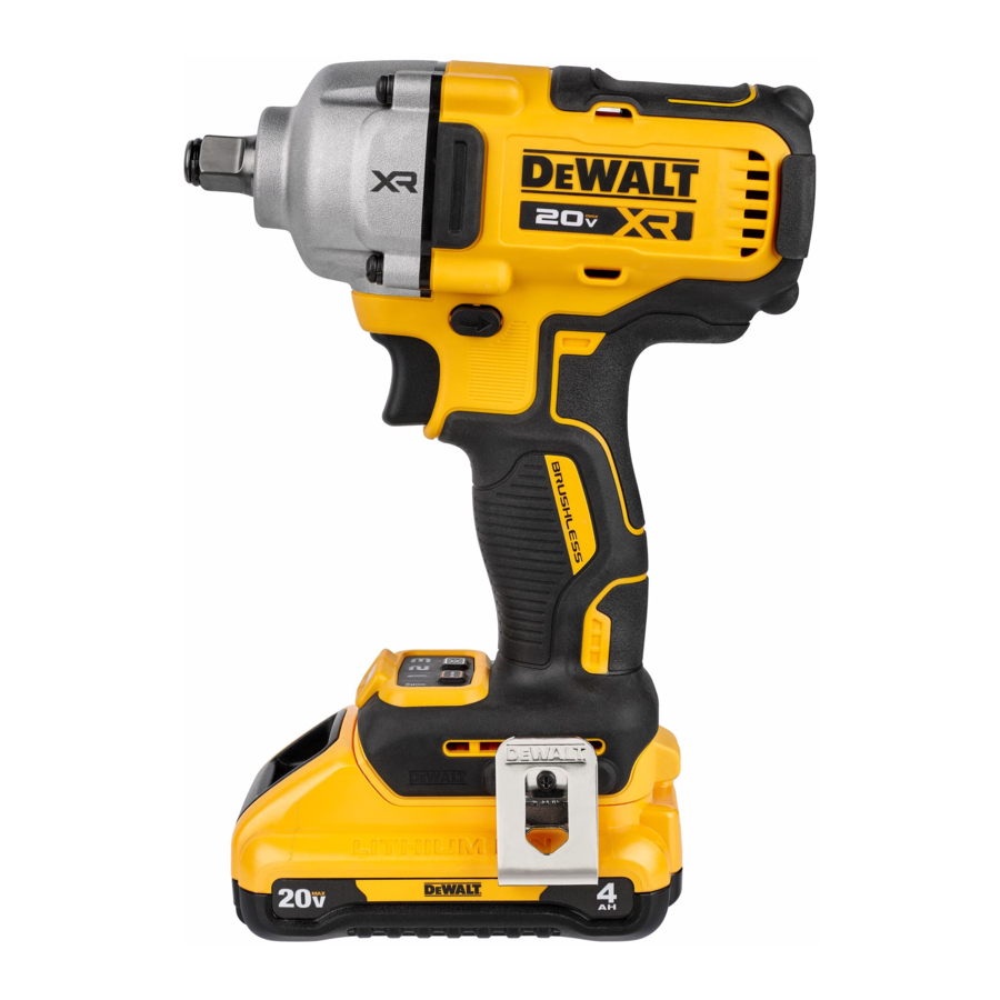
Description
See (Fig. A, B)
Never modify the power tool or any part of it. Damage or personal injury could result.

Fig. A
- Trigger switch
- Forward/reverse button
- Anvil
- Battery release button
- Battery pack
- Worklight
- Mode selector
- Belt hook
- Screw
- Main handle
Intended Use
These impact wrenches are designed for professional impact fastening applications. The impact function makes this tool particularly useful for driving fasteners in wood, metal and concrete.
DO NOT use under wet conditions or in the presence of flammable liquids or gases.
These impact wrenches are professional power tools.
DO NOT let children come into contact with the tool. Supervision is required when inexperienced operators use this tool.
- Young children and the infirm. This appliance is not intended for use by young children or infirm persons without supervision.
- This product is not intended for use by persons (including children) suffering from diminished physical, sensory or mental abilities; lack of experience, knowledge or skills unless they are supervised by a person responsible for their safety. Children should never be left alone with this product.
ASSEMBLY AND ADJUSTMENTS
To reduce the risk of serious personal injury, turn tool off and disconnect battery pack before making any adjustments or removing/ installing attachments or accessories. An accidental start‑up can cause injury.
Use only DeWALT battery packs and chargers.
Inserting and Removing the Battery Pack from the Tool
(Fig. B)
NOTE: Make sure your battery pack  is fully charged.
To Install the Battery Pack into the Tool Handle
- Align the battery pack
![]() with the rails inside the tool's handle (Fig. J).
with the rails inside the tool's handle (Fig. J). - Slide it into the handle until the battery pack is firmly seated in the tool and ensure that you hear the lock snap into place.
To Remove the Battery Pack from the Tool
- Press the release button
![]() and firmly pull the battery pack out of the tool handle.
and firmly pull the battery pack out of the tool handle. - Insert battery pack into the charger as described in the charger section of this manual.
 and firmly pull the battery pack out of the tool handle.
Fuel Gauge Battery Packs
(Fig. B)
Some DeWALT battery packs include a fuel gauge which consists of three green LED lights that indicate the level of charge remaining in the battery pack.
To actuate the fuel gauge, press and hold the fuel gauge button  . A combination of the three green LED lights will illuminate designating the level of charge left. When the level of charge in the battery is below the usable limit, the fuel gauge will not illuminate and the battery will need to be recharged.
NOTE: The fuel gauge is only an indication of the charge left on the battery pack. It does not indicate tool functionality and is subject to variation based on product components, temperature and end‑user application.
Belt Hook
To reduce the risk of serious personal injury, DO NOT suspend tool overhead or suspend objects from the belt hook. ONLY hang tool's belt hook from a work belt.
To reduce the risk of serious personal injury, ensure the screw holding the belt hook is secure.
To reduce the risk of personal injury or damage, DO NOT use the belt hook to hang the drill while using as a spotlight.

When attaching or replacing the belt hook, use only the screw  that is provided. Be sure to securely tighten the screw.
(Optional Accessory) (Fig. A)
The belt hook  can be be attached to either side of the tool using only the screw provided, to accommodate left‑ or right‑ handed users. If the hook is not desired at all, it can be removed from the tool.
To move belt hook, remove the screw that holds it in place then reassemble on the opposite side. Be sure to securely tighten the screw.
Variable Speed Trigger Switch
(Fig. A)
To turn the tool on, squeeze the trigger switch  . To turn the tool off, release the trigger switch. Your tool is equipped with a brake. The anvil will stop when the trigger switch is fully released. The variable speed switch enables you to select the best speed for a particular application. The more you squeeze the trigger, the faster the tool will operate. For maximum tool life, use variable speed only for starting holes or fasteners.
NOTE: Continuous use in variable speed range is not recommended. It may damage the switch and should be avoided.
Forward/Reverse Control Button
(Fig. A)
A forward/reverse control button  determines the direction of the tool and also serves as a lock‑off button.
To select forward rotation, release the trigger switch and depress the for ward/re verse control button on the right side of the tool.
To select reverse, release the trigger switch and depress the forward/reverse control button on the left side of the tool.
The centre position of the control button locks the tool in the off position. When changing the position of the control button, be sure the trigger is released.
NOTE: The first time the tool is run after changing the direction of rotation, you may hear a click on start up. This is normal and does not indicate a problem.
Worklight
(Fig. A, C)
The worklight  is activated when the variable speed trigger
  is depressed. Pressing the worklight switch
  repeatedly will cycle through low illumination, high illumination, and off.
NOTE: The worklight is for lighting the immediate work surface and is not intended to be used as a flashlight.

Mode Selector
(Fig. A, C)
Your tool is equipped with a mode selector  which allows you to select one of three speeds or Precision Wrench mode. Select the mode based on the maximum speed/torque needed and control the speed of the tool using the variable speed trigger switch .
Precision Wrench
(Fig. C)
In addition to low speed impacting modes, this tool features the Precision Wrench mode which grants the user greater control in both fastening and loosening applications. When set in forward, the tool will fasten at 2000 RPM until impact begins. The tool will then pause for 0.5 seconds before continuing to impact at a rate of 3250 IPM, providing the user with greater control and reducing the chance of overtightening or damaging material.
When set in reverse, the tool will impact at a normal speed and rate of 3250 IPM. Upon sensing that the fastener has broken free, the tool will cease to impact and will reduce speed to help prevent "run‑off" of loose hardware.
| Specifications | ||
| Mode | Application | RPM |
| Low Mode | Normal Impacting | 0–600 forward 0–2000 reverse |
| Medium Mode | Medium Impacting | 0–1200 forward 0–2000 reverse |
| High Mode | High Speed Impacting | 0–2000 forward 0–2000 reverse |
| Precision Wrench Mode | Precision Wrench | 0–2000 forward 0–2000 reverse |
Anvil
Use only impact accessories. Non‑impact accessories may break and cause a hazardous condition. Inspect accessory prior to use to ensure that it contains no cracks.
Inspect anvils, detent pins, and hog rings prior to use. Missing or damaged items should be replaced before use.
(Fig. A)
Place the switch in the locked off (centre) position or remove battery pack before changing accessories.

Fig. D
Anvil with Detent Pin
DCF892 (Fig. D)
To install an accessory on the anvil, align the hole in the side of the accessory with the detent pin  on the anvil
  . Press the accessory on until the detent pin engages in the hole. Depression of detent pin may be necessary to aid installation of accessory.
To remove an accessory, depress the detent pin through the hole and pull the accessory off.
Anvil With Hog Ring
DCF891 (Fig. D)
To install an accessory on the hog ring anvil, firmly push accessory onto the anvil . The hog ring  compresses to allow the accessory to slide on. After accessory is installed, the hog ring applies pressure to help provide accessory retention. To remove an accessory, grasp the accessory and firmly pull it off.
OPERATION
Instructions for Use
Always observe the safety instructions and applicable regulations.
To reduce the risk of serious personal injury, turn tool off and disconnect battery pack before making any adjustments or removing/installing attachments or accessories. An accidental start‑up can cause injury.
Proper Hand Position
To reduce the risk of serious personal injury, ALWAYS use proper hand position as shown.
To reduce the risk of serious personal injury, ALWAYS hold securely in anticipation of a sudden reaction.
Proper hand position requires one hand on the main handle  . (Fig. E)

Fig. E
Usage
Ensure fastener and/or system will withstand the level of torque generated by the tool. Excessive torque may cause breakage and possible personal injury.
(Fig. A)
- Place the accessory on the fastener head. Keep the tool pointed straight at the fastener.
- Press variable speed trigger switch
![]() to start operation. Release variable speed trigger switch to stop operation. Always check torque with a torque wrench, as the fastening torque is affected by many factors including the following:
to start operation. Release variable speed trigger switch to stop operation. Always check torque with a torque wrench, as the fastening torque is affected by many factors including the following: - Voltage: Low voltage, due to a nearly discharged battery, will reduce fastening torque.
- Accessory size: Failure to use the correct accessory size will cause a reduction in fastening torque.
- Bolt size: Larger bolt diameters generally require higher fastening torque. Fastening torque will also vary according to length, grade, and torque coefficient.
- Bolt: Ensure that all threads are free of rust and other debris to allow proper fastening torque.
- Material: The type of material and surface finish of the material will affect fastening torque.
- Fastening time: Longer fasten ing time results in increased fastening torque. Using a longer fastening time than recommended could cause the fasteners to be overstressed, stripped or damaged.
 to start operation. Release variable speed trigger switch to stop operation. Always check torque with a torque wrench, as the fastening torque is affected by many factors including the following:
 MAINTENANCE
Your power tool has been designed to operate over a long period of time with a minimum of maintenance. Continuous satisfactory operation depends upon proper tool care and regular cleaning.
To reduce the risk of serious personal injury, turn tool off and disconnect battery pack before making any adjustments or removing/installing attachments or accessories. An accidental start‑up can cause injury. The charger and battery pack are not serviceable.
Lubrication
Your power tool requires no additional lubrication.
Cleaning
Blow dirt and dust out of the main housing with dry air as often as dirt is seen collecting in and around the air vents. Wear approved eye protection and approved dust mask when performing this procedure.
Never use solvents or other harsh chemicals for cleaning the non‑metallic parts of the tool. These chemicals may weaken the materials used in these parts. Use a cloth dampened only with water and mild soap. Never let any liquid get inside the tool; never immerse any part of the tool into a liquid.
Optional Accessories
Since accessories, other than those offered by DeWALT, have not been tested with this product, use of such accessories with this tool could be hazardous. To reduce the risk of injury, only DeWALT recommended accessories should be used with this product. Consult your dealer for further information on the appropriate accessories.
Rechargeable Battery Pack
This long life battery pack must be recharged when it fails to produce sufficient power on jobs which were easily done before. At the end of its technical life, discard it with due care for our environment:
- Run the battery pack down completely, then remove it from the tool.
- Li‑Ion cells are recyclable. Take them to your dealer or a local recycling station. The collected battery packs will be recycled or disposed of properly.
After Service and Repair
DEWALT service centers are staffed with trained personnel to provide customers with efficient and reliable product service. We do not take any responsibility when you have repaired in unauthorized service center. You can refer to the leaflet of CONTACT CENTER LOCATOR in product package and contact us through hotline, website or social media to find the nearest DEWALT service center around you.
Documents / Resources
References
Download manual
Here you can download full pdf version of manual, it may contain additional safety instructions, warranty information, FCC rules, etc.
Advertisement


Need help?
Do you have a question about the XR DCF891 and is the answer not in the manual?
Questions and answers