DeWalt DCF880, DCF880H, DCF885C1 Manual
- Instruction manual (49 pages) ,
- Manual (2 pages) ,
- Original instructions manual (180 pages)
Advertisement
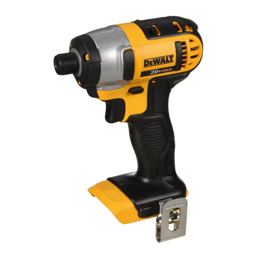
COMPONENT

Never modify the power tool or any part of it. Damage or personal injury could result.

- Trigger switch
- Forward/reverse button
- Chuck collar
- 1/4" (6.35 mm) hex quick-release chuck (DCF885)
- Battery release button
- Battery pack
- Worklight
- Belt hook (optional accessory)
- Screw
- Anvil
- Hog ring (DCF880H, DCF883)
- Detent pin (DCF880)
INTENDED USE
These heavy-duty impact wrench/drivers are designed for professional impact screwdriving applications. The impact function makes this tool particularly useful for driving fasteners in wood, metal and concrete. DO NOT use under wet conditions or in presence of flammable liquids or gases.
These heavy-duty impact wrench/drivers are professional power tools. DO NOT let children come into contact with the tool. Supervision is required when inexperienced operators use this tool.
Belt Hook (Optional Accessory) (Fig. 1)
To reduce the risk of serious personal injury, place the forward/reverse button in the lock-off position or turn tool off and disconnect battery pack before making any adjustments or removing/installing attachments or accessories.
To reduce the risk of serious personal injury, DO NOT suspend tool overhead or suspend objects from the belt hook. ONLY hang tool's belt hook from a work belt.
To reduce the risk of serious personal injury, ensure the screw holding the belt hook is secure.

When attaching or replacing the belt hook, use only the screw (I) that is provided. Be sure to securely tighten the screw.
The belt hook (H) can be be attached to either side of the tool using only the screw (I) provided, to accommodate left- or right- handed users. If the hook is not desired at all, it can be removed from the tool.
To move belt hook, remove the screw (I) that holds the belt hook in place then reassemble on the opposite side. Be sure to securely tighten the screw.
OPERATION
To reduce the risk of serious personal injury, place the forward/reverse button in the lock-off position or turn tool off and disconnect battery pack before making any adjustments or removing/installing attachments or accessories.
Installing and Removing the Battery Pack (Fig. 2)
NOTE: For best results, make sure your battery pack is fully charged.
To install the battery pack (F) into the tool handle, align the battery pack with the rails inside the tool's handle and slide it into the handle until the battery pack is firmly seated in the tool and ensure that it does not disengage.
To remove the battery pack from the tool, press the release button (E) and firmly pull the battery pack out of the tool handle. Insert it into the charger as described in the charger section of this manual.

FUEL GAUGE BATTERY PACKS (FIG. 4)

Some DeWALT battery packs include a fuel gauge which consists of three green LED lights that indicate the level of charge remaining in the battery pack.
The fuel gauge is an indication of approximate levels of charge remaining in the battery pack according to the following indicators:

To actuate the fuel gauge, press and hold the fuel gauge button (M). A combination of the three green LED lights will illuminate designating the level of charge left. When the level of charge in the battery is below the usable limit, the fuel gauge will not illuminate and the battery will need to be recharged.
NOTE: The fuel gauge is only an indication of the charge left on the battery pack. It does not indicate tool functionality and is subject to variation based on product components, temperature and end-user application.
For more information regarding fuel gauge battery packs, please contact call 1-800-4-DeWALT (1-800-433-9258) or visit our website www.dewalt.com.
Variable Speed Trigger Switch (Fig. 1)
To turn the tool on, squeeze the trigger switch (A). To turn the tool off, release the trigger switch. Your tool is equipped with a brake. The chuck will stop when the trigger switch is fully released. The variable speed switch enables you to select the best speed for a particular application. The more you squeeze the trigger, the faster the tool will operate. For maximum tool life, use variable speed only for starting holes or fasteners.
NOTE: Continuous use in variable speed range is not recommended. It may damage the switch and should be avoided.
Forward/Reverse Control Button (Fig. 1)
A forward/reverse control button (B) determines the direction of the tool and also serves as a lock-off button.
To select forward rotation, release the trigger switch and depress the forward/reverse control button on the right side of the tool.
To select reverse, release the trigger switch and depress the forward/reverse control button on the left side of the tool.
The center position of the control button locks the tool in the OFF position. When changing the position of the control button, be sure the trigger is released.
NOTE: The first time the tool is run after changing the direction of rotation, you may hear a click on start up. This is normal and does not indicate a problem.
Worklights (Fig. 1)

Do not stare into worklight. Serious eye injury could result.
There are three worklights (G) located around the chuck collar (C). The worklights are activated when the trigger switch is depressed, and will automatically turn off 20 seconds after the trigger switch is released. If the trigger switch remains depressed, the worklights will remain on.
NOTE: The worklights are for lighting the immediate work surface and are not intended to be used as a flashlight.
Quick-Release Chuck (Fig. 1, 5, 6)
DCF885
NOTE: The chuck accepts 1/4" (6.35 mm) hex accessories and 1" (25.4 mm) bit tips only. Place the forward/reverse button (B) in the lock-off (center) position or remove battery pack before changing accessories.
To install an accessory, fully insert the accessory. The accessory is locked into place (Fig. 5). To remove an accessory, pull the chuck collar (C) away from the front of the tool. Remove the accessory (Fig. 6).

Anvils
Use only impact accessories. Non-impact accessories may break and cause a hazardous condition. Inspect accessories prior to use to ensure that it cont ains no cracks.
Inspect anvils, detent pins and hog rings prior to use. Missing or damaged items should be replaced before use.
Place the switch in the locked off (center) position or remove battery pack before changing accessories.
ANVIL WITH HOG RING (FIG. 1, DCF880H, DCF883)
To install an accessory on the hog ring anvil, firmly push accessory onto the anvil (J). The hog ring (K) compresses to allow the accessory to slide on. After the accessory is installed, the hog ring applies pressure to help provide accessory retention. To remove an accessory, grasp the socket and firmly pull it off.
ANVIL WITH DETENT PIN (FIG. 1, DCF880)
To install an accessory on the anvil, align the hole in the side of the accessory with the detent pin (L) on the anvil (J). Press the accessory on until the detent pin engages in the hole. Depression of detent pin may be necessary to aid installation of the accessory.
To remove an accessory, depress the detent pin through the hole and pull the accessory off.
Usage
Your impact tool can generate the following maximum torque:
| Cat # | Ft.-Lbs. | In.-Lbs. | Nm |
| DCF880 | 150 | 1800 | 203 |
| DCF880H | 150 | 1800 | 203 |
| DCF883 | 130 | 1560 | 176 |
| DCF885 | 117 | 1400 | 155 |
Ensure fastener and/or system will withstand the level of torque generated by the tool. Excessive torque may cause breakage and possible personal injury.
- Place the socket on the fastener head. Keep the tool pointed straight at the fastener.
- Press switch to start operation. Release switch to stop operation. Always check torque with a torque wrench, as the fastening torque is affected by many factors including the following:
- Voltage: Low voltage, due to a nearly discharged battery, will reduce fastening torque.
- Accessory size: Failure to use the correct accessory size will cause a reduction in fastening torque.
- Bolt size: Larger bolt diameters generally require higher fastening torque. Fastening torque will also vary according to length, grade, and torque coefficient.
- Bolt: Ensure that all threads are free of rust and other debris to allow proper fastening torque.
- Material: The type of material and surface finish of the material will affect fastening torque.
- Fastening time: Longer fasten ing time results in increased fastening torque. Using a longer fastening time than recommended could cause the fasteners to be overstressed, stripped or damaged.
MAINTENANCE
To reduce the risk of serious personal injury, place the forward/reverse button in the lock-off position or turn tool off and disconnect battery pack before making any adjustments or removing/installing attachments or accessories.
Cleaning
Blow dirt and dust out of all air vents with clean, dry air at least once a week. To minimize the risk of eye injury, always wear ANSI Z87.1 approved eye protection when performing this.
Never use solvents or other harsh chemicals for cleaning the non-metallic parts of the tool. These chemicals may weaken the plastic materials used in these parts. Use a cloth dampened only with water and mild soap. Never let any liquid get inside the tool; never immerse any part of the tool into a liquid.
CHARGER CLEANING INSTRUCTIONS

Shock hazard. Disconnect the charger from the AC outlet before cleaning. Dirt and grease may be removed from the exterior of the charger using a cloth or soft non-metallic brush.
Do not use water or any cleaning solutions.
Accessories
Since accessories, other than those offered by DeWALT, have not been tested with this product, use of such accessories with this tool could be hazardous. To reduce the risk of injury, only DeWALT recommended accessories should be used with this product.
Recommended accessories for use with your tool are available at extra cost from your local service center. If you need any assistance in locating any accessory, please contact DeWALT Industrial Tool Co., 701 East Joppa Road, Towson, MD 21286, call 1-800-4-DeWALT (1-800433-9258) or visit our website: www.dewalt.com.
To reduce the risk of injury, use only DeWALT impact-ready accessories.
Use only impact sockets. Non-impact sockets may break and cause a hazardous condition. Inspect socke t prior to use to ensure that it contains no cracks.
Repairs
The charger and battery pack are not serviceable.
To assure product SAFETY and RELIABILITY, repairs, maintenance and adjustment (including brush inspection and replacement) should be performed by a DeWALT factory service center, a DeWALT authorized service center or other qualified service personnel. Always use identical replacement parts.
Register Online
Register your product now for:
- WARRANTY SERVICE: Registering your product will help you obtain more efficient warranty service in case there is a problem with your product.
- CONFIRMATION OF OWNERSHIP: In case of an insurance loss, such as fire, flood or theft, your registration of ownership will serve as your proof of purchase.
- FOR YOUR SAFETY: Registering your product will allow us to contact you in the unlikely event a safety notification is required under the Federal Consumer Safety Act.
Register online at www.dewalt.com/register.
SAFETY
Definitions: Safety Guidelines
The definitions below describe the level of severity for each signal word. Please read the manual and pay attention to these symbols.

Indicates an imminently hazardous situation which, if not avoided, will result in death or serious injury.
Indicates a potentially hazardous situation which, if not avoided, could result in death or serious injury.
Indicates a potentially hazardous situation which, if not avoided, may result in minor or moderate injury.
NOTICE: Indicates a practice not related to personal injury which, if not avoided, may result in property damage.
IF YOU HAVE ANY QUESTIONS OR COMMENTS ABOUT THIS OR ANY D e WALT TOOL, CALL US TOLL FREE AT: 1-800-4-D e WALT (1-800-433-9258).
To reduce the risk of injury, read the instruction manual.
General Power Tool Safety Warnings
Read all safety warnings and all instructions. Failure to follow the warnings and instructions may result in electric shock, fire and/or serious injury.
SAVE ALL WARNINGS AND INSTRUCTIONS FOR FUTURE REFERENCE
The term "power tool" in the warnings refers to your mains-operated (corded) power tool or battery-operated (cordless) power tool.
- WORK AREA SAFETY
- Keep work area clean and well lit. Cluttered or dark areas invite accidents.
- Do not operate power tools in explosive atmospheres, such as in the presence of flammable liquids, gases or dust. Power tools create sparks which may ignite the dust or fumes.
- Keep children and bystanders away while operating a power tool. Distractions can cause you to lose control.
- Remove any adjusting key or wrench before turning the power tool on. A wrench or a key left attached to a rotating part of the power tool may result in personal injury.
- Do not overreach. Keep proper footing and balance at all times. This enables better control of the power tool in unexpected situations.
- ELECTRICAL SAFETY
- Power tool plugs must match the outlet. Never modify the plug in any way. Do not use any adapter plugs with earthed (grounded) power tools. Unmodified plugs and matching outlets will reduce risk of electric shock.
- Avoid body contact with earthed or grounded surfaces such as pipes, radiators, ranges and refrigerators. There is an increased risk of electric shock if your body is earthed or grounded.
- Do not expose power tools to rain or wet conditions. Water entering a power tool will increase the risk of electric shock.
- Do not abuse the cord. Never use the cord for carrying, pulling or unplugging the power tool. Keep cord away from heat, oil, sharp edges or moving parts. Damaged or entangled cords increase the risk of electric shock.
- When operating a power tool outdoors, use an extension cord suitable for outdoor use. Use of a cord suitable for outdoor use reduces the risk of electric shock.
- If operating a power tool in a damp location is unavoidable, use a ground fault circuit interrupter (GFCI) protected supply. Use of a GFCI reduces the risk of electric shock.
- PERSONAL SAFETY
- Stay alert, watch what you are doing and use common sense when operating a power tool. Do not use a power tool while you are tired or under the influence of drugs, alcohol or medication. A moment of inattention while operating power tools may result in serious personal injury.
- Use personal protective equipment. Always wear eye protection. Protective equipment such as dust mask, non-skid safety shoes, hard hat, or hearing protection used for appropriate conditions will reduce personal injuries.
- Prevent unintentional starting. Ensure the switch is in the off position before connecting to power source and/or battery pack, picking up or carrying the tool. Carrying power tools with your finger on the switch or energizing power tools that have the switch on invites accidents.
- Dress properly. Do not wear loose clothing or jewelry. Keep your hair, clothing and gloves away from moving parts. Loose clothes, jewelry or long hair can be caught in moving parts.
- If devices are provided for the connection of dust extraction and collection facilities, ensure these are connected and properly used. Use of dust collection can reduce dust-related hazards.
- POWER TOOL USE AND CARE
- Do not force the power tool. Use the correct power tool for your application. The correct power tool will do the job better and safer at the rate for which it was designed.
- Do not use the power tool if the switch does not turn it on and off. Any power tool that cannot be controlled with the switch is dangerous and must be repaired.
- Disconnect the plug from the power source and/or the battery pack from the power tool before making any adjustments, changing accessories, or storing power tools. Such preventive safety measures reduce the risk of starting the power tool accidentally.
- Store idle power tools out of the reach of children and do not allow persons unfamiliar with the power tool or these instructions to operate the power tool. Power tools are dangerous in the hands of untrained users.
- Maintain power tools. Check for misalignment or binding of moving parts, breakage of parts and any other condition that may affect the power tool's operation. If damaged, have the power tool repaired before use. Many accidents are caused by poorly maintained power tools.
- Keep cutting tools sharp and clean. Properly maintained cutting tools with sharp cutting edges are less likely to bind and are easier to control.
- Use the power tool, accessories and tool bits, etc. in accordance with these instructions, taking into account the working conditions and the work to be performed. Use of the power tool for operations different from those intended could result in a hazardous situation.
- BATTERY TOOL USE AND CARE
- Recharge only with the charger specified by the manufacturer. A charger that is suitable for one type of battery pack may create a risk of fire when used with another battery pack.
- Use power tools only with specifically designated battery packs. Use of any other battery packs may create a risk of injury and fire.
- When battery pack is not in use, keep it away from other metal objects like paper clips, coins, keys, nails, screws, or other small metal objects that can make a connection from one terminal to another. Shorting the battery terminals together may cause burns or a fire.
- Under abusive conditions, liquid may be ejected from the battery; avoid contact. If contact accidentally occurs, flush with water. If liquid contacts eyes, additionally seek medical help. Liquid ejected from the battery may cause irritation or burns.
- SERVICE
- Have your power tool serviced by a qualified repair person using only identical replacement parts. This will ensure that the safety of the power tool is maintained.
Additional Specific Safety Rules
- Hold power tool by insulated gripping surfaces when performing an operation where the fastener may contact hidden wiring. Fasteners contacting a "live" wire may make exposed metal parts of the power tool "live" and could give the operator an electric shock.
- Use clamps or other practical way to secure and support the workpiece to a stable platform. Holding the work by hand or against your body is unstable and may lead to loss of control.
- Wear safety goggles or other eye protection. Hammering and drilling operations cause chips to fly. Flying particles can cause permanent eye damage.
- Accessories and tools get hot during operation. Wear gloves when touching them.
- Air vents often cover moving parts and should be avoided. Loose clothes, jewelry or long hair can be caught in moving parts.
- Do not operate this tool for long periods of time. Vibration caused by tool action may be harmful to your hands and arms. Use gloves to provide extra cushion and limit exposure by taking frequent rest periods.
ALWAYS use safety glasses. Everyday eyeglasses are NOT safety glasses. Also use face or dust mask if cutting operation is dusty. ALWAYS WEAR CERTIFIED SAFETY EQUIPMENT:
- ANSI Z87.1 eye protection (CAN/CSA Z94.3),
- ANSI S12.6 (S3.19) hearing protection,
- NIOSH/OSHA/MSHA respiratory protection.
Some dust created by power sanding, sawing, grinding, drilling, and other construction activities contains chemicals known to the State of California to cause cancer, birth defects or other reproductive harm. Some examples of these chemicals are:
- lead from lead-based paints,
- crystalline silica from bricks and cement and other masonry products, and
- arsenic and chromium from chemically-treated lumber.
Your risk from these exposures varies, depending on how often you do this type of work. To reduce your exposure to these chemicals: work in a well ventilated area, and work with approved safety equipment, such as those dust masks that are specially designed to filter out microscopic particles. - Avoid prolonged contact with dust from power sanding, sawing, grinding, drilling, and other construction activities. Wear protective clothing and wash exposed areas with soap and water. Allowing dust to get into your mouth, eyes, or lay on the skin may promote absorption of harmful chemicals.
Use of this tool can generate and/or disburse dust, which may cause serious and permanent respiratory or other injury. Always use NIOSH/OSHA approved respiratory protection appropriate for the dust exposure. Direct particles away from face and body.
ALWAYS wear proper personal hearing protection that conforms to ANSI S12.6 (S3.19) during use. Under some conditions and duration of use, noise from this product may contribute to hearing loss.
When not in use, place tool on its side on a stable surface where it will not cause a tripping or falling hazard. Some tools with large battery packs will stand upright on the battery pack but may be easily knocked over.
- The label on your tool may include the following symbols. The symbols and their definitions are as follows:
![]()

Important Safety Instructions for All Battery Packs
When ordering replacement battery packs, be sure to include the catalog number and voltage. Consult the chart at the end of this manual for compatibility of chargers and battery packs. The battery pack is not fully charged out of the carton. Before using the battery pack and charger, read the safety instructions below and then follow charging procedures outlined.
READ ALL INSTRUCTIONS
- Do not charge or use the battery pack in explosive atmospheres, such as in the presence of flammable liquids, gases or dust. Inserting or removing the battery pack from the charger may ignite the dust or fumes.
- NEVER force the battery pack into the charger. DO NOT modify the battery pack in any way to fit into a non-compatible charger as battery pack may rupture causing serious personal injury. Consult the chart at the end of this manual for compatibility of batteries and chargers.
- Charge the battery packs only in designated DeWALT chargers.
- DO NOT splash or immerse in water or other liquids.
- Do not store or use the tool and battery pack in locations where the temperature may reach or exceed 104°F (40°C) (such as outside sheds or metal buildings in summer). For best life store battery packs in a cool, dry location.
NOTE: Do not store the battery packs in a tool with the trigger switch locked on. Never tape the trigger switch in the ON position.
Fire hazard. Never attempt to open the battery pack for any reason. If the battery pack case is cracked or damaged, do not insert into the charger. Do not crush, drop or damage the battery pack. Do not use a battery pack or charger that has received a sharp blow, been dropped, run over or damaged in any way (e.g., pierced with a nail, hit with a hammer, stepped on). Damaged battery packs should be returned to the service center for recycling.
Fire hazard. Do not store or carry the battery pack so that metal objects can contact exposed battery terminals. For example, do not place the battery pack in aprons, pockets, tool boxes, product kit boxes, drawers, etc., with loose nails, screws, keys, etc. Transporting batteries can possibly cause fires if the battery terminals inadvertently come in contact with conductive materials such as keys, coins, hand tools and the like. The US Department of Transportation Hazardous Material Regulations (HMR) actually prohibit transporting batteries in commerce or on airplanes (e.g., packed in suitcases and carryon luggage) UNLESS they are properly protected from short circuits. So when transporting individual battery packs, make sure that the battery terminals are protected and well insulated from materials that could contact them and cause a short circuit.
SPECIFIC SAFETY INSTRUCTIONS FOR LITHIUM ION (Li-Ion)
- Do not incinerate the battery pack even if it is severely damaged or is completely worn out. The battery pack can explode in a fire. Toxic fumes and materials are created when lithium ion battery packs are burned.
- If battery contents come into contact with the skin, immediately wash area with mild soap and water. If battery liquid gets into the eye, rinse water over the open eye for 15 minutes or until irritation ceases. If medical attention is needed, the battery electrolyte is composed of a mixture of liquid organic carbonates and lithium salts.
- Contents of opened battery cells may cause respiratory irritation. Provide fresh air. If symptoms persist, seek medical attention.
Burn hazard. Battery liquid may be flammable if exposed to spark or flame.
Important Safety Instructions for All Battery Chargers
SAVE THESE INSTRUCTIONS: This manual contains important safety and operating instructions for battery chargers.
- Before using the charger, read all instructions and cautionary markings on the charger, battery pack and product using the battery pack.
Shock hazard. Do not allow any liquid to get inside the charger. Electric shock may result.
Burn hazard. To reduce the risk of injury, charge only DeWALT rechargeable battery packs. Other types of batteries may overheat and burst resulting in personal injury and property damage.
NOTICE: Under certain conditions, with the charger plugged into the power supply, the charger can be shorted by foreign material. Foreign materials of a conductive nature, such as, but not limited to, grinding dust, metal chips, steel wool, aluminum foil or any buildup of metallic particles should be kept away from the charger cavities. Always unplug the charger from the power supply when there is no battery pack in the cavity. Unplug the charger before attempting to clean.
- DO NOT attempt to charge the battery pack with any chargers other than the ones in this manual. The charger and battery pack are specifically designed to work together.
- These chargers are not intended for any uses other than charging DeWALT rechargeable batteries. Any other uses may result in risk of fire, electric shock or electrocution.
- Do not expose the charger to rain or snow.
- Pull by the plug rather than the cord when disconnecting the charger. This will reduce the risk of damage to the electric plug and cord.
- Make sure that the cord is located so that it will not be stepped on, tripped over or otherwise subjected to damage or stress.
- Do not use an extension cord unless it is absolutely necessary. Use of improper extension cord could result in risk of fire, electric shock or electrocution.
- When operating a charger outdoors, always provide a dry location and use an extension cord suitable for outdoor use. Use of a cord suitable for outdoor use reduces the risk of electric shock.
- An extension cord must have adequate wire size (AWG or American Wire Gauge) for safety. The smaller the gauge number of the wire, the greater the capacity of the cable, that is, 16 gauge has more capacity than 18 gauge. An undersized cord will cause a drop in line voltage resulting in loss of power and overheating. When using more than one extension to make up the total length, be sure each individual extension contains at least the minimum wire size. The following table shows the correct size to use depending on cord length and nameplate ampere rating. If in doubt, use the next heavier gauge. The lower the gauge number, the heavier the cord.
| Minimum Gauge for Cord Sets | ||||||
| Ampere Rating | Volts | Total Length of Cord in Feet (meters) | ||||
| 120V | 25 (7.6) | 50 (15.2) | 100 (30.5) | 150 (45.7) | ||
| 240V | 50 (15.2) | 100 (30.5) | 200 (61.0) | 300 (91.4) | ||
| More Than | Not More Than | AWG | ||||
| 0 | 6 | 18 | 16 | 16 | 14 | |
| 6 | 10 | 18 | 16 | 14 | 12 | |
| 10 | 12 | 16 | 16 | 14 | 12 | |
| 12 | 16 | 14 | 12 | Not Recommended | ||
- Do not place any object on top of the charger or place the charger on a soft surface that might block the ventilation slots and result in excessive internal heat. Place the charger in a position away from any heat source. The charger is ventilated through slots in the top and the bottom of the housing.
- Do not operate the charger with a damaged cord or plug.
- Do not operate the charger if it has received a sharp blow, been dropped or otherwise damaged in any way. Take it to an authorized service center.
- Do not disassemble the charger; take it to an authorized service center when service or repair is required. Incorrect reassembly may result in a risk of electric shock, electrocution or fire.
- Disconnect the charger from the outlet before attempting any cleaning. This will reduce the risk of electric shock. Removing the battery pack will not reduce this risk.
- NEVER attempt to connect 2 chargers together.
- The charger is designed to operate on standard 120 V household electrical power. Do not attempt to use it on any other voltage. This does not apply to the vehicular charger.
Chargers
Your tool uses a DeWALT charger. Be sure to read all safety instructions before using your charger. Consult the chart at the end of this manual for compatibility of chargers and battery packs.
Charging Procedure (Fig. 3)

- Plug the charger into an appropriate outlet before inserting the battery pack.
- Insert the battery pack (F) into the charger, as shown in Figure 3, making sure the pack is fully seated in charger. The red (charging) light will blink continuously, indicating that the charging process has started.
- The completion of charge will be indicated by the red light remaining ON continuously. The pack is fully charged and may be used at this time or left in the charger.
Indicator Light Operation

Charge Indicators
This charger is designed to detect certain problems that can arise. Problems are indicated by the red light flashing at a fast rate. If this occurs, re-insert the battery pack into the charger. If the problem persists, try a different battery pack to determine if the charger is working properly. If the new pack charges correctly, then the original pack is defective and should be returned to a service center or other collection site for recycling. If the new battery pack elicits the same trouble indication as the original, have the charger and the battery pack tested at an authorized service center.
HOT/COLD DELAY
DCB101, DCB102, DCB103
These chargers have a hot/cold delay feature. When the charger detects a battery that is too hot or too cold, it automatically starts a delay, suspending charging. The red light flashes long, then short while in the hot/cold delay mode.
Once the battery has reached an optimum temperature, the charger will automatically resume the charging procedure. This feature ensures maximum battery life.
DCB107, DCB112, DCB113, DCB115
These chargers have a hot/cold delay feature. When the charger detects a battery that is too hot or too cold, it automatically starts a delay, suspending charging. The red light will continue to blink, but a yellow indicator light will be illuminated during this suspension.
Once the battery has reached an optimum temperature, the yellow light will turn off and the charger will automatically resume the charging procedure. This feature ensures maximum battery life.
LEAVING THE BATTERY PACK IN THE CHARGER
The charger and battery pack can be left connected with the charge indicator showing Pack Charged.
WEAK BATTERY PACKS: Weak batteries will continue to function but should not be expected to perform as much work.
FAULTY BATTERY PACKS DCB101, DCB102, DCB103
These chargers will not charge a faulty battery pack. The charger will indicate faulty battery pack by refusing to light or by displaying problem pack or charger.
NOTE: This could also mean a problem with a charger.
DCB107, DCB112, DCB113, DCB115
These chargers will not charge a faulty battery pack. The charger will indicate faulty battery pack by refusing to light.
NOTE: This could also mean a problem with a charger.
Wall Mounting
DCB107, DCB112, DCB113, DCB115
These chargers are designed to be wall mountable or to sit upright on a table or work surface.
If wall mounting, locate the charger within reach of an electrical outlet. Mount the charger securely using drywall screws at least 1" (25.4 mm) long, screwed into wood to an optimal depth leaving approximately 7/32" (5.5 mm) of the screw exposed.
Important Charging Notes
- Longest life and best performance can be obtained if the battery pack is charged when the air temperature is between 65°F and 75°F (18 ° – 24°C). DO NOT charge the battery pack in an air temperature below +40°F (+4.5°C), or above +104°F (+40°C). This is important and will prevent serious damage to the battery pack.
- The charger and battery pack may become warm to the touch while charging. This is a normal condition, and does not indicate a problem. To facilitate the cooling of the battery pack after use, avoid placing the charger or battery pack in a warm environment such as in a metal shed or an uninsulated trailer.
- A cold battery pack will charge at about half the rate of a warm battery pack. The battery pack will charge at that slower rate throughout the entire charging cycle and will not return to maximum charge rate even if the battery pack warms.
- If the battery pack does not charge properly:
- Check operation of receptacle by plugging in a lamp or other appliance;
- Check to see if receptacle is connected to a light switch which turns power off when you turn out the lights;
- Move the charger and battery pack to a location where the surrounding air temperature is approximately 65°F – 75°F (18 ° – 24°C);
- If charging problems persist, take the tool, battery pack and charger to your local service center.
- The battery pack should be recharged when it fails to produce sufficient power on jobs which were easily done previously. DO NOT CONTINUE to use under these conditions. Follow the charging procedure. You may also charge a partially used pack whenever you desire with no adverse effect on the battery pack.
- Foreign materials of a conductive nature such as, but not limited to, grinding dust, metal chips, steel wool, aluminum foil, or any buildup of metallic particles should be kept away from charger cavities. Always unplug the charger from the power supply when there is no battery pack in the cavity. Unplug the charger before attempting to clean.
- Do not freeze or immerse the charger in water or any other liquid.
Shock hazard. Don't allow any liquid to get inside the charger. Electric shock may result.
Burn hazard. Do not submerge the battery pack in any liquid or allow any liquid to enter the battery pack. Never attempt to open the battery pack for any reason. If the plastic housing of the battery pack breaks or cracks, return to a service center for recycling.
Storage Recommendations
- The best storage place is one that is cool and dry, away from direct sunlight and excess heat or cold.
- For long storage, it is recommended to store a fully charged battery pack in a cool dry place out of the charger for optimal results.
NOTE: Battery packs should not be stored completely depleted of charge. The battery pack will need to be recharged before use.
SAVE THESE INSTRUCTIONS FOR FUTURE USE
Documents / ResourcesDownload manual
Here you can download full pdf version of manual, it may contain additional safety instructions, warranty information, FCC rules, etc.
Advertisement


Need help?
Do you have a question about the DCF880 and is the answer not in the manual?
Questions and answers