Advertisement
Table of Contents
- 1 Safety Rules
- 2 Additional Safety Rules for Drill Presses
- 3 Power Connections
- 4 Extension Cords
- 5 Motor Specifications
- 6 Grounding Instructions
- 7 Locking Switch in the "Off" Position
- 8 Table Adjustments
- 9 Spindle Speeds
- 10 Changing Speeds and Adjusting Belt Tension
- 11 Adjusting Spindle Return Spring
- 12 Operation
- 13 Installing and Removing Drill Bits
- 14 Correct Drilling Speeds
- 15 Drilling Metal
- Download this manual
Advertisement
Table of Contents

Related Manuals for Delta 900585


Summary of Contents for Delta 900585
- Page 1 8" Drill Press (Model 11-900) PART NO. 900585 (011) Copyright © 2001 Delta Machinery To learn more about DELTA MACHINERY ESPAÑOL: PÁGINA 17 visit our website at: www.deltamachinery.com. For Parts, Service, Warranty or other Assistance, 1-800-223-7278 ( 1-800-463-3582). please call...
-
Page 2: Safety Rules
If you have any questions relative to a particular application, DO NOT use the machine until you have first contacted Delta to determine if it can or should be performed on the product. -
Page 3: Additional Safety Rules For Drill Presses
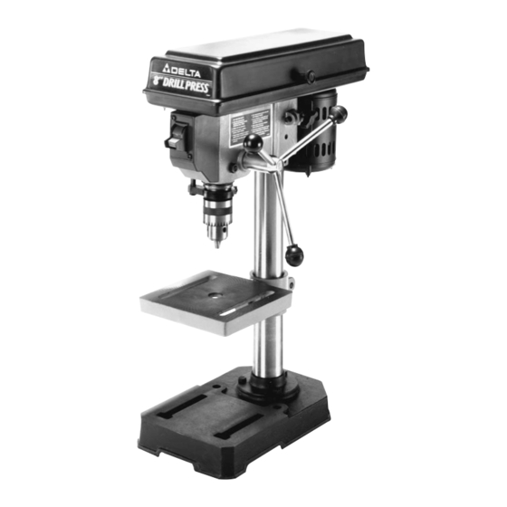
4. NEVER turn the drill press “on” before clearing the table of all objects (tools, scrap pieces, etc.). 5. NEVER start the drill press with the drill bit or cutting tool in contact with the workpiece. 6. USE ONLY drill bits, cutters, sanding drums and other accessories with 1/2"... - Page 4 Your drill press is shipped complete in one container. Carefully unpack the drill press and all loose items from the container. Figure 2 illustrates the drill press and all loose items supplied with the machine. WARNING: FOR YOUR OWN SAFETY, DO NOT CONNECT THE DRILL PRESS TO THE POWER SOURCE UNTIL THE MACHINE IS COMPLETELY ASSEMBLED AND YOU HAVE READ AND UNDERSTOOD THE ENTIRE INSTRUCTION MANUAL.
- Page 5 Remove the protective coating from the machined surfaces of the drill press and all loose items. This coating may be removed with a soft cloth moistened with kerosene. DO NOT use acetone, gasoline, or lacquer thinner for this purpose. ASSEMBLING THE DRILL PRESS 1.
- Page 6 4. Place the drill press head (F) Fig. 7, onto the column (A) as far as it will go. Align head to table and base and tighten the two head locking screws (G) with wrench supplied. 5. Thread the three pinion shaft handles (H) Fig. 8, into the three holes located in the pinion shaft (J) as shown.
-
Page 7: Power Connections
SUPPORTING SURFACE If during operation there is any tendency for the drill press to tip over, slide or walk on the supporting surface, the drill press base must be secured to the supporting surface with fasteners through the two holes (A) Fig. 14, located in the drill press base. -
Page 8: Motor Specifications
MOTOR SPECIFICATIONS Your drill press is wired for 110-120 volt, 60 HZ alternating current. Before connecting the machine to the power source, make sure the switch is in the “OFF” position. The motor provides a no-load speed of 1725 RPM. -
Page 9: Locking Switch In The "Off" Position
STARTING AND STOPPING DRILL PRESS The switch (A) Fig. 18, is located on the front of the drill press head. To turn the drill press “ON” move the switch to the up position. To turn the drill press “OFF” move the switch to the down position. -
Page 10: Spindle Speeds
SPINDLE SPEEDS Five spindle speeds of 620, 1100, 1720, 2340 and 3100 RPM are available with your drill press. The highest speed is obtained when the belt is on the largest step of the motor pulley and the smallest step of the spindle pulley, as shown in Fig. -
Page 11: Changing Speeds And Adjusting Belt Tension
3. Release belt tension by loosening tension lock knob (B) Fig. 27, and pivoting the motor (D) toward the front of the drill press. 4. While holding the motor toward the front of the drill press head, position the belt (C) on the desired steps of the motor and spindle pulleys, as shown in Fig. 27. -
Page 12: Adjusting Spindle Return Spring
(E) against the lower stop nut (C). Fig. 28 2. Drill a test hole to check the adjustment and readjust if necessary. All holes will be drilled to the depth indicated by the setting of the lower stop nut (C) Fig. 28, as it contacts the depth stop (D) when the spindle is lowered. -
Page 13: Operation
OPERATION Your drill press is to be used with drill bits of 1/2" or less in diameter. The following will give the inexperienced operator a start on common drill press operations. Use scrap material for practice to get a feel of the machine before attempting regular work. -
Page 14: Drilling Metal
Do not use hand bits which have a screw tip; at drill press speeds, they turn into the wood so rapidly as to lift the work off the table and whirl it. - Page 15 NOTES...
- Page 16 All Delta Machines and accessories are manufactured to high quality standards and are serviced by a network of Porter-Cable/Delta Factory Service Centers and Delta Authorized Service Stations. To obtain additional information regarding your Delta quality product or to obtain parts, service, warranty assistance, or the location of the nearest service outlet, please call 1-800-223-7278 (In Canada call 1-800-463-3582).
Need help?
Do you have a question about the 900585 and is the answer not in the manual?
Questions and answers