Table of Contents
Advertisement
Quick Links
Advertisement
Table of Contents

Related Manuals for BK Precision DAQ3120


Summary of Contents for BK Precision DAQ3120
-
Page 2: Table Of Contents
Contents Compliance Information EMC ................8 IEC Measurement Category &... - Page 3 5.6.1 Initiating Scan Mode ............5.6.2 Scan Course Execution .
- Page 4 6.6.1.3 F1 (Auto Zero) Key – Enable Auto Zero (DCV Only) 6.6.2 DC and AC Measurements 2/2 Page ..........6.6.2.1 F1 (Auto Zero) Key –...
- Page 5 10.1.5 Knob Mode ..............101 10.2 Histogram Display .
- Page 6 14.1 Capture Function ............. . . 123 14.2 Scan Data Function .
- Page 7 18 Remote Interface 18.1 Configure Interface ............. 137 18.1.1 Return to Local Control Mode .
-
Page 8: Emc
Compliance Information 1.1 EMC EC Declaration of Conformity - EMC Compliance was demonstrated to the following specifications listed in the Official Journal of the European Communities: EMC Directive 2014/30/EU. EN IEC 61326-1:2021 Electrical equipment for measurement, control and laboratory use. EMC requirements - General requirements EN IEC 61326-2-2:2021Electrical equipment for measurement, control and laboratory use - EMC requirements - Part 2-2... -
Page 9: Iec Measurement Category & Pollution Degree Definitions
Compliance Information 1.2 IEC Measurement Category & Pollution Degree Definitions Measurement Category (CAT) - classification of testing and measuring circuits according to the types of mains circuits to which they are intended to be connected. Measurement Category other than II, III, or IV : circuits that are not directly connected to the mains supply. -
Page 10: Product End-Of-Life Handling
Compliance Information 1.3 Product End-of-Life Handling The equipment may contain substances that could be harmful to the environment or human health if improperly handled at the product’s end of life. To avoid release of such substances into the environment and to reduce the use of natural resources, we encourage you to recycle this product to an appropriate system that will ensure that most of the materials are reused or recycled appropriately. - Page 11 Compliance Information Symbols - HIGH VOLTAGE - possibility of electric shock. WARNING – Statements or instructions that must be consulted in CAUTION order to find out the nature of the potential hazard and any actions which must be taken. On (Supply). This is the AC mains connect/disconnect switch on the front of the instrument.
-
Page 12: Electrical Power
Safety Notices The following safety precautions apply to both operating and maintenance personnel and must be followed during all phases of operation, service, and repair of this instrument. Before applying power to this instrument: • Read and understand the safety and operational information in this manual. •... - Page 13 Safety Notices Ground the Instrument To minimize shock hazard, the instrument chassis and cabinet must be connected to an electrical safety ground. This instrument is grounded through the ground conductor of the supplied, three- conductor AC line power cable. The power cable must be plugged into an approved three-conductor electrical outlet.
-
Page 14: Environmental Conditions
Safety Notices Environmental Conditions This instrument is intended to be used in an indoor pollution degree 2 environment. The operating temperature range is 0 C to 40 C and 20% to 80% relative humidity, with no condensation allowed. ∘ ∘ Measurements made by this instrument may be outside specifications if the instrument is used in non- office-type environments. - Page 15 Safety Notices Do not operate instrument if damaged If the instrument is damaged, appears to be damaged, or if any liquid, chemical, or other material gets on or inside the instrument, remove the instrument’s power cord, remove the instrument from service, label it as not to be operated, and return the instrument to B&K Precision for repair.
- Page 16 Safety Notices Do not touch live circuits Instrument covers must not be removed by operating personnel. Component replacement and internal adjustments must be made by qualified service-trained maintenance personnel who are aware of the hazards involved when the instrument’s covers and shields are removed.
- Page 17 Safety Notices Servicing Do not substitute parts that are not approved by B&K Precision or modify this instrument. Return the instrument to B&K Precision for service and repair to ensure that safety and performance features are maintained. Fuse replacement must be done by qualified service-trained maintenance personnel who are aware of the instrument’s fuse requirements and safe replacement procedures.
-
Page 18: Introduction
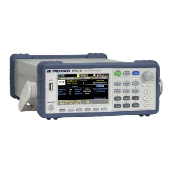
Introduction The DAQ3120 benchtop data acquisition system combines a 6½-digit DMM with a modular design for versatile measurement and analysis. The 3-slot mainframe and built-in DMM offer flexibility and high-resolution (0.0035% basic DCV accuracy). It measures 14 signal types including; temperature, voltage, current, resistance, frequency, capacitance, and strain. -
Page 19: Features
Introduction 3.2 Features 1. 3-slot base unit with built-in 6 ½ digit DMM 2. Basic 0.0035% DCV accuracy 3. 5 modules available to customize with • DM300 20-CH Solid-State Mux • DM301 20-CH Mux with 2 Current CH • DM303 40-CH Single-ended Mux •... -
Page 20: Dimensions
Introduction 3.3 Dimensions The MPS mainframe dimensions are approximately: 266.9 mm (10.5 in) x 107 (4.2 in) x 357.8 mm (14.1 in)(W x H x D) Configuration Dimensions (W x H x D) Weight Rack 8.7 x 3.5 x 13.7 in (220 x 88 x 348.6 mm) 9.92 lbs (4.5 kg) Bench 10.5 x 4.2 x 14.1 in (266.9 x 107 x 357.8 mm) -
Page 21: Front Panel
Introduction 3.4 Front Panel Figure 3.2 Front Panel Item Name Description USB Host Port USB port used to connect flash drives. Display Visual presentation of the device function and measurements. Switch the instrument between normal operation mode and Power Button screen-saver mode. -
Page 22: Rear Panel
Introduction 3.5 Rear Panel Figure 3.3 Rear Panel Item Name Description Module Slots Three plug-in module installation slots. GPIB Interface GPIB interface connector. AC power input Houses the IEC 320 connector and the fuse. & fuse box Digital I/O Send or receive a signal to or from an external device. LAN interface connector Left LED indicates activity. -
Page 23: Model Descriptions
Introduction 3.6 Model Descriptions Measurement Modules DM300 DM301 DM303 DM304 DM309 20 + 2 current 40 single-ended 32 cross-points 8 + 2 current No. of Channels 2-wire solid-state 2-wire armature Single armature 2-wire armature 2-wire armature Switching Speed (ch/s) 120 V 300 V 300 V 300 V... -
Page 24: Preliminary Information
Installation Preliminary Information ............Module Slot Cover Removing . -
Page 25: Observe Environmental Conditions
Installation Observe Environmental Conditions The environmental conditions of the instrument are documented under Environmental Characteristics. The unit should only be operated indoors in a controlled environment. The dimensions of your instrument as well as an outline diagram are also documented under Specifications. A fan cools the power system by drawing air through the sides and exhausting it out the back. -
Page 26: Module Slot Cover Removing
Figure 4.1 Unleash Cover Step 2. Use two fingers to grip the curved areas on both the right and left sides of the slot cover and gently pull outward to remove the slot cover from the DAQ3120 unit. Figure 4.2 Remove Cover Press and shake the curved area from either the right or left side alternately when it is difficult to release the inner hook on one side. -
Page 27: Module Installation
Follow the steps below for how to connect a wire to a module and install it into a slot on the rear panel of the DAQ3120 unit. Step 1. Use a Phillips-head screwdriver to loosen the screw from the top of the module, then remove the upper cover from the module. - Page 28 Step 3. Restore the upper cover back onto the module and fasten the screw using a Phillips-head screwdriver. Figure 4.5 Screw Module Cover Step 4. Insert the module into one of the module slots on the rear panel of the DAQ3120 unit. Figure 4.6 Insert Module...
-
Page 29: Module Revomal
Installation 4.4 Module Revomal Follow the step below for how to uninstall a module from a slot on the rear panel of the DAQ3120 unit. 4.4.1 Step Step 1. First, push inward the clip at the rear-left corner of the module, then pull the module out from a slot on the rear panel of the DAQ3120 unit. -
Page 30: Fuse Replacement
Installation 4.5 Fuse Replacement The fuse is accessible through the rear panel beneath the IEC 320 connector. Table 4.1shows the fuse requirements. Model Fuse Specification MPS1000 T10AL 250V MPS1001 T10AL 250V Table 4.1 Fuse Specification No power should be applied to the instrument while replacing the fuse. -
Page 31: Operation Menus
Operation Menus The DAQ3120 Series offers three operation menus; Home, Monitor, and Scan. Home Menu .............. -
Page 32: Home Menu
Operation Menus 5.1 Home Menu Press and hold the Home key on the front panel for one second to access the Home menu, where various basic settings are displayed. Status Modules Info Sweep Info Settings Channel Info Info Softkey functions Figure 5.1 Home Menu Section Description... -
Page 33: Alarm Mode Settings (F1 - Alarmout Key)
DMM Enabled: The internal DMM is active. • DMM Disabled: DAQ3120 functions as a switching hub, routing DUT signals to an external DMM for measurement. When disabled, the DMM icon appears in the status bar, and measurement settings for each channel become limited. -
Page 34: Strain Offset Configuration (F5 - Strain Key)
Operation Menus 5.1.5 Strain Offset Configuration (F5 - Strain Key) When measuring strain, Strain Offset can be applied for compensation. • Select: Opens a list of strain-measurement channels. Use the knob or arrow keys to navigate and press Select or SelectAll to confirm. Use Cancel or ClearAll to deselect. Press OK to confirm or Exit to leave without saving. -
Page 35: Monitor Mode
Operation Menus 5.2 Monitor Mode Press the Monitor key on the front panel to activate the monitor function and view real-time measurements for a selected channel. If Scan Mode is running simultaneously, the displayed reading updates only when the selected channel is scanned during a sweep. Press the Monitor key again to exit monitor mode. -
Page 36: Number Display
Operation Menus 5.3 Number Display Displays measured readings in numerical format. The maximum digit count depends on the Digit configuration. • Restart: When STAT in MathDisp is enabled, pressing Restart remeasures STAT values. 5.4 Bar Meter Display Shows a bar meter in the lower section with a numerical display on top. The number display digit limit depends on the Digit configuration. -
Page 37: Number Display (F1 - Display Key)
Operation Menus 5.5.1 Number Display (F1 - Display Key) • Number Mode: Displays readings in numerical format. The maximum digit count is determined by the Digit configuration. • Restart: Functions like the Restart key in Trend Chart and Histogram displays. When STAT in MathDisp is enabled, pressing Restart remeasures STAT values. -
Page 38: Histogram Display (F1 - Display Key)
Operation Menus 5.5.4 Histogram Display (F1 - Display Key) • Histogram Mode: The screen shows a Histogram Display in the lower section along with a Number Display on top. The maximum digit count follows the Digit configuration. • Bins: Displays up to 100 bins, representing measured counts. –... -
Page 39: Scan Mode
5.6 Scan Mode 5.6.1 Initiating Scan Mode Press the Scan key on the front panel to start the scan function. During a scan course, the DAQ3120 scans all available channels with pre-configured measurement functions. Additionally, Computer Channels (401–420), whose computed formulas are pre-configured, are also included in the scan course. Refer to page 89 for more details on Computer Channels. -
Page 40: Softkey Functions
Operation Menus Scan is active Scan Display Softkey functions Figure 5.3 Scan Display Section Description The status becomes START after user presses Scan key. And it turns STOP Start/Stop after a scan course is completed or after user presses and holds Scan key for 1 second. -
Page 41: Scan Mode With Monitor Mode Simultaneously
Operation Menus 5.7 Scan Mode with Monitor Mode Simultaneously Users can activate both Scan Mode and Monitor Mode simultaneously. When both modes are enabled, the measured reading of a selected channel is updated only when that channel is scanned during a sweep within a scan course. -
Page 42: Configuration Menus
Configuration Menus Channel Menu ..............6.1.1 F1 (Channel) Key –... -
Page 43: Configuration Menus
Configuration Menus 6.6.2.2 F1 (Auto Zero) Key – Enable Auto Zero (DCV Only) 6.6.2.3 F1 (Auto Zero) Key – Enable Auto Zero (DCV Only) 2W & 4W Direct Setting ............6.7.1 Function Keys in More 2/3 page . -
Page 44: Channel Menu
Configuration Menus 6.1 Channel Menu Press the Channel key on the front panel to enter the Channel Menu, where various measurements can be selected for each channel from the installed module slots. Refer to the diagram below for details. Figure 6.1 Channel Menu Page 1 Section Description Module... -
Page 45: F1 (Channel) Key - Select A Channel
Configuration Menus 6.1.1 F1 (Channel) Key – Select a Channel Press the F1 key to select a channel. Use either the numerical keypad or the knob key to confirm selection. Alternatively, users can directly rotate the knob key in the Channel Display to navigate between channels. -
Page 46: F3 (Measure) Key - Configure Measurement
Configuration Menus 6.1.3 F3 (Measure) Key – Configure Measurement Measurement settings contain multiple measurement types with various configuration options. These settings will be introduced in detail in the following subchapters. Figure 6.3 Channel Measurement Figure 6.4 Channel Measurement 2... -
Page 47: Temperature Measurement
Configuration Menus 6.2 Temperature Measurement The temperature measurements require a temperature transducer with supported probes: Thermocouple, Thermistor, and Resistance Temperature Detector (RTD). Probe Type Measurement Range -200°C to+1820°C Thermocouple (varies by sensor type) -200°C to+630°C Thermistor -80°C to+150°C Table 6.2 Temperature Range Depending on the installed modules, some temperature measurements (Thermistor, RTD) may not be available. -
Page 48: Function Keys In More 2/3 Page
Configuration Menus Function Key Description F3 (Measure ) Select TEMP measurement mode. TCouple F4 (Probe) Select (Thermocouple). Enter speed menu to select measurement speed. Use Arrow keys for F5 (Speed) quick selection. F6 (More 1/3) Navigate to the next function keys page. Table 6.3 Thermocouple Configuration Options 6.2.2 Function Keys in More 2/3 Page Figure 6.6 Thermocouple Page 2... -
Page 49: Function Keys In More 3/3 Page
Set a delay time between actual measurements in a scan course. Table 6.5 Advanced Configuration Options 6.2.3.1 Open Check Feature When enabled, DAQ3120 performs a resistance measurement alongside each temperature assessment to detect open circuits. If an open circuit is found, the display shows +Overload . -
Page 50: Thermocouple Sensor Type
When a thermocouple is connected to the DAQ3120, the temperature difference between the thermocouple lead and the DAQ3120 input terminal should be taken into account and be canceled out; otherwise, an erroneous temperature might be added. The value of the reference junction temperature should be determined by the user. -
Page 51: Thermistor 2W/4W Setting
Configuration Menus 6.2.7 Thermistor 2W/4W Setting Resolution (°C) 0.001 Parameter Type Range (°C) -80 to +150 Table 6.8 Thermistor Specifications 6.2.8 Function Keys • F3 Measure - Select TEMP • F4 Probe - Select Them2W or Them4W • F5 Speed - Set measurement speed •... -
Page 52: Rtd User Type Coefficients
Configuration Menus 6.2.11 RTD User Type Coefficients Type Alpha (α) Beta (β) Delta (δ) PT100 0.00385 0.10863 1.49990 D100 0.00392 0.10630 1.49710 F100 0.00390 0.11000 1.49589 PT385 0.00385 0.11100 1.50700 PT3916 0.00392 0.11600 1.50594 Table 6.11 Callendar–Van Dusen Coefficients 6.2.12 Additional Functions •... -
Page 53: Strain Measurement
Strain can be either compressive (-) or tensile (+). The DAQ3120 supports two strain measurement methods: Bridge and Direct Resistive. After configuring the strain measurement function for channels, navigate to the Home menu to obtain the unstrained offset value. -
Page 54: Configuration Menus (More 2/3)
Configuration Menus 6.3.2 Configuration Menus (More 2/3) Figure 6.9 Strain Half & Full Bridge Settings Page 2 1. F1 (Auto Zero): Enables Auto Zero for more accurate measurements at the cost of additional measurement time. 2. F2 (Sense): Opens the Sense menu to select Bridge. 3. -
Page 55: Excitation Configuration (More 3/3)
Configuration Menus 6.3.3 Excitation Configuration (More 3/3) Figure 6.10 Strain Half & Full Bridge Settings Page 3 1. F2 (Excitation): Defines the external bridge excitation voltage. Options include: a. Fixed (Fix): Uses a specified fixed voltage. b. External (Ext): Uses a DCV measurement from a reference channel (must be a lower-numbered channel than the strain channel). -
Page 56: Full Bending Poisson Bridge Setting
Configuration Menus 6.4 Full Bending Poisson Bridge Setting Function Key Description Select STRAIN. Bridge source and module terminals connection for Full F3 (Measure) key Bending Poisson Bridge. Opens the Range menu to select a target range for strain measurement. If Auto is selected, the range is determined automatically based on the input F4 (Range) key source, which may result in slower measurement. -
Page 57: Function Keys In More 2/3 Page
Function Key Description Enables Auto Zero for accurate measurements by compensating for offset voltages. When enabled, DAQ3120 measures offset after each reading and Auto Zero (F1) key subtracts it, preventing inaccuracies. When disabled, offset is measured once and applied to all subsequent readings. -
Page 58: Function Keys In More 3/3 Page
Configuration Menus 6.4.2 Function Keys in More 3/3 Page Function Key Description Specify Poisson ratio: User specifies a Poisson ratio, which is defined as PoisRatio (F1) the negative ratio of the strain in the transverse direction to the strain in the longitudinal direction, of the strain gage. -
Page 59: Quarter Bridge Setting
Configuration Menus 6.5 Quarter Bridge Setting 6.5.1 Quarter Bridge Setting Page 1 Figure 6.11 Quarter Bridge Settings Page 1 Function Key Description F3 (Measure) Select STRAIN: Press the key to select STRAIN measurement. Bridge source and module terminals connection: Connect the bridge source STRAIN and module terminals for the quarter bridge configuration. -
Page 60: Quarter Bridge Setting
Set Auto Zero: Turning On Auto Zero ensures the most accurate measurements by executing a zero measurement, though it requires extra time. With Auto Zero On, the DAQ3120 internally measures the offset after each Auto Zero (F1) measurement and subtracts it from the preceding reading, preventing offset voltages from affecting measurement accuracy. -
Page 61: Quarter Bridge Setting
Configuration Menus 6.5.3 Quarter Bridge Setting Page 3 Figure 6.13 Quarter Bridge Settings Page 3 Function Key Description Strain Bridge Conversions: Strain bridge conversions require the voltage of Excitation (F2) the external bridge excitation. The user can designate a multiplexer channel to measure the excitation voltage or specify a known fixed voltage value. -
Page 62: Dc And Ac Measurements 1/2 Page
Configuration Menus 6.6 DC and AC Measurements 1/2 Page 6.6.1 Voltage Source and Module Terminal Connection Ensure proper connection of the voltage source to the module terminals before measurement. Figure 6.14 DCV & ACV Measurement Page 1 6.6.1.1 F1 (Auto Zero) Key – Enable Auto Zero (DCV Only) F4 (Range) Key –... -
Page 63: F1 (Auto Zero) Key - Enable Auto Zero (Dcv Only)
6.6.2.1 F1 (Auto Zero) Key – Enable Auto Zero (DCV Only) Turning Auto Zero On provides the most accurate measurements but requires extra processing time. • With Auto Zero On, the DAQ3120 internally measures the offset after each reading and subtracts it from subsequent readings, improving accuracy. •... -
Page 64: F1 (Auto Zero) Key - Enable Auto Zero (Dcv Only)
Configuration Menus 6.6.2.2 F1 (Auto Zero) Key – Enable Auto Zero (DCV Only) F2 (Input R) Key – Select Input Resistance (DCV Only) Defines the measurement terminal input impedance. Options include: • 10 MΩ: A general-purpose setting suitable for most circuits, reducing noise in readings. •... -
Page 65: Peak-To-Peak
Configuration Menus Waveform Peak-to-Peak AC (True RMS) Sine 2.828 1.000 0.000 pk-pk Rectified Sine (full wave) 1.414 0.435 0.900 pk-pk Rectified Sine (half wave) 2.000 0.771 0.636 pk-pk Square 2.000 1.000 0.000 pk-pk Rectified Square 1.414 0.707 0.707 pk-pk 2.000 2��... -
Page 66: 4W Direct Setting
Configuration Menus 6.7 2W & 4W Direct Setting Figure 6.16 2W & 4W Direct Setting Page 1 Function Key Description F3 (Measure) Select STRAIN: Press the key to select STRAIN measurement. Direct Source and Module Terminals Connection: Connect the source and STRAIN module terminals for 2W or 4W Direct configuration. -
Page 67: Function Keys In More 2/3 Page
Auto Zero (F1) accurate measurements but requires extra time. With Auto Select Direct: Press the key to enter the Sense menu and select Direct for Zero on, the DAQ3120 measures the offset after each Sense (F2) sense. measurement and subtracts it from the preceding reading, preventing offset voltages from affecting accuracy. -
Page 68: Function Keys In More 3/3 Page
Configuration Menus 6.7.2 Function Keys in More 3/3 page Figure 6.18 2W & 4W Direct Setting Page 3 Function Key Description Select Low-Power Resistance Measurement: This selects a low-power resistance measurement that uses less current, resulting in lower power PowerLow (F3) dissipation and less self-heating in the resistance under test. -
Page 69: 2-Wire & 4-Wire Resistance Measurement
Configuration Menus 6.8 2-Wire & 4-Wire Resistance Measurement The resistance measurements configurations. Generally, the 2-Wire resistance indicates using the standard Input HI-LO terminals and is recommended for measuring resistances larger than 1kΩ. The 4-Wire resistance compensates for the test lead effect using the 4W compensation terminals, in addition to the standard Input HI-LO terminals. -
Page 70: And 4 Wire Resistance Measurement Range
Function Key Description Set Auto Zero: Turning on Auto Zero provides the most accurate measurements but requires extra time. With Auto Zero on, the DAQ3120 internally measures the offset after each measurement and subtracts it from Auto Zero (F1) the preceding reading, preventing offset voltages from affecting accuracy. - Page 71 Configuration Menus Range Resolution Full scale 100Ω 0.1mΩ 119.9999Ω 1kΩ 1mΩ 1.199999kΩ 10kΩ 10mΩ 11.99999kΩ 100kΩ 100mΩ 119.9999kΩ 1MΩ 1Ω 1.199999MΩ 10MΩ 10Ω 11.99999MΩ 100MΩ 100Ω 119.9999MΩ 1GΩ XXXX Table 6.24 2 and 4 Wire Resistance Measurement Range...
-
Page 72: Frequency/Period Measurement
Configuration Menus 6.9 Frequency/Period Measurement The frequency/period measurements configurations. Figure 6.21 Frequency & Period Settings Page 1 Function Key Description Select Frequency or Period: Press the key to select either Frequency or F3 (Measure) Period measurement. Input Source and Module Terminals Connection: Connect the appropriate FREQ &... -
Page 73: Frequency Period Measurement
Configuration Menus 6.9.1 Frequency Period Measurement Page 2 Figure 6.22 Frequency & Period Settings Page 2 Function Key Description Define Value: It defines the exact value for timeout, meaning the measurement will be suspended after reaching the set timeout value when no TimeOut (F1) input is detected. -
Page 74: Diode Measurement
Configuration Menus 6.10 Diode Measurement The diode measurement configurations. Figure 6.23 Diode Settings Page 1 Function Key Description F3 (Measure) Select Diode: Press the key to select Diode measurement. Diode Source and Module Terminals Connection: Connect the appropriate DIODE source and module terminals for Diode measurement. F4 (Range) Range Fixed at 5V: The range selection is fixed at 5V for Diode measurement. -
Page 75: Diode Measurement 2/2 Page
Function Key Description Set Auto Zero: Turning on Auto Zero provides the most accurate measurements but requires extra time. With Auto Zero on, the DAQ3120 internally measures the offset after each measurement and subtracts it from Auto Zero (F1) the preceding reading, preventing offset voltages from affecting accuracy. -
Page 76: Capacitance Measurement
Configuration Menus 6.11 Capacitance Measurement The capacitance measurement configurations. Figure 6.25 Capacitance Settings Page 1 Function Key Description F3 (Measure) Select Capacitance: Press the key to select Capacitance measurement. Capacitance Source and Module Terminals Connection: Connect the appropriate source and module terminals for capacitance measurement. Specify Range: Press the key to enter the Range menu and select a target range for capacitance measurement. -
Page 77: Function Keys In More 2/2 Page
Configuration Menus 6.11.1 Function Keys in More 2/2 page Figure 6.26 Capacitance Settings Page 2 Function Key Description Select a Delay Time: The user defines a delay time to be inserted between Delay (F5) the actual measurement on each channel during a scan course. Table 6.30 Capacitance Measurement Page 2... -
Page 78: Dci/Aci Measurement
Configuration Menus 6.12 DCI/ACI Measurement The DCI and ACI current measurements configurations. Note: Both DC and AC current measurements are available on channels 21 and 22 of the DM301 module only. Figure 6.27 DCI & ACI Settings Page 1 Function Key Description Select either ACI or DCI: Press the key to select either DC (DCI) or AC (ACI) current F3 (Measure) -
Page 79: Dci/Aci Measurement
With Auto Zero off, the DAQ3120 measures the offset once and subtracts it from all subsequent measurements. Select Rate: The current range is limited within the selected low ranges when Range Low (F2) Auto Range is activated. -
Page 80: Scan 2-Wire & 4-Wire Measurement
Configuration Menus 6.13 Scan 2-Wire & 4-Wire Measurement The 2-wire and 4-wire connections are available for diversified measurements when connected with an external DMM unit, provided the internal DMM function is disabled. For different DUTs, select and physically wire the applicable 2W or 4W connections. Function Key Description Select either Scan 2W or Scan 4W: Press the key to select Scan 2-Wire or... -
Page 81: Switch Mode For Multiplexer Modules
Configuration Menus 6.14 Switch Mode for Multiplexer Modules The Switch mode from multiplexer modules empowers the user to open and close channels individually. We will introduce how to turn on and configure channels to the Switch mode in detail. Switch mode is available on the multiplexer DM300, DM301, and DM303 modules only. -
Page 82: Display
Configuration Menus 6.14.1 Display The figure below shows both Switch and JoinBank are turned ON for channel 101 of the Slot 1 module. Figure 6.31 Switch and Join On When enabling the JoinBank function on any of the channels, the JoinBank of all channels from the same module will be turned ON simultaneously. -
Page 83: Computer Channels
Configuration Menus 6.15 Computer Channels Computer channels (401 – 420) can execute various mathematical operations from readings of measurement channels or other computer channels. • To execute mathematical operations in computer channels, it is required to set up measurement channels beforehand. •... -
Page 84: Basic Math
Configuration Menus 6.16 Basic Math An example of a mathematical operation ( A + B ) on channel 401 will be illustrated below. Figure 6.32 Basic Math 6.16.1 Steps • From the example below in the Channel menu, the Computer (F3) key is turned On, and the Formula (F4) key is configured to ( A + B ). -
Page 85: Statistics
Configuration Menus 6.17 Statistics An example of a mathematical operation AVF(List) on channel 401 is illustrated below. Figure 6.33 AVF(List) on channel 401 Step 1. From the example below in the Channel menu: • The Computer (F3) key is turned On. •... -
Page 86: Polynomial 5Th
Configuration Menus 6.18 Polynomial 5TH An example of a mathematical operation 5TH(A) on channel 401 is illustrated below. 5TH(A) Figure 6.34 Step 1. In the Channel menu: • The Computer (F3) key is turned On. • The Formula (F4) key is configured to 5TH(A) •... -
Page 87: Trigger Menu
Trigger Menu Press the Trigger key on the front panel to enter the Trigger menu to configure the method to start each sweep and the total number of sweeps for a scan course. The screen layout of the Trigger menu is almost identical to that of the Home screen, differing only in function keys. -
Page 88: Additional Trigger Configuration
F2 (On Alarm) alarm (1-4) to use. F3 (Sweeps) Specify the total number of sweeps in a scan course. Configure DAQ3120 to execute a scan course indefinitely until stopped by F4 (Sweeps INF) long pressing the Scan key. F6 (Signal Out) Configure signal out polarity (Pos or Neg) on the rear panel. -
Page 89: Edit Menu
Edit Menu Press the Edit key on the front panel to enter the Edit menu, allowing the user to copy measurement functions, alarm settings, and more between channels with ease. Figure 8.1 Edit Menu Section Description The selected source channels are displayed in detail in the lower section, Source Channel while the upper section indicates the total number of selected source channels. -
Page 90: Copy Channels
Edit Menu 8.1 Copy Channels Channel copying can be performed in various ways: one-to-one, one-to-many, and many-to-many. The following steps illustrate an example of many-to-many channel copying. Step 1. Press the Edit key on the front panel to enter the Edit menu. Step 2. - Page 91 Edit Menu Step 5. Use the knob key to navigate channels, then press Select or SelectAll to select destination channels. Press Cancel or ClearAll to deselect channels. Press OK to confirm selection or Exit to leave without saving. Previously selected source channels will not appear in the Destination Channel Select list.
-
Page 92: Alarm Menu
Alarm Menu Press the Alarm key on the front panel to enter the Alarm menu to configure the conditions of triggered alarms for selected channels. The screen layout of the Alarm menu is almost identical to that of the Channel menu, differing only in function keys. Figure 9.1 Alarm Menu Section Description... -
Page 93: Alarm Configuration
Alarm Menu 9.1 Alarm Configuration This section demonstrates how to configure alarm conditions for each selected channel. Step 1. Press the Alarm key on the front panel to enter the Alarm menu. Step 2. Use the knob key to navigate channels and select a target one (e.g., channel 201). Step 3. - Page 94 Alarm Menu Step 5. Press F5 (Low Limit) and F6 (High Limit) to specify alarm limits individually for the selected channel. Step 6. Press the Scan key on the front panel to initiate a scan course. When the set alarm occurs for the selected channel during the scan course, the alarm status will be displayed as follows: The set low limit of alarm #2 is triggered.
-
Page 95: Alarm In Monitor Mode
Alarm Menu 9.2 Alarm in Monitor Mode Under Monitor mode, if the set alarm limit is exceeded, the color of the reading turns warning red in different display modes. Display Mode Alarm Indication Number Display Reading turns red when alarm is triggered. Bar Display Bar color changes to red on alarm trigger. -
Page 96: View Menu
View Menu Press the View key on the front panel to enter the View menu where several relevant information after scanned measurement, including Data, Alarm, Error, and Relay Cycle, are displayed. This allows the user to gain a better understanding of measured information from a scan course. 10.1 View Data This section introduces the view menu for measured scan Data, which can be viewed in various display formats, including:... -
Page 97: List Display
View Menu 10.1.1 List Display Figure 10.1 View Data List Step 1. Press the View (F1) key followed by pressing the Data (F1) key. Step 2. Press the Display (F2) key and select the List (F1) key to enter the scanned data page in List display. -
Page 98: Statistics Display
View Menu 10.1.2 Statistics Display Figure 10.2 View Data Statistics Step 1. Press the View (F1) key followed by pressing the Data (F1) key. Step 2. Press the Display (F2) key and select the Statistics (F2) key to enter the Statistics display page. -
Page 99: Trend Chart Display
View Menu 10.1.3 Trend Chart Display Figure 10.3 View Data Trend Chart 1. Press the View (F1) key followed by pressing the Data (F1) key. Then press the Display (F2) key followed by selecting the TrendChart (F3) key to enter the page of scanned data in Trend Chart display. -
Page 100: Vscale Settings
View Menu 10.1.4 VScale Settings It allows the vertical scale of the trend chart to be symmetric with the set range for the VScale - Normal channel. VScale - Manual It allows the vertical scale of the trend chart to be customized in the following two ways: a. -
Page 101: Knobmode
View Menu 10.1.5 Knob Mode It allows the user to view detailed information on the trend chart. Press Range followed KnobMode - Range by scrolling the knob key rightward or leftward to move cursors on different sections. Color Section Description Green The total counts of scanned measurements. -
Page 102: Histogram Display
View Menu 10.2 Histogram Display Figure 10.4 View Data Histogram Step 1. Press the View (F1) key followed by pressing the Data (F1) key. Then press the Display (F2) key and select the Histogram (F4) key to enter the Histogram display page. Step 2. -
Page 103: Alarm View
View Menu 10.3 Alarm View This section introduces the View menu for Alarms. Only when an alarm setting is configured beforehand for a selected channel will the alarm list display details including channel, limit, reading, and the timestamp of the latest 40 alarms. Figure 10.5 View Alarm Menu After the user reads the Alarm list here, the entire Alarm list will be cleared. -
Page 104: Error View
View Menu 10.4 Error View This section introduces the View menu for Errors. The Error list displays the Code and String of the latest 20 errors. After the user reads the Error list, the ERR icon on the top status bar will be erased, and the entire Error list will be cleared. -
Page 105: Relay Cycle View
View Menu 10.5 Relay Cycle View Figure 10.7 View Relay Cycle Menu This section introduces the View menu for Relay Cycle of each channel from the installed module. It enables users to track potential relay failures or determine maintenance requirements. Step 1. -
Page 106: Module Menu
Module Menu Press the Module key on the front panel to enter the Module Menu, where users can: a. View circuit diagrams of installed modules. b. Check both Scan Status and Switch Status of channels from installed modules. c. Proceed with firmware updates for installed modules. Step 1. - Page 107 • Connect a USB disk containing a compatible module firmware file to the USB host port on the front panel of the DAQ3120 before proceeding with the FW Update. • Before updating, rename and confirm the downloaded firmware files as follows: C_IMAGE.bin...
-
Page 108: Math Menu
Math Menu Press the Math key on the front panel to enter the Math Menu. The Math measurement performs five types of mathematical equations based on measurement results of each channel: a. dB b. dBm c. MX+B d. 1/X e. Percent 12.1 Math Equations Equation Description... -
Page 109: Dbm Measurement
Math Menu 12.2 dBm Measurement 1000 × �� �������������� 10 × log �� ������ 12.2.1 Function Keys • F1 (Function) – Selects the dBm equation. • F3 (REF Ω) – Press to enter the menu to change the reference resistance, which simulates an output load. -
Page 110: Show Math Result
Math Menu 12.3.2 Show Math Result • Description: The Math page in MathDisp allows users to view mathematical calculations for various parameters. • Values: – Latest dBm value: -074.9923 dBm – Measure: The originally measured Voltage value – RefΩ: The defined reference resistance value 12.3.3 Show Alarm Result •... -
Page 111: Db Measurement
Math Menu 12.4 dB Measurement − ������ 12.4.1 Function Keys • F1 (Function) – Selects the dB equation. • F3 (REF Ω) – Press to enter the menu to change the reference resistance, simulating an output load. • F4 (Ref Method) – Press to enter the Reference Method menu, which provides two ways to calculate the dB value: –... -
Page 112: Show Stat Result
Math Menu 12.4.1.1 Show STAT Result • Description: The STAT page in MathDisp allows users to perform statistical calculations for measurements, including: Minimum, Maximum, Average, Peak-to-Peak, Standard Deviation, and Count. • Values: – Latest dB value: +03.01737 dB – Minimum value –... -
Page 113: Show Alr+Stat Result
Math Menu 12.4.1.4 Show ALR+STAT Result The ALR+STAT page in MathDisp allows users to view information from both the STAT and Alarm pages simultaneously. – Left Section: Displays the number of times High and Low limits were exceeded individually. – Right Section: Displays dB-based values identical to those in the STAT page. Only when Alarm configuration is enabled can the Alarm and ALR+STAT options in Math Display be activated. -
Page 114: Mx+B Measurement
Math Menu 12.5 MX+B Measurement The Math Equation multiplies the reading ( X ) by the factor ( M ) and adds/subtracts the offset ( B ). • F1 (Function): Select MX+B equation • F3 (M Value): Set the gain ( M ) value. Press to enter the menu and configure the ( M ) (Gain) value for the MX+B equation. -
Page 115: Show Alarm Result
Math Menu 12.5.3 Show Alarm Result The Alarm page in MathDisp allows the user to track if measured data exceeds the set High and Low limits. • Low Limit Set low limit of channel • High Limit Set high limit of channel •... -
Page 116: 1/X Measurement
Math Menu 12.6 1/X Measurement The Math Equation divides 1 by the reading ( X ). • F1 (Function): Select 1/X equation. • F2 (MathDisp): Show the MathDisp menu with 4 different displays. See the following descriptions for details. Only when Alarm configuration is enabled can the "Alarm" and "ALR+STAT" of Math Display be activated. -
Page 117: Show Alr+Stat Result
Math Menu 12.6.4 Show ALR+STAT Result The ALR+STAT page in MathDisp allows the user to view information from both STAT and Alarm pages simultaneously. • Left Sec. Number of High and Low limit exceedances shown individually. • Right Sec. Values, based on 1/X calculation, identical to those on the STAT page. Only when Alarm configuration is enabled can the "Alarm"... -
Page 118: Percent Measurement
Math Menu 12.7 Percent Measurement The Math Equation is calculated as: ReadingX Reference − ) × 100% Percent Reference • F1 (Function): Select Percent equation. • F3 (REF %): Set the Reference value. Press the key to enter the menu to configure a Reference value for the Percent equation. -
Page 119: Show Math Result
Math Menu 12.7.2 Show Math Result The Math page in MathDisp allows the user to view mathematical calculations for several parameters. • -0.199167 k Indicates the Percent calculation. • Measure Originally measured Voltage value. • REF % Defined reference % value. 12.7.3 Show Alarm Result The Alarm page in MathDisp allows the user to track if measured data exceeds the set High and Low limits. -
Page 120: Average Menu
Average Menu Press the Average key on the front panel to enter the Average menu. The digital average function averages a specified number of input signal samples to generate one reading. The following diagram demonstrates the method of Average using 4 samples per reading. Figure 13.1 Average Menu... -
Page 121: Average Process
Average Menu 13.1 Average Process The digital average renews a whole group of samples per reading. This method is recommended when using the optional scanner. • Sample #1: 1st reading → Sample 1 - 4 • Sample #2: 2nd reading → Sample 5 - 8 •... -
Page 122: Log Menu
Log Menu Press the Log key on the front panel to enter the Log menu, which allows the user to perform the Capture function, capturing a screenshot of a hardcopy, or operate ScanData, which saves a data log of scanned readings onto an installed USB disk. -
Page 123: Capture Function
Log Menu 14.1 Capture Function Figure 14.2 Log File Name Step 1. Press the Log PARA (F1) key to select Capture. Step 2. Press the FileName (F2) key to determine the filename of captured screenshots. The “Default” option keeps the filename in date & time format (e.g., SCREEN_20220909 13-20-25). Step 3. -
Page 124: Scan Data Function
Log Menu 14.2 Scan Data Function Figure 14.3 Log Scan Data Step 1. Press the Log PARA (F1) key to select ScanData. Step 2. Press the Logging (F2) key to enable auto-saving of scanned readings to the inserted USB disk. Selecting “Off” disables automatic saving, requiring manual operation to save data. •... -
Page 125: Digital I/O Overview
Digital I/O Overview The Digital I/O port contains: • 1 pin for External Trigger Input. • 4 pins for Alarm Output. When an external trigger pulse is received by the external trigger input pin, the designated channel will be triggered accordingly. The 4 alarm output pins can be assigned to any of the input channels to: •... -
Page 126: Pin Assignment
Digital I/O Overview 15.1 Pin Assignment • Connector Type: DB-9 female. Figure 15.1 DB-9 Female Pin No Pin Definition Description TTL-compatible pin. Selectable for TTL logic Hi or Lo Alarm_OUT1 alarm outputs. TTL-compatible pin. Selectable for TTL logic Hi or Lo Alarm_OUT2 alarm outputs. -
Page 127: Alarm Output Connection
Digital I/O Overview 15.2.1 Alarm Output Connection Connect external alarm output devices to the designated pins of the Digital I/O port on the rear panel. Pin No Function Alarm Output Pins Table 15.2 Alarm Output Pins 15.2.2 Activate Alarm Output •... -
Page 128: Application: External Trigger
Digital I/O Overview 15.3 Application: External Trigger The external trigger uses a digital I/O pin for manual triggering of the DAQ3120. A pulse of at least 10μs is required to trigger the system. 15.3.1 Signal Connection Connect the external trigger signal to the specified pin on the Digital I/O port. -
Page 129: System And Firmware Menu
System and Firmware Menu Figure 16.1 System Menu 16.1 View System Info View system information, including: • Vendor • Model Name • Serial Number • Master Firmware • Slave Firmware Step 1. Press the Menu key to access the System Configuration menu. Step 2. -
Page 130: Firmware Update
System and Firmware Menu 16.2 Firmware Update This section describes how to update the firmware to the latest version. Step 1. Press the Menu key to open the System Configuration menu. Step 2. Press the NEXT key repeatedly or scroll the Knob key to navigate to the Cali&Update – Firmware field. -
Page 131: Menu Settings
Menu Settings 17.1 Configure System ............. . 132 17.1.1 Beep Setting . -
Page 132: Configure System
Menu Settings 17.1 Configure System 17.1.1 Beep Setting Enable or disable beep sound. Step 1. Press the key, the system configuration menu appears. MENU Step 2. Press the key or key, then scroll the key or press keys to select the F5 (ENTER) KNOB KNOB... -
Page 133: Timesync Setting
Menu Settings Step 1. Press the key, the system configuration menu appears. Press the key repeatedly or MENU NEXT scroll the key to move to the field. KNOB DATE/TIME - TIME Step 2. Use the keys to move the cursor, then scroll the key or press keys to set the LEFT/RIGHT... -
Page 134: Steps To Copy From Usb
Menu Settings Step 1. Navigate to the field. COPY TO USB Step 2. Press the key to bring up the page. F5 (ENTER) KEYBOARD Step 3. Input a file name and press to save to USB. F4 (OK) 17.1.8 Steps to Copy from USB Step 1. -
Page 135: Security Settings
Menu Settings 17.1.11 Security Settings Change password and enable or disable password protection. 17.1.11.1 Options • Enable/Disable LAN PASSWORD • Change password. 17.1.12 View System Info 1. Navigate to to view details such as vendor, model, serial number, and firmware version. SYSTEM INFO 17.2 Display Settings 1 Brightness and Auto-Off Settings... -
Page 136: Remote Interface
Remote Interface 18.1 Configure Interface ............. 137 18.1.1 Return to Local Control Mode . -
Page 137: Configure Interface
Remote Interface 18.1 Configure Interface Figure 18.1 Interface Menu 18.1.1 Return to Local Control Mode When the unit is in remote control mode, the icon above the main display can be seen. When this icon is not displayed, it indicates that the unit is in local control mode. To switch back to Local control mode (front panel operation), press the key. -
Page 138: Configure Usb Interface
Before the can be used for remote control utilizing the USB class, install the appropriate DAQ3120 USB driver included on the USER MANUAL CD • : The USB port on the will appear as a virtual COM port to a connected PC. -
Page 139: Configure Gpib Interface
GPIB ADDRESS NUMBER Step 6. Press the key or key again to confirm the input digit for F5 (ENTER) KNOB GPIB ADDRESS Step 7. Connect the cable to the mini port on the rear panel of GPIB GPIB DAQ3120... -
Page 140: Activate Ethernet Interface
Remote Interface 18.4 Activate Ethernet Interface Description Specification Speed 10BaseT/100BaseTx Table 18.3 Ethernet Interface Step 1. Press the key, and then the key repeatedly until the MENU PAGE DOWN INTERFACE CONFIGURATION menu appears. Step 2. Press the key or key followed by scrolling key or pressing keys to land F5 (ENTER) -
Page 141: Web Control Interface
JavaScript is enabled. Step 1. Configure the interface and connect the to the network. DAQ3120 Step 2. Enter the IP address of the in the web browser address field. DAQ3120 Step 3. The appears. -
Page 142: Specifications
Specifications... - Page 143 Benchtop Data Acquisition System DAQ3120 Specifications Specifications Note: All specifications apply to the unit after a temperature stabilization time of 1 hour over an ambient temperature range of 23 °C ± 5 °C. Increment of one coefficient per one degree Celsius when the range is beyond TCAL ± 5 ˚C, Accuracy Specifications: ± (% of reading + % of range)
- Page 144 Benchtop Data Acquisition System DAQ3120 Specifications Specifications (cont.) AC Characteristics True RMS AC Voltage (6) (7) (8) AC-coupled True RMS – measures the AC component of input with up to 400 Vdc of bias on any range Measurement Method Maximum 5:1 at full scale Crest factor 24 Hour TCAL ±...
- Page 145 Benchtop Data Acquisition System DAQ3120 Specifications Specifications (cont.) Low Frequency Errors (% of reading) Crest Factor Errors (non-sine wave) Frequency 1/s (> 3 Hz) 5/s (> 20 Hz) 20/s (> 200 Hz) Crest Factor Error (% of reading) 10 Hz to 20 Hz 0.74...
- Page 146 Bench (with rubber boot) 10.5" x 4.2" x 14.1" (266.9 x 107 x 357.8 mm) Ordering Information Start with the DAQ3120 or DAQ3120-GPIB base unit to control ➀ the modules' relay system. Populate the base unit with any combination of up to 3 modules.
-
Page 147: Service Information
Service Information Warranty Service: Please go to the support and service section on our website at bkprecision.com to obtain an RMA #. Return the product in the original packaging with proof of purchase to the address below. Clearly state on the RMA the performance problem and return any leads, probes, connectors and accessories that you are using with the device. -
Page 148: Limited Three-Year Warranty
LIMITED THREE-YEAR WARRANTY B&K Precision Corp. warrants to the original purchaser that its products and the component parts thereof, will be free from defects in workmanship and materials for a period of three years from date of purchase. B&K Precision Corp. will, without charge, repair or replace, at its option, defective product or component parts.
Need help?
Do you have a question about the DAQ3120 and is the answer not in the manual?
Questions and answers