Table of Contents
Advertisement
Quick Links
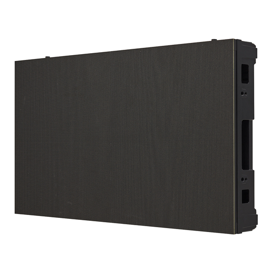
OWNER'S MANUAL
LG LED Signage
(LED SCREEN)
Please read the safety information carefully before using this product.
After reading this manual, keep it in an easily accessible location for future reference.
LSBE012-GD LSBE015-GD
LSBE018-GD LSBE025-GD
LSBE025-GF
Copyright © 2021 LG Electronics Inc. All Rights Reserved.
www.lg.com
Advertisement
Table of Contents


Need help?
Do you have a question about the LSBE012-GD and is the answer not in the manual?
Questions and answers