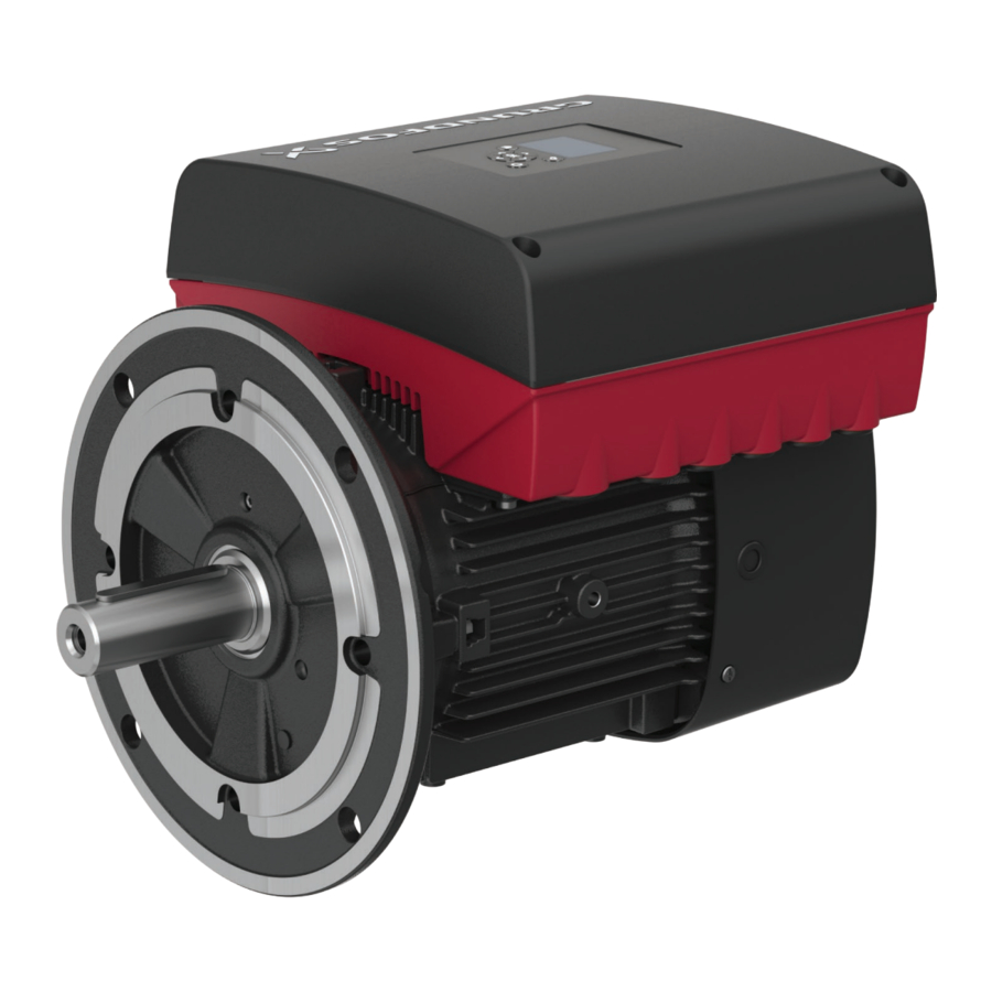
Grundfos MGE, MLE J Manual
- Service kit instructions (32 pages) ,
- Instructions manual (38 pages)
Advertisement
- 1 Service tools
- 2 Megging
- 3 Functionality test for the Safe Torque Off (STO) function
- 4 Lifting the product
-
5
Replacing hardware
- 5.1 Replacing the terminal box cover
- 5.2 Replacing the operating panel
- 5.3 Replacing the CIM module
- 5.4 Replacing the isolation cover
- 5.5 Replacing the battery
- 5.6 Replacing the functional module
- 5.7 Replacing the power board
- 5.8 Replacing the terminal box
- 5.9 Replacing the stator housing
- 5.10 Replacing the fan
- 5.11 Replacing the bearings on motors with stay bolt assembly
- 5.12 Replacing the bearings on motors with short bolt assembly
- 5.13 Replacing the IP66 gamma rings
-
6
Configuring the drive
- 6.1 Connection to the drive by means of Grundfos GO Link using Ethernet connection
- 6.2 Connection to the drive by means of Grundfos GO Link using PC-Tool Link
- 6.3 Connection to the drive by means of Grundfos GO Link using MI301
- 6.4 Connection to the drive by means of Grundfos GO via Bluetooth (BLE)
- 6.5 Configuring the drive using Grundfos GO Link
- 7 Maintenance
- 8 Fault finding
- 9 Exploded view
- 10 General information
- 11 Torques
- 12 Secondary materials
- 13 Documents / Resources
Service tools
Standard tools

| Designation | Description | Pos. | Technical data |
| Standard tools | |||
| A | Screwdriver | 156, 252b | Straight slot, 8 mm |
| B | Screwdriver | 273b, 502 | Straight slot, 3 mm |
| С | Screwdriver | 273a, 277a, 288a | Torx20 |
| Screwdriver | 152,181 268, 251d | Torx25 Torx27 | |
| Screwdriver | 178, 185, 192, 289a | Torx30 | |
| Screwdriver | 286 | Torx40 | |
| D | Ratchet spanner with socket | J, K | 17 mm |
| E | Torque screwdriver | - | 0.5 - 4 Nm |
| F+G | Torque wrench | - | 4-20 Nm |
| H | Bits kit | 152, 178,181 185, 251d, 268, 273a, 277a, 286, 287a, 288a, 289a | Tx20, Tx25, Tx27, Tx30, Tx40 |
| I | Plastic hammer or press | 156 | 1300 N (axial force) |
| J | Soft jaws | - | For vice |
| K | Locking-ring pliers, internal ring | 187 | ∅50-65 (62) mm |
| Locking-ring pliers, external ring | 188 | ∅20-30 (25) mm | |
| L | Antistatic service kit | - | 96884939 |
| M | Bearing heater | 153, 154 | |
| N | Digital scope meter | - | CAT III / 1000 V 96770121 |
Special tools

| Designation | Description | Pos. | Technical data |
| Special tools | |||
| O | Punch D20 | 156c | 98394718 |
| Punch D25 | 156c | 98394719 | |
| Punch D30 | 156c | 98394720 | |
| Punch D35 | 156c | 99124636 | |
| Punch D40 | 156c | 99124641 | |
| Punch D45 | 156c | 99124643 | |
| P | Puller for bearing | 153, 154 | |
| Q | Puller for rotor | 172 | 99197365 |
| R | Flange mounting tool for MGE 132/160 | 155 | 99110656 |
Related information
General information
Megging
 An installation with MGE motors must not be megged as this may damage the built-in electronic parts.
Motor windings may, however, be megged if the terminal box has been removed.
 Never measure between two terminals.
- Disconnect the power supply.
- Remove the terminal box.
- Measure between terminals T1, T2, T3 and earth. As windings are star-connected, fault in a winding will show when measuring all terminals.
- Replace the entire motor unit in case of fault. See also measurement of winding resistances in the section on the power board.
- Fit the terminal box.
- Switch on the power supply.
- Start the pump.
| Max. test voltage | Max. leakage current [mA] |
| 1000 VAC/1500 VDC | 35 |
Related information
Replacing the terminal box
Power board
Functionality test for the Safe Torque Off (STO) function
If the power board or the functional module is replaced, a functionality test must be performed to ensure that the Safe Torque Off (STO) function operates correctly and provides the required function. Check that the wiring complies with the wiring requirements.
Perform the following test to ensure that Safe Torque Off (STO) is functional:
- Connect the external STO signals. All 3 signals (S24, ST1, ST2) need to be shorted on the STO connector.
- Switch on power to the product.
- Start the motor. If the motor doesn't run, the STO functionality is not working.
- Open the STO signals (remove the jumper from the STO connector) and the motor will coast to a stop.
If the motor does not stop, then most probably the wrong power board version has been fitted.
 The STO signal allows the motor to run, and has a safe failure fraction of 1, meaning that any failure in the STO signal on the functional module results in a safe state and the motor cannot produce torque.
Lifting the product


Back injury
Death or serious personal injury
- Use lifting equipment and follow local regulations when lifting the product.
Falling objects
Death or serious personal injury
- Use lifting equipment rated for the weight of the product.

 Crushing of feet
Minor or moderate personal injury
- Wear safety shoes when moving the product.
The lifting brackets and/or eyebolts on the terminal box must only be used to lift the terminal box alone.
Lifting the complete motor unit
- Disconnect the power supply.
- Remove the terminal box cover (251b).
- Dismantle the power cables from the terminals (L1, L2, L3, PE) and pull them through the cable gland.
- Fit 2 eye bolts (R) to the motor.


- Attach a hook from a crane or similar lifting equipment to the eye bolts, and gently lift the complete motor unit.
Replacing hardware
Always use an antistatic service kit when handling electronic components. This prevents static electricity from damaging components. When unprotected, the component must be placed on the antistatic cloth.

Antistatic service kit
Replacing the terminal box cover
- Loosen the four screws (251d) and remove the terminal box cover (251b).
- Clean the sealing faces of the terminal box (251a) and the terminal box cover.
- Fit the terminal box cover and cross-tighten the screws. Make sure that the position of the terminal box cover is correct in relation to the operating panel (290).
 The operating panel can be turned 180°.
Related information
Replacing the operating panel
Replacing the CIM module
Replacing the isolation cover
Replacing the battery
Replacing the functional module
Replacing the power board
Replacing the terminal box
Connection to the drive by means of Grundfos GO Link using Ethernet connection
Connection to the drive by means of Grundfos GO Link using PC-Tool Link
Checking inputs and outputs
Replacing the operating panel
- Disconnect the power supply.
- Remove the terminal box cover (251b).
- Press and hold in the two locking tabs (A) while gently lifting the operating panel (B, pos. no. 290).


- Gently remove the plug for the operating panel from the functional module (273).
- Connect the plug for the new operating panel to the functional module.
- Turn the operating panel to the desired position (0° / 180°).
![]()
Do not twist the flat cable by more than 90°. - Position the operating panel correctly on the four rubber pins (C). Make sure that the locking tabs (A) are placed correctly.


- Fit the terminal box cover.
Related information
Replacing the terminal box cover
Replacing the isolation cover
Replacing the battery
Replacing the functional module
Replacing the power board
Functional module
Checking inputs and outputs
Replacing the CIM module
- Disconnect the power supply.
- Remove the terminal box cover (251b).
- Remove the plug connection for the CIM module (502).
- Remove the cover of the CIM module (287) by pressing the locking tab (A) and lifting the end of the cover (B). Then lift the cover off the hooks (C).


- Remove the screw (287a) connecting the frame connection of the CIM module to the functional module (273).
- Insert a screwdriver at the three plastic holders and loosen the CIM module from the isolation cover (277).
- Gently lift the CIM module away from the isolation cover so that the connecting plug is not damaged.


- Fit the new CIM module by aligning it with the plastic holders and the connecting plug. Press home the module using your fingers.


- Fit the frame screw in the CIM module.
- Fit the cover by leading the slits into the end with the plug connection and clicking the locking tabs onto the isolation cover.
- Press down the module using your fingers. Check that the plug has been pressed home.
- If the module is supplied with an FCC label, fix the label on the terminal box.


Related information
Replacing the terminal box cover
Replacing the isolation cover
Replacing the battery
Replacing the functional module
Replacing the power board
Replacing the isolation cover
- Disconnect the power supply.
- Remove the terminal box cover.
- Remove the operating panel (290) from the isolating cover (277).
- Remove the CIM module (502) from the isolation cover.
- Pull out the plug connections (266) using your fingers.
- Remove the screw (277a) from the isolation cover.
- You can now remove the isolation cover from the terminal box.


- Fit the new isolation cover on the terminal box. Check that the isolation cover is not clamped.
- Secure the isolation cover to the terminal box with the screw.
- Push the plug connection into the relevant terminals. They are marked so that they only fit in the right socket of the functional module.
- Fit the CIM module.
- Fit the operating panel.
- Fit the terminal box cover.
Related information
Replacing the terminal box cover
Replacing the operating panel
Replacing the CIM module
Replacing the battery
Replacing the functional module
Replacing the power board
Replacing the battery
- Disconnect the power supply.
- Remove the terminal box cover.
- Remove the operating panel (290) from the isolation cover (277).
- Remove the CIM module (502) from the isolation cover.
- Remove the isolation cover (277).
- Remove the battery (273b) from the functional module (273).
The old battery must be disposed of according to the battery directive 2006/66/EC.
Related information
Replacing the terminal box cover
Replacing the operating panel
Replacing the CIM module
Replacing the isolation cover
Replacing the functional module
The Safe Torque Off (STO) safety function cannot be retrofitted to older motors. See the section on component compatibility.
- Disconnect the power supply.
- Remove the terminal box cover.
- Remove the operating panel (290) from isolation cover (277).
- Remove the CIM module (502) from the isolation cover.
- Pull out the plug connections (266) using your fingers.
- Remove the isolation cover (277).
- Remove the spacer (286) and screws (273a).
- Gently lift the functional module (273) out of the power board so that the connecting plug (275a) is not damaged.
- Pull the connecting plug out of the functional module (or power board).
- Insert the connecting plug into the new functional module with the long end towards the module. Lead it through the module and home.
- Fit the functional module on the power board by means of the five screws. See the order of the screws on the functional module.
- Fit the spacer on the module.
- Gently push the connecting plug home.
- Fit the isolation cover.
- Push the plug connections into the relevant terminals. They are marked so that they only fit in the right socket of the functional module.
- Perform a functionality test of the Safe Torque Off (STO) function. See the section on performing the functionality test.
- Fit the CIM module.
- Fit the operating panel.
- Fit the terminal box cover.
Related information
Replacing the terminal box cover
Replacing the operating panel
Replacing the CIM module
Replacing the isolation cover
Replacing the power board
Configuring the drive
Functional module
Replacing the power board
If the power board is to be replaced, the entire lower part of the terminal box must be replaced.
- Disconnect the power supply.
- Remove the terminal box cover.
- Remove the operating panel (290) from the isolation cover (277).
- Remove the CIM module (502) from the isolation cover.
- Remove the isolation cover.
- Remove the functional module.
- Pull out the plug connection (266).
- Remove the screws (178) from the terminal box (251a) and gently lift the terminal box off the motor (150).
- Fit the new terminal box on the motor. Make sure that the plug connections are aligned.
- Cross-tighten the screws of the terminal box.
- Fit the plug connection for power supply.
- Fit the functional module.
- Fit the isolation cover.
- Fit the CIM module.
- Fit the operating panel.
- Fit the terminal box cover.
Related information
Replacing the terminal box cover
Replacing the operating panel
Replacing the CIM module
Replacing the isolation cover
Replacing the functional module
Configuring the drive
Power board
Replacing the terminal box
- Disconnect the power supply.
- Remove the terminal box cover.
- Disconnect all relevant wires.
- Remove the screws (178) from the terminal box (251a) and gently lift the terminal box off the motor (150).
- Fit the new terminal box on the motor. Make sure that the plug connections are aligned.
- Cross-tighten the screws of the terminal box.
- Move relevant modules to the new terminal box according to the section above.
- Connect all relevant wires.
- Transfer data from the nameplate of the old terminal box to the nameplate of the new one.


- Fit the terminal box cover.
Related information
Megging
Replacing the terminal box cover
Replacing the stator housing
- Disconnect the power supply.
- Remove the screws (178) and take the terminal box (251a and 251b) out of the stator housing (150).
![warning]() Support the terminal box when you remove the motor.
Support the terminal box when you remove the motor. - Remove the stator housing according the service instructions of the system.
- Install the stator housing in the system according to the service instructions of the system.
- Fit the terminal box on the stator housing and cross-tighten the screws.
Related information
Replacing the fan
Dismantling
Replacing the IP66 gamma rings
Replacing the fan
- Disconnect the power supply.
- Remove the terminal box.
- Remove the screws (152) and lift off the fan cover (151).
- Insert two screwdrivers close to the shaft and remove the fan (156).


- Push the fan on the shaft. Alternatively, gently knock the fan onto the shaft (172) by means of a plastic hammer while holding the drive end of the shaft against a solid surface.
- Fit the fan cover on the stator housing (150) and tighten the screws (152).
- Fit the terminal box on the stator housing and cross-tighten the screws.
Related information
Replacing the stator housing
Dismantling
Replacing the IP66 gamma rings
Replacing the bearings on motors with stay bolt assembly
Dismantling
- Disconnect the power supply.
- Remove the stator housing from the terminal box.
- Remove the fan.
- Remove the parallel key (172a) from the drive-end of the shaft.
- Remove the gamma rings (159d and 159e) or seal rings (156c and 156d) from the drive end and non-drive end of the shaft.
- Fit the puller on the pump housing: Remove the eyebolts, place the puller and fit the eyebolts again to lock the puller in place.


- Remove the staybolts (181).
- Push the rotor out of the stator using the puller. Note the drain plug position.

Pos. Description 1 Drainhole

- Remove old sealant if any, from the stator seating and flange.
- Wrap the rotor in a protective material, such as cardboard, to protect it from scratches.
- Place the rotor on the vice. Do not tighten the vice on the rotor!
Correct position of the rotor on the vice

- Pull the flange from the rotor with a puller.

- Remove the locking ring (188) from the shaft.

- Remove the bearing (153) with a puller.


Related information
Replacing the stator housing
Replacing the fan
Assembly
 Hot surface
Minor or moderate personal injury
- Use heat-resistant gloves.
 Crushing of hands
Minor or moderate personal injury
- Watch your fingers when you insert the rotor, as the magnet will pull rotor and stator together with big force.
- Place the rotor on a vice.
![]()
Do not tighten the vice on the rotor. - Clean the bearing journal in the drive end with a clean cloth.
- Heat the new bearing (153) to a temperature between 90 and 110°C. Follow the instructions for the bearing and bearing heater.
- Fit the heated bearing on the drive end of the shaft.
- Fit the locking ring (188) on the shaft.
- Place the flange in the vice.
- Clean the bearing seat with a clean cloth and lubricate the bearing seat with anti-fretting paste.
- Fit the rotor in the flange.


- Fit the locking ring (187) so that the bearing is held by the flange.
- Clean the bearing journal in the non-drive end with a clean cloth.
- Heat the bearing (154) to a temperature between 90 and 110°C.
- Fit the heated bearing (154) on the shaft (172).
- Remove the cardboard from the rotor when the bearings have cooled down.
- Check that the corrugated spring (158) is correctly fitted in the stator housing.
- Apply Loctite 5512 on the flange surface which seals against the stator.
- Gently insert the stator onto the rotor.


- Unscrew the puller to slowly insert the rotor into the stator. Press the flange and the stator together when the bearing (154) has engaged with the stator housing. Check that the drain hole of the flange faces downwards.
- Cross-tighten the staybolts (181).
- Remove the puller and fit the eyebolts (189) back on the motor.
- Lubricate the shafts ends.
- Fit the seal rings (156c and 156d) or the gamma rings (159d and 159e) on the drive end and non-drive end of the shaft. Use a punch.

- Fit the parallel key (172a) on the drive-end of the shaft.
- Check that the shaft can rotate freely.
- Fit the fan and cover.
- Fit the terminal box.

Replacing the bearings on motors with short bolt assembly
Dismantling
- Disconnect the power supply.
- Remove the stator housing from the terminal box.
- Remove the fan.
- Remove the parallel key (172a) from the drive end of the shaft.
- Remove the gamma rings (159d and 159e) or the seal rings (156c and 156d) from the drive end and non-drive end of the shaft.
- Remove the screws (206) from the non-drive end flange (156a).
- Remove the non-drive end flange (156a).
- Remove the corrugated spring (158) from the non-drive end of the shaft.
- Remove the bearing (154) with a puller.

- Remove the screws (208) holding the bearing plate from the drive end flange (156b).
- Remove the screws (185) and nuts (208b) holding the drive-end flange.
- Remove the drive-end flange (156b).
- Remove the locking ring (188).

- Remove the bearing (153) with a puller.
- Remove the bearing cover (155).


Related information
Replacing the stator housing
Replacing the fan
Assembly
Hot surface
Minor or moderate personal injury
- Use heat-resistant gloves.
- Fit the O-rings (150b).
- Clean the bearing journal in the non-drive end with a clean cloth.
- Lubricate the bearing.

- Heat the new bearing (154) to maximum 110°C. Follow the instructions of bearing and bearing heater.
- Fit the heated bearing (154) on the shaft (172).
- Fit the corrugated spring (158) in the non-drive end flange (156a).
- Fit the non-drive end flange (156a) on the stator housing.
- Fit the washers (207a) and screws (206), and cross-tighten the screws.
- Clean the bearing journal in the drive end with a clean cloth.
- Lubricate the bearing.

- Fit the bearing cover (155).
- Heat the new bearing (153) to a temperature between 90 and 110°C.
- Fit the heated bearing (153) on the shaft (172).


- Fit the locking ring (188).

- Fit the drive-end flange (156b). Use a thin pin to align the holes of the bearing plates (155) with the holes of the flange.

- Use the flange mounting tool (Q) and nuts (208b) to fit the drive-end flange home onto the stator housing.

- Remove the flange mounting tool and nuts. The flange must stay in place.
- Fit the screws (185) and nuts (208b). Cross-tighten the screws.
- Fit the gaskets (208a) and screws (208) in the two available holes of the flange.
- Remove the pin and fit the last gasket (208a) and screw (208).
- Lubricate the shaft ends and fit the seal rings (156c and 156d) or gamma rings (159d and 159e). Use a punch.


- Fit the parallel key (172a) on the drive end of the shaft.
- Check that the shaft can rotate freely.
- Fit the fan and cover.
- Fit the terminal box.
Replacing the IP66 gamma rings
- Disconnect the power supply.
- Remove the stator housing from the terminal box.
- Remove the fan.
- Remove the parallel key (172a) from the shaft.
- Remove the gamma rings (159d) from the shaft (172).
- Lubricate the new gamma ring (159d) and fit it on the drive end of the shaft.
- Lift the motor so that the non-drive end of the shaft rests on a solid, vibration-free surface.
- Gently knock the ring home with the relevant punch. The distance between the flange (156b) and ring must be 0.8 to 1.3 mm.
![information]() The design of the punch ensures correct tolerances.
The design of the punch ensures correct tolerances.


- Fit the parallel key (172a), if any, on the shaft.
- Support the motor so that it rests on the drive end of the shaft.
- Lubricate the new gamma ring (159e) and fit it on the non-drive end of the shaft.
- Gently knock the ring home with the relevant punch. The distance between the stator housing (150) and ring must be 0.8 to 1.3 mm.


- Fit the fan and cover.
- Fit the terminal box.
Related information
Replacing the stator housing
Replacing the fan
Configuring the drive
The drive is configured from factory for the intended application and pump type. The configuration file number can be found on the drive configuration label which is placed inside the drive. See the below figure.

If the drive, functional module or power board is replaced or mounted on another motor, it must be reconfigured.
Use Grundfos GO Link or Grundfos GO for that purpose. To establish connection to the motor, use Bluetooth, Ethernet, PC-Tool Link or Grundfos MI301.
Related information
General information
Replacing the functional module
Replacing the power board
Connection to the drive by means of Grundfos GO Link using Ethernet connection
Equipment
- Grundfos GO Link, version 01.02.00 or newer
- Cat. 5 Ethernet cable
Procedure
- Remove the terminal box cover. See the section on replacing the terminal box cover.
- Connect a laptop to the Ethernet connector in the terminal box by means of the Ethernet cable.
- Open Grundfos GO Link and connect to the pump.
Related information
Replacing the terminal box cover
Connection to the drive by means of Grundfos GO Link using PC-Tool Link
Equipment
- Grundfos GO Link, version 01.02.00 or newer
- Grundfos PC Tool Link
- GENIbus cable (RS-485).
Procedure
- Remove the terminal box cover. See the section on removing the terminal box cover.
- Connect PC Tool Link to the GENIbus terminals on the motor by means of the GENIbus cable. Connect directly to AYB terminals (ensure that AYB terminals are set to GENI and not Modbus) or AYB terminals on a CIM50 card (Multi-E/multipump systems).
Connection of GENIbus

- Open Grundfos GO Link and connect to the pump.

Related information
Replacing the terminal box cover
Connection to the drive by means of Grundfos GO Link using MI301
Equipment
- Grundfos GO Link, version 01.02.00 or newer
- Grundfos MI301
Procedure
- Turn on the MI301.
- Open Grundfos GO Link and connect to the pump using either Direct connect or Radio scan.
Connection to the drive by means of Grundfos GO via Bluetooth (BLE)
Equipment
- Grundfos GO app
- iOS or Android device
Procedure
- Open the Grundfos GO app and connect to the pump using Bluetooth.
Configuring the drive using Grundfos GO Link
The GO Link configuration must only be carried out by service technicians trained in the task and possessing at least Service Engineer level access.
- Select Standard config > By number
- Fill in the number from the sticker inside the drive and select Search.
- Select the file in the list and click Send. The drive is now configured with default data and is now ready to be set for the specific installation.


Maintenance
Lubricating the bearings
Lubricate the bearings through the grease nipples with a grease dispenser and high-temperature grease as specified on the bearing nameplate. The display indicates the number of bearing relubrications that has been done since the last bearing replacement. For more information about the display, see the section on motor bearing monitoring.
The factory-set interval between relubrications is stated on the bearing nameplate placed on the motor. The relubrication interval can be changed by a Grundfos service technician.
It is possible to relubricate the bearings five times according to the preset interval. When the preset interval has been reached after the fifth relubrication, a warning will be given to replace the bearings.
In the case of seasonal operation (motor is idle for more than six months of the year), we recommend that you lubricate the motor bearings when you take it out of operation.
It is important to relubricate the bearings as specified on the motor nameplate with mechanical data. If this interval is not observed, the bearing life will be reduced.
Reduced lubricating interval
The lubricating interval must be reduced in these situations:
- Dirty and dusty environments. Reduce the lubricating interval by a factor 0.75.
- Very moist environments. Reduce the lubricating interval by a factor 0.9.
If the environments are both dusty and moist, multiply the factors.
Grease type and quantity
See the bearing nameplate.
Never mix grease with thickeners, such as lithium-based grease with polycarbamide-based grease.
Motor bearing monitoring
Use this function to select whether or not you want to monitor the motor bearings. You can make the following settings:
- Active
- Not active
When the function is set to Active, a counter in the controller starts counting the running hours of the bearings. The running hours are calculated on the basis of the motor speed. When a predefined limit is reached, a warning indicates that the bearings must be replaced or relubricated.
If you change the function to Not active, the counter continues to count. However, no warning is given when it is time to replace the bearings. If you change the function to Active again, the accumulated running hours are used to recalculate the replacement time.
Fault finding
General information
- Check the mains supply to the pump.
- Read fault messages by means of Grundfos Eye, Grundfos GO, Grundfos GO Link or the graphical operating panel, if fitted.
![information]() Make a copy of motor settings.
Make a copy of motor settings. - If possible, test if the motor can run without load. Remove the coupling to the pump, if possible, and set the operating signal to maximum by means of Grundfos GO Link, Grundfos GO or the operating panel.
You can reset a fault indication in the following ways:
- When the fault cause has been eliminated and the pump is switched on, the pump will revert to normal duty.
- If the fault disappears by itself, the fault indication will automatically be reset.
The fault cause will be stored in the pump alarm or warning log.
Fault indications via Grundfos Eye
See the indication of motor status by means of Grundfos Eye and the contact positions of signal relays in the installation and operating instructions for the MGE, MLE motor.
Fault indications via Grundfos GO
See the description of the Grundfos GO operating panel and possibilities of communication in the installation and operating instructions for the MGE, MLE motor.
Alarms and warnings shown in Grundfos GO

Alarm and warning log of Grundfos GO

For a detailed description of the fault, see the display "Assisted fault advice".
Detailed fault description

Fault and warning signals
The fault indication below can be read by the number in brackets, text or status indications on the operating panel, depending on the equipment available.
| Grundfos Eye | Cause | Remedy |
Two opposite red indicator lights flashing simultaneously. (Alarm indication) | External fault (3) | |
| An external signal reports an external fault to the digital input set for this function. |
| |
| Too many restarts (4) | ||
| The pump restarts too many times due to a fault that forces the pump to stop and restart automatically. |
| |
| Overvoltage (32) | ||
| The supply voltage to the pump is too high. |
| |
| Undervoltage (40) | ||
| The supply voltage to the pump is too low. |
| |
| Undervoltage transient from mains supply (41) | ||
| The supply voltage to the pump shows signs of voltage drops. |
| |
| Overload (49) | ||
| The motor is overloaded and has automatically reduced the speed, thereby reducing the pump performance. |
| |
| Blocked pump (51) | ||
| The pump is blocked. |
| |
| STO Active Indication (62) | ||
| The Safe Torque Off (STO) function are activated by an external device. |
| |
| One yellow indicator light permanently on. (Warning indication)  | Pump communication fault (10) | |
| There is a communication fault between this pump and the other pumps of the multipump system. |
| |
| Forced pumping (29) | ||
| Other pumps or sources force flow through the pump even if the pump is stopped. |
| |
| Dry running (56, 57) | ||
| There is no water at the pump inlet, or the water contains too much air. |
| |
| Internal fault (72, 83, 85, 155, 157, 163) | ||
| There is an internal fault in the pump electronics. |
| |
| High motor temperature (65, 66) | ||
| The motor temperature is too high. |
| |
| Internal communication fault (76) | ||
| There is a communication fault between different parts of the electronics. |
| |
| Soft pressure buildup, timeout (215) | ||
| The system is in the mode "soft pressure buildup" longer than the set time limit. |
| |
| One yellow indicator light rotating in the direction of rotation of the motor when seen from the non-drive end. (Warning indication)  | Replace the motor bearings (30) | |
| The bearings are worn. |
| |
| Internal sensor fault (88) | ||
| The pump receives a signal from the internal sensor which is out of the normal range. |
| |
| Pt100/1000 sensor 1 (91) and 2 (175) | ||
| Pt100/1000 input 1 receives a signal which is out of the normal range. |
| |
| Supply fault, 5 V (161) | ||
| Fault in the output voltage to the sensor or potentiometer. |
| |
| Supply fault, 24 V (162) | ||
| Fault in the output voltage. |
| |
| Signal fault, LiqTec-sensor (164) | ||
| The pump receives a signal from the LiqTec sensor which is out of the normal range. |
| |
| Signal fault, sensor 1 (165), 2 (166) and 3 (167) | ||
| Analog input 1, 2 or 3 receives a signal which is out of the normal range. |
| |
| Limit 1 exceeded (190) and limit 2 exceeded (191) | ||
| Limit 1 or 2 reaches the limit for warning or alarm. |
| |
Functional module

Electric shock
Death or serious personal injury
- Do not touch the terminals of the power board as they are still live.
- Do not touch the relay RL1 as it may still be live.
Measuring equipment must be free of static electricity or have the same potential as the motor before being used for measurement without isolation cover.
The status diode of the functional module flashes 150 times/minute when the software is running correctly. See the figure below. The functional module can only function if the power board is in operation, as the power board supplies voltage to the functional module.
| Status | Fault |
| Permanently on | The microprocessor is frozen. The functional module is defective. |
| Light off | The functional module is defective. |
| Flashing 150 times/minute | The processor of the functional module is functional |
Status diode of functional module

If the light diode is flashing, the functional module is working correctly. The fault may then be in the operating panel. If the status diode of the functional module is off, check if the power board supplies voltage by measuring 8.5 VDC on the VFE plug connection between the functional module and the power board (J15). If no voltage is measured, the connection between the modules or the power board is defective. If the VFE voltage to the functional module is okay, check if the voltage between the reference point and the other measuring points is okay. The voltage values apply to an operating motor.
Measuring voltage on the functional module

Use a correctly calibrated measuring instrument.
To measure the voltage listed in the table below, you must use the same reference point (Ref.) seen on the figure above. Measure the DC voltage from, for example, "Ref." to "3". The measure should be between 14.5 and 15.7 V.
| Pos. | Control voltage [VDC] | ||
| Minimum | Nominal | Maximum | |
| VFE (J15) | 8.5 | ||
| 1 | 4.8 | 5 | 5.2 |
| 2 | 3.2 | 3.3 | 3.4 |
| 3 | 14.5 | 15.1 | 15.7 |
| 4 | 4.8 | 5 | 5.2 |
| 5 | 23 | 23.9 | 24.9 |
| 6 | 4.8 | 5 | 5.2 |
| 7 | VFE | ||
| Ref. | GND | ||
Related information
Replacing the operating panel
Replacing the functional module
Checking inputs and outputs
Make a copy of the motor settings.
Pt100/1000
Use a 100 Ω resistance and decide on the basis of the motor settings which value this resistance will show in the display when connected to the terminals instead of the Pt100/1000 sensor.
Analog input, AI
It is possible to measure on the analog input to determine if its function is correct.
During current state, a 292 Ω resistance in the input converts a current signal (e.g. 0-20 mA) from the sensor to a voltage signal for the processor. Measure the voltage across the input and read the current in the circuit by means of Grundfos GO or PC Tool. The current value must be equal to voltage divided with resistance. Alternatively, a milliammeter can be connected in series with the circuit.
Measuring on analog input

Next step is to test the input in voltage state. Change the setup of the input to voltage state (0-10 V). Fit a jumper between terminal 5 (+5 V) and the analog input. 5 V must now be read by means of the PC Tool.
Testing the input during voltage state

Change the setup of the input to current state and measure on the input using an ohmmeter. The resistance must be 292 Ω. In voltage state, the resistance is 122 kΩ.
Measuring resistance in current and voltage state

Analog output, AO
The analog input is protected against short circuit and will shut down the signal in case of short circuit. If you suspect a short circuit, remove the load and compare the value read via PC Tool with the value measured by means of the measuring instrument.
If the values are not identical, the module is defective.
Digital input, DI
See the settings of the input in PC Tool.
Connect the digital input to frame (GND) by means of an ammeter. The value measured must now be approximately 12 mA. Check that PC Tool shows a corresponding value.
Testing the digital input

Digital output, DO/open collector, OC
See the settings of the output in PC Tool. Measure the output. If the value in PC Tool differs from the value measured with the measuring instrument, remove the load. If the values still differ, the module is defective. The voltage of an active output is approximately 5 V.
Measuring voltage on the digital output

LiqTec sensor
Connect a new LiqTec sensor to check the input. Immerse the sensor into water and take it up. The motor must now report fault within 20 seconds.
Signal relay
See the settings of the output in PC Tool.
Check if the relay reacts to the signals of the controller according to the configuration of the controller.
CIM
Test the CIM module according to its manual.
Radio
If there are problems in the radio connection between Grundfos GO and the motor, remove the terminal box cover. See the section on replacing the terminal box cover. Replace the operating panel if there is still no connection.
Battery
Switch off power to the motor for a short period. When you switch on the power to the pump again, adjust the clock.
Operating panel (HMI)
Check the flat cable to the functional module. Replace the operating panel if the connection is correct, and it did not solve the problem.
Related information
Replacing the terminal box cover
Replacing the operating panel
Power board
Electric shock
Death or serious personal injury
- Do not touch the terminals of the power board as they are still live.
Measuring equipment must be free of static electricity or have same potential as the motor before being used for measurement without isolation cover.
If reading of fault codes does not provide a clear answer as to whether the power board is functioning correctly, you can proceed as described below.
- Check that the voltage to the power board is within the limit values stated on the nameplate. Check all phases of a threephase motor.
- If there are signs of moisture in the terminal box, take necessary precautions to prevent similar faults.
- Check the two status diodes of the power board by looking through dedicated holes in the PCB. Status diode "LED 5V" must be permanently on when connected to mains. Status diode "LED Micro controller" flashes when the functionality is correct. See the tables below.
![caution]() It may be necessary to dim the light as the diode light is weak.
It may be necessary to dim the light as the diode light is weak. Status, three-phase Fault The LED Micro controller is permanently on. - The microprocessor is frozen.
- No initialising message from the functional module.
The LED Micro controller is off. The power board is defective. The LED Micro controller is flashing with a constant frequency. The processor of the power board is functional. LED 5V is permanently on. The processor of the power board is functional. LED 5V is off. The power board is defective. LED 5V and LED Micro Controller are flashing simultaneously. - Short circuit in the connection to the functional module.
- Short circuit in the functional module.
- The functional module is disconnected.
- The power board is defective.
Status diodes of the power board, Type 1

Status diodes of the power board, Type 2


- Measure the DC voltage across the capacitors (GND and DC+) to ensure that the capacitors are not short-circuited. If the function is correct, the voltage must be ≥ 566 V (at a mains voltage of 400 V). See the figures on status diode of functional module and status diodes of power board, Type 4. If not, the power board is defective.
Status diodes of the power board, Type 3

Status diodes of the power board, Type 4


Related information
Megging
Replacing the power board
Winding resistance
As the motor is star-connected, the easiest way to measure the winding resistance is to measure across two phases. Measure at the coil temperatures stated in the table below. It may be necessary to let the motor cool off if it has been running or if it was stopped because of short circuit or overload.
Wiring diagram

| Pos. | Description |
| T1 | U1 |
| T2 | V1 |
| T3 | W1 |
Measuring the winding resistance, frame sizes 90, 100, 112 and 132

Measuring the winding resistance, frame sizes 132 and 160


Exploded view

Frame sizes 90, 100, 112 and 132 with stay bolt assembly of stator house

Frame sizes 132 and 160 with short bolt assembly of stator house

General information

Read this document before you start service work on the product. Service work must comply with local regulations and accepted codes of good practice. Observe the safety instructions for the product.
Related information
Torques
Secondary materials
Service tools
Configuring the drive
Hazard statements
The symbols and hazard statements below may appear in Grundfos installation and operating instructions, safety instructions and service instructions.

Indicates a hazardous situation which, if not avoided, will result in death or serious personal injury.
Indicates a hazardous situation which, if not avoided, could result in death or serious personal injury.
Indicates a hazardous situation which, if not avoided, could result in minor or moderate personal injury.
The hazard statements are structured in the following way:
SIGNAL WORD
Description of the hazard
Consequence of ignoring the warning
- Action to avoid the hazard.
Notes
The symbols and notes below may appear in Grundfos installation and operating instructions, safety instructions and service instructions.
 | Observe these instructions for explosion-proof products. |
| A blue or grey circle with a white graphical symbol indicates that an action must be taken. |
| A red or grey circle with a diagonal bar, possibly with a black graphical symbol, indicates that an action must not be taken or must be stopped. |
| If these instructions are not observed, it may result in malfunction or damage to the equipment. |
| Tips and advice that make the work easier. |
Safety information for working on the product
These service instructions apply to MGE and MLE model J motors.
The safety instructions for this product and for the system which it is part of must be available during service of the product.
Position numbers of parts (digits) refer to drawings and parts lists; position numbers of tools (letters) refer to the section about service tools. Electrical parts must only be serviced by Grundfos or an authorised service workshop.

Biological hazard
Death or serious personal injury
- Use personal protective equipment if there is a risk of getting into contact with the pumped liquid.
- Observe local regulations.
Hot surface
Death or serious personal injury
- Do not touch the product while it is running. Allow surfaces to cool before servicing.
 Sharp element
Minor or moderate personal injury
- When servicing the product, wear protective gloves to avoid cutting your hands on sharp edges.
 Cold surface
Minor or moderate personal injury
- Make sure that no one can accidentally come into contact with cold surfaces. Wear protective gloves.
Component compatibility for the Safe Torque Off (STO) functionality
The Safe Torque Off (STO) safety function cannot be retrofitted to older motors.
For full feature level on the individual functional modules, it is important to choose the right component combination. For STO functionality Generation 2 power boards are required. See the below tables.
| Incompatible combination | |
| Generation 1 power boards | Functional module |
| PB331 | FM110 FM310 FM311 |
| PB341 | |
| PB351 | |
| PB361 | |
| Compatible combination | |
| Generation 2 power boards | Functional module |
| PB332 | FM110 FM310 FM311 |
| PB342 | |
| PB352 | |
| PB362 | |
You can identify the fitted power board by means of the motor nameplate:

Before dismantling

Electric shock
Death or serious personal injury
- Switch off the power supply and make sure that it cannot be accidentally switched on. The power supply must be switched off for at least five minutes before you start working on the motor.
- Check that other pumps or sources do not force flow through the pump even if the pump is stopped. This will cause the motor to act like a generator, resulting in voltage on the terminals.
- Tighten the cable glands to the recommended torques.
- Connect the product to protective earth and provide protection against indirect contact in accordance with local regulations.
- Close the isolating valves, if fitted, and make sure that they cannot be accidentally opened.
- Before starting work on the product, let the product and pumped liquid cool off.
During assembly
- Lubricate and tighten screws and nuts according to the sections about torques and secondary materials.
After assembly
- If analog or digital inputs, the relay output or the CIM module has been removed from the functional module, check the communication with external units after service.
Torques

- Screws of new terminal box lower parts must be tightened to 6.5 - 7 Nm.
- Frame sizes 90, 100, 112 and 132 with stay bolt assembly of stator house.
- Frame sizes 132 and 160 with short bolt assembly of stator house.
Torques for terminals
| Terminal | Thread size | Maximum torque [Nm] |
| L1, L2, L3, L, N | M4 | 2.2 |
| PE | M5 | 6 |
| NC, C1, C2, NO | M3 | 0.5 |
| DI1, DI2, DI3, DI4, AI1, AI2, AI3, AO1, PT1, PT2, LT1, LT2, GND, 24V, 5V, TX, RX, A, Y, B, S24, ST1, ST2 | M3 | 0.5 |
Related information
General information
Secondary materials
| Pos. | Designation | Quantity [kg] |
| 156c, d | Castrol LMX grease | 0.1 |
| 159d, e | ||
| 153, 154 | Mobil Unirex N3 grease | 0.1 |
| 156a, b | SKF anti-fretting agent LGAF 3E | 0.1 |
| 156a, b 150 | Loctite 5512 | - |
Related information
General information
Documents / ResourcesDownload manual
Here you can download full pdf version of manual, it may contain additional safety instructions, warranty information, FCC rules, etc.
Advertisement


Need help?
Do you have a question about the MGE and is the answer not in the manual?
Questions and answers