Table of Contents
Advertisement
Quick Links
MODEL TF1450
14500-WATT
TRI FUEL GENERATOR
Instruction Manual
NEED HELP? CONTACT US!
Have product questions? Need technical support? Please feel free to contact us:
1-847-429-9263 (M-F 8AM-5PM CST)
TECHSUPPORT@WENPRODUCTS.COM
IMPORTANT: Your new tool has been engineered and manufactured to WEN's highest standards for dependability,
ease of operation, and operator safety. When properly cared for, this product will supply you years of rugged,
trouble-free performance. Pay close attention to the rules for safe operation, warnings, and cautions. If you use
your tool properly and for its intended purpose, you will enjoy years of safe, reliable service.
WENPRODUCTS.COM
For replacement parts and the most up-to-date instruction manuals, visit
Advertisement
Table of Contents

Related Manuals for Wen TF1450


Summary of Contents for Wen TF1450
- Page 1 1-847-429-9263 (M-F 8AM-5PM CST) TECHSUPPORT@WENPRODUCTS.COM IMPORTANT: Your new tool has been engineered and manufactured to WEN’s highest standards for dependability, ease of operation, and operator safety. When properly cared for, this product will supply you years of rugged, trouble-free performance. Pay close attention to the rules for safe operation, warnings, and cautions. If you use your tool properly and for its intended purpose, you will enjoy years of safe, reliable service.
-
Page 2: Table Of Contents
CONTENTS WELCOME Specifications ....................3 Introduction ......................4 SAFETY General Safety Rules ..................5 Generator Safety Warnings ................7 BEFORE OPERATING Know Your Generator ..................10 Unpacking & Packing List ................12 Assembly & Adjustments ................13 Generator Preparation ..................14 OPERATION & MAINTENANCE Starting Your Generator ..................21 Using Your Generator ..................23 Shutting Off Your Generator ................26 Maintenance ....................27... -
Page 3: Welcome
SPECIFICATIONS GENERATOR Model Number TF1450 Gasoline: 14500W Surge (Starting) Wattage Propane: 12500W Natural Gas: 10500W Gasoline: 11500W Rated (Running) Wattage Propane: 10300W Natural Gas: 8750W AC: 120V / 240V Rated Voltage DC: 12V AC: 47.9A (Gas), 42.9A (LPG), 36.4A (NG) Rated Amperage DC: 8.3A... -
Page 4: Service Record
INTRODUCTION Thanks for purchasing the WEN 14500-Watt Tri Fuel Generator. Refer to the illustration below for the location of the serial number on the specifications label. Record the generator information in the spaces provided below. If as- sistance for information or service is required, please contact customer service by calling 1-847-429-9263, M-F 8-5 CST;... -
Page 5: Safety
GENERAL SAFETY RULES WARNING! Read all safety warnings and all instructions. Failure to follow the warnings and instructions may result in electric shock, fire and/or serious injury. Safety is a combination of common sense, staying alert and knowing how your item works. The term “power tool” in the warnings refers to your mains-operated (corded) power tool or battery-operated (cordless) power tool. -
Page 6: California Proposition 65 Warning
GENERAL SAFETY RULES WARNING! Read all safety warnings and all instructions. Failure to follow the warnings and instructions may result in electric shock, fire and/or serious injury. Safety is a combination of common sense, staying alert and knowing how your item works. The term “power tool” in the warnings refers to your mains-operated (corded) power tool or battery-operated (cordless) power tool. -
Page 7: Generator Safety Warnings
GENERATOR SAFETY WARNINGS DANGER! CARBON MONOXIDE Using a generator indoors CAN KILL YOU IN MINUTES. Generator exhaust contains carbon monoxide (CO). This is a poison gas you cannot see or smell. If you can smell the generator exhaust, you are breathing CO. But even if you cannot smell the exhaust, you could be breathing CO. -
Page 8: Operating Environment
GENERATOR SAFETY WARNINGS WARNING! Do not let comfort or familiarity with the product replace strict adherence to product safety rules. Failure to follow the safety instructions may result in serious personal injury. OPERATING ENVIRONMENT 3. If any part of the generator, electrical device or pow- er cord is broken, damaged, or defective, make sure 1. - Page 9 GENERATOR SAFETY WARNINGS WARNING! Do not let comfort or familiarity with the product replace strict adherence to product safety rules. Failure to follow the safety instructions may result in serious personal injury. TO MAXIMIZE THE LIFESPAN OF YOUR GENERATOR: We recommend running your generator at least once a month for 20 to 30 minutes.
-
Page 10: Before Operating
KNOW YOUR GENERATOR TOOL PURPOSE Generators provide you with power when and where you need it most. Refer to the following diagrams to become familiarized with all the parts and controls of your Generator. The components will be referred to later in the manual for assembly and operation instructions. -
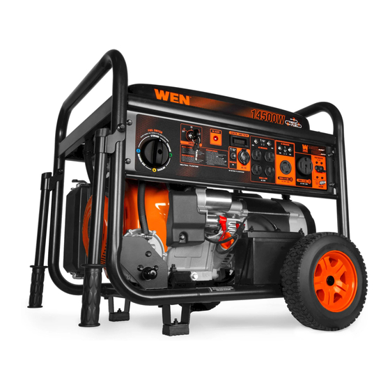
Page 11: Control Panel
KNOW YOUR GENERATOR CONTROL PANEL 1. Fuel Selector Switch 8. Main Circuit Breaker Turn the dial to easily switch between gasoline, propane, Push the button to reset the circuit. and natural gas before operation. 9. Grounding Nut 2. Engine Key Switch Connection point for grounding the generator to the Start and shut off the engine. -
Page 12: Unpacking & Packing List
UNPACKING & PACKING LIST UNPACKING With the help of a friend or trustworthy foe, such as one of your in-laws, carefully remove the generator from the packaging and place it on a sturdy, flat surface. Make sure to take out all contents and accessories. Do not discard the packaging until everything is removed. -
Page 13: Assembly & Adjustments
ASSEMBLY & ADJUSTMENTS TO INSTALL THE FEET: 1. Insert two M8x16 bolts (1) through the foot support assembly (2) and frame. Tighten with two M8 nuts (3). 2. Repeat step 1 for the other foot. TO INSTALL THE WHEELS: 1. Slide the wheel axle (4) through the wheel (5), flat washer (6), and wheel bracket on the frame. 2. -
Page 14: Generator Preparation
4. Reinstall the oil dipstick and firmly tighten it. Wipe clean any spilled oil. NOTE: Extend the lifespan of your generator by catching the loose metal filaments that naturally build up inside the crank case with the WEN Magnetic Dipstick (Model GNA273), available for purchase at wenproducts.com. Lower Fill Line... - Page 15 GENERATOR PREPARATION TO CHECK OIL LEVEL (before every subsequent start): Fig. 5 1. Place the generator on a level surface. Make sure the engine is OFF before adding or checking oil. 2. Remove and wipe the dipstick with a clean rag. Upper Limit 3.
- Page 16 GENERATOR PREPARATION TO ADD GASOLINE: Fig. 6 1. Place the generator on a level surface. Make sure the engine is OFF before adding or checking the fuel. 2. Unscrew the fuel cap (Fig. 6) and set it aside. The fuel cap may be tight and hard to unscrew.
- Page 17 GENERATOR PREPARATION FUEL OPTION B: LIQUID PETROLEUM GAS (LPG) (CONT.) NOTE: LPG regulator inlet pressure is approximately 30 PSI at 0 °F, and 218 PSI at 100 °F. • You can use LPG tanks with Type 1, right hand Acme threads with this generator. Verify that the qualification date on tank has not expired.
- Page 18 GENERATOR PREPARATION FUEL OPTION C: NATURAL GAS (NG) Fig. 8 1. We recommend using Teflon or other PTFE tape when securing the threaded male end of the NG hose (not included) to the supply line. A 25-foot 1/2-inch NG hose with quick-connector is available for pur- chase at wenproducts.com (part no.
-
Page 19: Step 3 - Connect The Battery
GENERATOR PREPARATION STEP 3 - CONNECT THE BATTERY WARNING! BATTERY GIVES OFF EXPLOSIVE HYDROGEN GAS. • Keep battery away from spark, flame, or cigarette. • Do not connect or disconnect battery while generator is running. • Service or use battery only in well ventilated areas. WARNING! Battery contains sulfuric acid. -
Page 20: Step 4 - Ground The Generator
GENERATOR PREPARATION STEP 4 - GROUND THE GENERATOR Fig. 10 To reduce the risk of electric shock and to maximize safety, the generator should be properly grounded. Ground the generator by tightening the grounding nut on the front control panel (Fig. 10) against a grounding wire. A generally acceptable grounding wire is a No. -
Page 21: Operation & Maintenance
STARTING YOUR GENERATOR Before starting the generator, make sure you have read and performed the steps in the “Generator Preparation” sec- tion of this manual. If you are unsure about how to perform any of the steps in this manual please call 1-847-429-9263 (M-F 8-5 CST) for customer service. -
Page 22: Before Starting The Generator
STARTING YOUR GENERATOR BEFORE STARTING THE GENERATOR Fig. 11 1. Verify that the generator is outside on a dry, level sur- face. Allow at least two feet of clearance on all sides of the generator. 2. To maximize safety, check that the generator is properly grounded (see “Ground the Generator”). -
Page 23: Using Your Generator
USING YOUR GENERATOR CALCULATING THE WATTAGE OF YOUR DEVICE(S) Connect electrical devices running on AC current according to their wattage requirements. Calculate the total run- ning wattage and starting wattage of the device(s) you wish to connect, and MAKE SURE that they are within the capacity of your generator and the capacity of each individual outlet. - Page 24 USING YOUR GENERATOR CALCULATING THE WATTAGE OF YOUR DEVICE(S) - CONTINUED The chart below serves as a reference for the estimated wattage requirements of common electrical devices. How- ever, do not solely rely on this chart - all electronics and appliances are built differently. Always check the wattage listed on the electrical device before consulting this chart.
-
Page 25: Connecting Electrical Devices
USING YOUR GENERATOR CONNECTING ELECTRICAL DEVICES CAUTION: Become familiar with the functions and capacity of each component on the control panel (page 11) before connecting electrical devices. Do not overload generator or individual panel receptacles. Do not connect 50Hz or 3-phase loads to the generator. SOME NOTES ABOUT POWER CORDS Follow the steps below to properly connect your device(s) to the generator:... -
Page 26: Changing Fuels
USING YOUR GENERATOR CHANGING FUELS 1. Before changing the fuel source, make sure the generator is turned OFF or running under half-load. Do not change fuel when the generator is over half-load. 2. If switching from LPG / NG to gasoline, turn off the LPG tank valve or close the NG line and disconnect the LPG hose or NG hose from the generator. -
Page 27: Maintenance
MAINTENANCE RECOMMENDED MAINTENANCE SCHEDULE Proper routine maintenance of the generator will help prolong the life of the machine. Please perform maintenance checks and operations according to the maintenance schedule below, Table 4. If there are any questions about the maintenance procedures listed in this manual, please contact customer service at 1-847-429-9263 (M-F 8-5 CST), or email techsupport@wenproducts.com. -
Page 28: Cleaning The Generator
MAINTENANCE CLEANING THE GENERATOR Keep the generator clean to prevent improper operation or machine damage from dirt and debris. Inspect all ventila- tion openings on the generator. These openings must be kept clean and unobstructed. If the generator becomes dirty, use a damp cloth to wipe exterior surfaces. Use a soft bristle brush to loosen dirt and oil and use a vacuum to pick up loose dirt. -
Page 29: Checking/Adding Oil
MAINTENANCE CHECKING/ADDING OIL Check the oil level before each use and every 8 hours of operation. The oil capacity of the generator engine is 44 fl. oz. Add oil when the oil level is low. For proper type and weight of oil refer to “add oil”... -
Page 30: Air Filter Maintenance
MAINTENANCE AIR FILTER MAINTENANCE Check every 50 hours of operation (refer to Recommended Maintenance Schedule). Routine maintenance of the air filter helps maintain proper airflow to the carburetor. Occasionally check that the air filter is free of excessive dirt. Clean air filter more frequently in dirty or dusty conditions To inspect and clean the air filter: Fig. -
Page 31: Spark Plug Maintenance
MAINTENANCE SPARK PLUG MAINTENANCE Refer to Recommended Maintenance Schedule for maintaining the spark plug. The spark plug is important for proper engine operation. Check the spark plug regularly to maintain proper engine operation. A good spark plug should be intact, free of deposits, and properly gapped. To inspect or replace the spark plug: Fig. -
Page 32: Draining The Fuel Tank
MAINTENANCE BATTERY MAINTENANCE/STORAGE DRAINING THE FUEL TANK The battery (part no. DF1200X-1526) shipped with the Drain and clean the fuel tank each year, or before storing generator has been fully charged. The battery will re- the generator for longer than two months. ceive charge when the engine is running. -
Page 33: Product Disposal
TRANSPORTATION & STORAGE TRANSPORTING THE GENERATOR To prevent fuel spillage when transporting, be sure to perform the following to your generator: 1. Tighten the fuel cap and make sure the fuel valve is turned OFF. 2. Make sure the engine switch is in the OFF position. 3. -
Page 34: Troubleshooting Guide
TROUBLESHOOTING GUIDE WARNING! Stop using the generator immediately if any of the following problems occur or risk serious personal injury. If you have any questions, please contact customer service at 1-847-429-9263 (M-F 8-5 CST), or email techsupport@wenproducts.com. PROBLEM POSSIBLE CAUSE SOLUTION Engine switch is set to OFF. -
Page 35: Wiring Diagram
WIRING DIAGRAM... -
Page 36: Exploded View & Parts List
EXPLODED VIEW & PARTS LIST NOTE: Replacement parts can be purchased from wenproducts.com, or by calling our customer service at 1-847- 429-9263, M-F 8-5 CST. Parts and accessories that wear down over the course of normal use are not covered by the three-year warranty. - Page 37 EXPLODED VIEW & PARTS LIST FIG. 3. CYLINDER HEAD, SPARK PLUG FIG. 4. CRANKSHAFT AND BALANCE SHAFT Part No. Description Qty. GN625i-0701 Bolt, M6x20 Cylinder Head TF1450X-0302 Cover Subassembly Part No. Description Qty. Breather Plate Crankshaft TF1450X-0303 TF1450X-0401 Gasket Assembly TF1450X-0304 Breather Plate Balance Shaft...
- Page 38 EXPLODED VIEW & PARTS LIST FIG. 6. VALVE TRAIN, CAMSHAFT FIG. 7. RECOIL STARTER Part No. Description Qty. Part No. Description Qty. TF1450X-0601 Camshaft Assembly Bolt and Washer, TF1450X-0701 M6x8 TF1450X-0602 Valve Set Recoil Starter TF1450X-0603 Guide Seal TF1450X-0702 Assembly TF1450X-0604 Valve Spring TF1450X-0605...
- Page 39 TF1450X-0901 TF1450X-1003 Impeller Gasket TF1450X-1004 Flywheel Carburetor TF1450X-0902 Insulator Plate 56380i-0117 Bolt, M6x28 GN875i-0805 Carburetor Gasket TF1450-1006 Ignition Coil Carburetor TF1450-0904 Assembly FIG. 11. AIR FILTER TF1450X-0905 Air Filter Gasket GN625i-0907 Hose Clamp 1 TF1450X-0907 Fuel Tube TF1450X-0908 Rubber Jacket...
- Page 40 EXPLODED VIEW & PARTS LIST FIG. 12. MUFFLER FIG. 13. FUEL TANK ASSEMBLY Part No. Description Qty. TF1450X-1201 Exhaust Pipe 56310i-1010 Nut, M8 TF1450X-1203 Muffler Gasket 1 TF1450X-1204 Muffler Assembly Part No. Description Qty. Exhaust Pipe TF1450X-1301 Fuel Tank Cap DF1200X-1306 Gasket GN400i-1209...
- Page 41 EXPLODED VIEW & PARTS LIST FIG. 14. FRAME Part No. Description Qty. Part No. Description Qty. TF1450X-1401 Frame Assembly DF1200X-1520 Handle DF1200X-1530 Handle Bumper DF1200X-1521 Bolt, M8x50 TF1450X-1403 Air Filter Bracket DF1200X-1522 Nut, M8 TF1450X-1404 Bolt, M6x12 56200-1202 Bolt, M6x12 DF1200X-1505 Wheel Axle GN400i-1316...
- Page 42 EXPLODED VIEW & PARTS LIST FIG. 15. CONTROL PANEL Part No. Description Qty. Part No. Description Qty. Secondary LPG/NG DF1200X-1606 Multi-meter TF1450-1501 Regulator GN400i-1415 Breaker, 20A TF1450X-1502 Hose Clamp DF1200X-1604 Breaker, 30A TF1450X-1503 Hose TF1450X-1520 NEMA 14-50R Outlet Secondary LPG/NG...
- Page 43 EXPLODED VIEW & PARTS LIST FIG. 16. ALTERNATOR Part No. Description Qty. Part No. Description Qty. DF1200X-1701 Nut, M5 DF1200X-1711 Stator Bolt, M5x235 Spring Washer, DF1200X-1712 Flat Washer, 10mm DF1200X-1702 Rotor Bolt, DF1200X-1713 TF1450X-1603 Cover Stopper M10-1.25x285 GN875i-0904 Bolt, M5x10 DF1200X-1714 Stator Bolt, M6x199 TF1450X-1605 Shroud...
-
Page 44: Warranty Statement
(3) years from date of purchase or 500 hours of use; whichever comes first. Ninety days for all WEN products if the tool is used for profes- sional or commercial use.
Need help?
Do you have a question about the TF1450 and is the answer not in the manual?
Questions and answers
Please explain transfer switch ready, and wiring diagram