Table of Contents
Advertisement
Quick Links
Advertisement
Table of Contents

Related Manuals for UNI-T UT593


Summary of Contents for UNI-T UT593
- Page 1 P/N:110401101901...
-
Page 2: Table Of Contents
UT593/595 OPERATING MANUAL TABLE OF CONTENTS Item Page Safety warnings----------------------------------------------------------------------------------------------- 2 Characteristics-------------------------------------------------------------------------------------------------4 III. Technical specification---------------------------------------------------------------------------------------5 IV. Front view of the instrument------------------------------------------------------------------------------10 Functions of rotary switch---------------------------------------------------------------------------------11 VI. Preparation before measurement-----------------------------------------------------------------------11 VII. Grounding continuity measurement-------------------------------------------------------------------- 12 VIII. Insulation resistance measurement-------------------------------------------------------------------- 14 IX. Voltage/frequency measurement----------------------------------------------------------------------- 16 Phase sequence and phase loss measurement---------------------------------------------------- 18 XI. -
Page 3: Safety Warnings
It is applicable to measuring (RCD) electric leakage protector, measuring insulation of various electrical equipment and grounding continuity test. UT593/UT595 is your ideal choice for maintenance, test and inspection on electric protector of various electrical equipment. -
Page 4: Definition Of Symbols
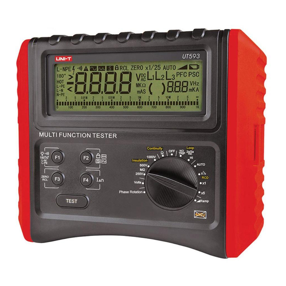
UT593/595 OPERATING MANUAL UT593/595 OPERATING MANUAL Mark on the instrument indicates that for safe operation of this instrument, users shall operate Notice the instrument according to the relevant content in this manual. Before resistance measurement, the circuits to be tested must be totally discharged and shall be 1. - Page 7 (SEE FIG. 1 AND FIG. 2) Only for reference Precision 1. LCD display 2. Function key F1, F2, F3, F4 <Test indices for phase sequence rotation of UT593/UT595> 3. Test key 4. Rotary switch Scope of applied voltage Three-phase AC voltage 100V~440V, frequency: 45Hz~65Hz;...
-
Page 8: Rotary Switch
UT593/595 OPERATING MANUAL UT593/595 OPERATING MANUAL V.ROTARY SWITCH VII. GROUNDING CONTINUITY MEASUREMENT (SEE FIG. 3 FOR CONNECTION DIAGRAM) 1. Phase-sequence measurement; 2. Voltage/frequency measurement; 3. 250V insulation resistance measurement; 4. 500V insulation resistance measurement; 5. 1000V insulation resistance measurement; 6. Measurement of maximum 200mA grounding continuity 7. -
Page 9: Insulation Resistance Measurement
UT593/595 OPERATING MANUAL UT593/595 OPERATING MANUAL VIII. INSULATION RESISTANCE MEASUREMENT Selection and operation of function keys F1-F4 is shown below: (FOR CONNECTION DIAGRAM, SEE FIG. 4) Buzzer and backlight Test lock ZERO Not used Instructions on key operation: Press and hold F1 for about 2 seconds to open and close the backlight; press and release F1 to open and close 20 Ù... -
Page 10: Voltage/Frequency Measurement
UT593/595 OPERATING MANUAL UT593/595 OPERATING MANUAL needed, press F2 to start TEST lock measurement function; at the same time, the LCD displays Notice: the symbol of lock. In this case, you only need to press and release the Test key to start long- Prior to test, ensure that the circuit to be test is not live. -
Page 11: Phase Sequence And Phase Loss Measurement
UT593/595 OPERATING MANUAL UT593/595 OPERATING MANUAL X. PHASE SEQUENCE AND PHASE LOSS MEASUREMENT Make the rotary switch point to Volts: According to connection method 1/2, conduct correct wiring, i.e. voltage/frequency measurement connection method (Fig. 5) 1: (SEE FIG. 6 FOR CONNECTION DIAGRAM) (1). -
Page 12: Measurement Of Fault Loop Circuit Impedance/ Fault Expected Short-Circuit Current
UT593/595 OPERATING MANUAL UT593/595 OPERATING MANUAL Selection and operation of function keys F1-F4 is shown below: Buzzer and backlight Not used Not used Not used Instructions on key operation: Press and hold F1 for about 2 seconds to open and close the backlight;... -
Page 13: Measurement Of Line Circuit Impedance/Expected Short-Circuit Current
UT593/595 OPERATING MANUAL UT593/595 OPERATING MANUAL Selection and operation of function keys F1-F4 is shown below: XII. MEASUREMENT OF LINE CIRCUIT IMPEDANCE/EXPECTED SHORT-CIRCUIT CURRENT (SEE FIG. 7, FIG. 8 AND FIG. G FOR Buzzer and backlight Not used Not used... -
Page 14: Automatic Rcd Sequence Test
UT593/595 OPERATING MANUAL UT593/595 OPERATING MANUAL Selection and operation of function keys F1-F4 is shown below: 3. You must ensure that neutral wire end of the power socket is reliably connected; in case poor connection or no connection of the neutral wire end of the power socket, L-N and N-PE symbols at the lower-left corner of LCD blink at the same time. -
Page 15: General Rcd Test
UT593/595 OPERATING MANUAL UT593/595 OPERATING MANUAL 5. This kind of measurement is conducted under high-voltage state; much attention shall be Note: The set leakage current value varies with the multiple. The specific multiple is given to personal safety. corresponding with leakage current, as shown in the following table: XIV. -
Page 16: T Est Of Rcd Tripping Action Trigger Current
UT593/595 OPERATING MANUAL UT593/595 OPERATING MANUAL Note: The set leakage current value varies with the waveform. The specific waveform is XV. TEST OF RCD TRIPPING ACTION TRIGGER CURRENT (SEE FIG. 7) corresponding with leakage current, as shown in the following table: Make the rotary switch point to Ramp test item in RCD. -
Page 17: Replace Battery
UT593/595 OPERATING MANUAL UT593/595 OPERATING MANUAL XVI. REPLACE BATTERY Danger In order to avoid the possible electric shock, remove the lead from the instrument in replacing the battery. Notice Don't use the old and new batteries together. Note the polarity of the battery in installation of it.
Need help?
Do you have a question about the UT593 and is the answer not in the manual?
Questions and answers