Table of Contents
Advertisement
Quick Links
INSTALLATION AND OPERATION MANUAL
MANUAL DE INSTALACIÓN Y FUNCIONAMIENTO
INSTALLATIONS- UND BETRIEBSHANDBUCH
MANUEL D'INSTALLATION ET DE FUNCTIONNEMENT
MANUALE D'INSTALLAZIONE E D'USO
HC-A64BNP
MANUAL DE INSTALAÇÃO E DE FUNCIONAMENTO
BRUGER- OG MONTERINGSVEJLEDNING
INSTALLATIE- EN BEDIENINGSHANDLEIDING
HANDBOK FÖR INSTALLATION OCH ANVÄNDING
ΕΓΧΕΙΡΙΔΙΟΕΓΚΑΤΑΣΤΑΣΗΣΚΑΙΛΕΙΤΟΥΡΓΙΑΣ
Advertisement
Table of Contents

Related Manuals for Hitachi HC-A64BNP


Summary of Contents for Hitachi HC-A64BNP
- Page 1 INSTALLATION AND OPERATION MANUAL MANUAL DE INSTALAÇÃO E DE FUNCIONAMENTO MANUAL DE INSTALACIÓN Y FUNCIONAMIENTO BRUGER- OG MONTERINGSVEJLEDNING INSTALLATIONS- UND BETRIEBSHANDBUCH INSTALLATIE- EN BEDIENINGSHANDLEIDING MANUEL D’INSTALLATION ET DE FUNCTIONNEMENT HANDBOK FÖR INSTALLATION OCH ANVÄNDING ΕΓΧΕΙΡΙΔΙΟΕΓΚΑΤΑΣΤΑΣΗΣΚΑΙΛΕΙΤΟΥΡΓΙΑΣ MANUALE D’INSTALLAZIONE E D’USO HC-A64BNP...
- Page 3 Specifikationerna i den här handboken kan ändras utan föregående meddelande för att HITACHI ska kunna leverera de senaste innovationerna till kunderna. Vi på Hitachi gör allt vi kan för att se till att alla specifikationer stämmer, men vi har ingen kontroll över tryckfel och kan därför inte hållas ansvariga för den typen av fel.
- Page 4 C A U T I O N This product shall not be mixed with general house waste at the end of its life and it shall be retired according to the appropria- ted local or national regulations in a environmentally correct way. Due to the refrigerant, oil and other components contained in Air Conditioner, its dismantling must be done by a professional installer according to the applicable regulations.
- Page 5 DANgER – Hazards or unsafe practices which COULD result in severe personal injuries or death. PElIgRO – Riesgos o prácticas poco seguras que PODRÍAN producir lesiones personales e incluso la muerte. gEFAhR – Gefährliche oder unsichere Anwendung, die zu schweren Körperverletzungen oder zum Tod führen kann. DANgER –...
-
Page 7: Table Of Contents
Contents Contents Contents _______________________________________________________________ 5 general Data ______________________________________________________ 6 Installation ________________________________________________________ 7 2.1. Safety Summary _______________________________________________ 7 2.2. Dimensional Data ______________________________________________ 7 2.3. Component List _______________________________________________ 8 2.4. Names of Parts ________________________________________________ 8 2.5. Servicing Space _______________________________________________ 10 2.6. Installation Procedure ___________________________________________ 10 2.6.1. -
Page 8: General Data
General Data 1. general Data The hardware specification for the HC-A64BNP is shown in Table 1.1, and the communication specification is shown in Table 1.2 and 1.3. Table 1.1 Specification for HC-A64BNP Hardware Item Specifications Power supply AC 220-240V 50/60Hz... -
Page 9: Installation
Installation 2. Installation 2.1. Safety Summary DANgER Perform the installation work according to this installation manual certainly. If performed wrong installation, it will cause an electrical shock, fire and injure by failed the system. CAUTION Do not install the HC-A64BNP and connect at the following places. If installed, it will cause a fire, and results a deformation, corrosion and damage. – Where generation, flowing, staying or leaking of flammable gas is detected. – Where there is oil vapor and the oil is dispersed. – Where the hot springs are near (in a sulfuric environment). Do not install the HC-A64BNP and cable at the following places. If installed, it will cause corrosion. – Where the sea is near (In the salty environment). – An acid or alkaline environment. – Where there is a lot of humidity air. Do not install the HC-A64BNP and conect at the following places. If installed, it will cause a malfunction and failure. – Where adapter will be exposed direct sunlight. – Where the temperature is extremely hight. – Where there adapter may be wet. – Where there is poorly ventilated place. Ensure that the installation place is strong enough. If not strong enough, the HC-A64BNP may fall down on you. Do not install the HC-A64BNP where the electromagnetic wave is directly radiated to the electrical parts. Do not install the HC-A64BNP within approximately 3 meters from strong electromagnetic wave radiators such as medical equipment. CAUTION This appliance must be used only by adult and capable people, having received the technical information or instructions to handle properly and safely this appliance. -
Page 10: Component List
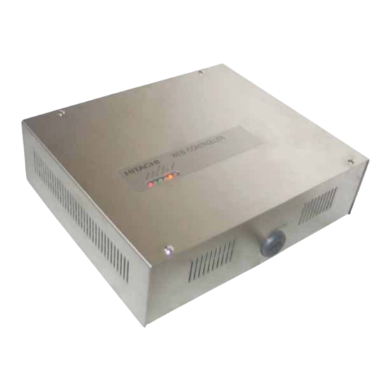
Installation 2.3. Component list When unpacking the HC-A64BNP, check that it has not suffered damage during transport. Components: - HC-A64 BNP - Installation manual PMML0161 A 2.4. Names of Parts The name of each part for the HC-A64BNP is shown in Fig.2.1 and 2.2. - Page 11 Name of Parts for Terminals and Switch Setting Following figure shows the HC-A64BNP without the upper cover. For connecting method for each terminal refer to the section 2.7, and for setting DSW refer to chapter 3 DSW for H-LINK/H-LINKII Circuit (SW3)
-
Page 12: Servicing Space
Keep the service space for the HC-A64BNP as shown in next figure 2.6. Installation Procedure In this clause, the installation method from the HC-A64BNP installation to the power ON (Test running) is described. The installation procedures are show in the following table. -
Page 13: Vertical Installation (On The Wall)
Installation 2.6.1. vertical Installation (On the Wall) (a) When installing the HC-A64BNP vertically (on the Wall), install it by keeping the connectors at the upper side. Install the HC-A64BNP as the connector surface is upper side INCORRECT CORRECT INCORRECT (b) Remove all of the rubber stands (4 pcs.). -
Page 14: Electrical Wiring
– Do NOT modify the inner system of the HC-A64BNP. It will cause a malfunction. 2.7.1. Electrical Wiring Procedure (1) The following electrical wiring work is required for the HC-A64BNP. - Power Supply Wiring - Transmission Line between HC-A64BNP and Air Conditioning. - Transmission Line (LAN) between HC-A64BNP and BMS. (2) Connection Procedures... -
Page 15: Electrical Wiring Connection
– When using the shielded cable, perform the grounding work according to the local codes and regulations. In Australia, connect the both ends of the shielded pair cable to the earth as shown below. Wires Shielded Twist Shield Earth Pair Cable – Before opening the top cover of the HC-A64BNP, turn OFF the power supply for UPS. And before electrical wiring work, ensure that the power supply of UPS is turned OFF. Unless UPS power is turned OFF, the current is kept supplied to the terminals and switch for the HC-A64BNP, which can cause electric shock when touched. – The HC-A64BNP has the backup system function. To realize the backup function, the “POWER LED” will stay lit for 30 seconds after power shuts down. Please make sure that “POWER LED” is OFF upon wiring.. 2.7.2. Electrical Wiring Connection (1) Before performing the electrical wiring connection, shut down the power supply of UPS and the other control system. - Page 16 Installation Note: Do NOT remove the cover for unused connector. If removed, it may cause malfunction. Table 2.7.2 Electrical Wiring Connection Procedures Type. Other End for Electrical Wiring Connection Procedure Remarks Connection Twist the power source Twist 1 time Connect by Circle Terminal line and grounding line around Ring Tightening Torque: 0.5N.m Uninterruptible around the same ring core Core.
-
Page 17: Operation
The example for the system configuration with the HC-A64BNP is shown next figure. This Installation and Operations Manual is only for HC-A64BNP. As for the other equipment of system in details, refer to the operation manual with each equipment. -
Page 18: Configuration
– Before turning ON the power, check to ensure that the insulating resistance between the power supply terminals and the grounding line is 1MΩ or more with DC500V. If it is less than 1MΩ, do NOT turn ON the power supply for insulation failure. – Do NOT operate the packaged air conditioner for checking the wiring connection until the test running preparation have been completed. – If it is occurred the abnormal accident as the smoke and fi re, shut down the power supply immediately). 3.1.1. Factory Setting Switch setting is not required for HC-A64BNP because the factory setting is ready to work. The switch setting at factory is shown. Factory Switch Usage Remarks Setting ON: Normal operation Mode (Other pins ar all OFF) -
Page 19: Servicing Setup
“ERROR” indicator flickers in every 1 or 3 seconds.) (2) As for the procedure after turning ON the HC-A64BNP again, the general flowchart of the test running is shown in the following figure. And as for the operation and verification procedure of the BACnet® simulator, refer to the operation manual for the BACnet®... -
Page 20: Led Activation In Normal And Abnormal Condition
Operation Test Running START Control Transmission to Packaged Air Conditioner Confirm to transmit the packaged air conditioner from the HC-A64BNP Check Monitor Display Condition Confirm the packaged air conditioner condition at the display. Test Running END General Flowchart of Test Running. - Page 21 Operation Contents for ERROR lED and 7-Segment lED Display ¡ Priority Cause for ERROR lED and Cause for ERROR lED and ERROR 7-Segment Order Condition 7-Segment lED ON 7-Segment lED OFF for lED Indication Abnormal In Case of Detected Abnormality in In Case of Normal in Writing Software Start- Writing Software...
-
Page 22: Self-Checking Mode
(1) Turn OFF the power supply of the HC-A64BNP. (2) Before performing the self-checking mode, disconnect the cables among the HC-A64BNP, packaged air conditioner and BMS. (3) Set OFF all pins of the option DSW (SW2) and turn ON the power supply. (Refer to No.1 of table in section 3.1.2 Servicing setup) (4) The self-checking mode is started. -
Page 23: Troubleshooting
Is the power supply of UPS turned ON? Turn ON the power supply of UPS. Is the power supply of the HC-A64BNP turned ON? Turn ON the power supply of the HC-A64BNP Is the value of the power supply voltage normal? Measure the voltage of UPS power supply. - Page 24 Indication Indication 1 Flickered per 3 seconds Is the HC-A64BNP connected to H-LINK / H-LINKII? Connect the HC-A64BNP to H-LINK / H-LINKII. Are all of packaged air conditioners connected to Power ON all of packaged air conditioners HC-A64BNP powered ON? connected to HC-A64BNP.
-
Page 25: Initialization For Ip Address Setting
Procedure (1) Remove the upper cover of the HC-A64BNP and set ON No. 1 and 8 pins of the option DSW (SW2) as shown in below figure. The normal operation mode setting is only No. 1 pin ON, therefore set No. 8 ON for the option DSW (SW2). - Page 28 PMML0161A rev.1 - 11/2011 - P5414431(Q) Printed in Spain...
Need help?
Do you have a question about the HC-A64BNP and is the answer not in the manual?
Questions and answers