
Related Manuals for Gehl Dynalift DL Series


Summary of Contents for Gehl Dynalift DL Series
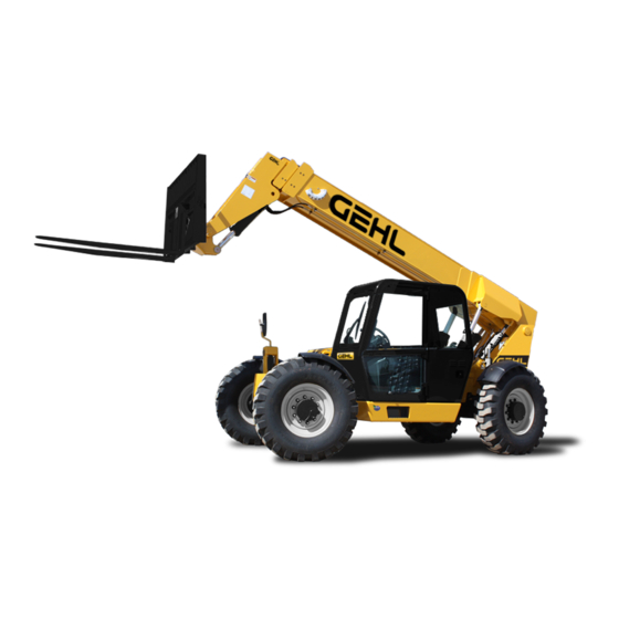
- Page 1 DL SERIES Form No. 908478 ® ® Dynalift Revision D Telescopic Handlers © 2007 Gehl Company • All Rights Reserved • Printed in USA...
- Page 2 Dynalift Indicator and Operation Symbols ® Read Operator’s Parking Brake Horn Engine Start Ignition Switch ON Safety Manual Fasten Seat Belt Battery Fuse Engine Air Filter Engine Stop Hazard Flasher Volume Full Volume Half Full Volume Empty Diesel Fuel Fuel Low Head Lights Transmission Hydraulic Oil...
-
Page 3: Table Of Contents
® ® Telescopic Handler Model and Serial Numbers below. Refer to these numbers when inquiring about parts or service from your Gehl dealer. The model and serial numbers for this machine are on a decal located inside the operator’s station. -
Page 4: Introduction
A storage pocket in the back of the seat is provided for storing the Operator’s Manual. After using the manual, please return it to the pocket and keep it with the unit at all times! If this machine is resold, GEHL Company rec- ommends that this manual be given to the new owner. - Page 5 Identification (DL-10H Shown) Dash Indicators Operator’s and Controls Side Panel Stabilizing ROPS/FOPS Seat and Controls Cylinder Boom Angle Indicator Attachment Tool Access Door with Rear Storage Dynattach® Tilt Lights and Compartment Quick-Attach Cylinder Access Door Backup Alarm Engine Air Rear View Telescopic Precleaner Mirror...
-
Page 6: Specifications
Chapter 2 SELECT-A-BOOM SPECIFICATIONS Lifting Performance DL-8L/44: 3’-0” (914 mm) DL-8H/42: 1’-8” (508 mm) DL-8L/44: 2’-9” (838 mm) DL-8H/44: 3’-4” (1016 mm) Maximum lift capacity: DL-8H/44: 2’-3” (686 mm) DL-10L/44: 3’-0” (914 mm) DL-6/40: 7000 lbs. (3171 kg) DL-10L/44: 2’-9” (838 mm) DL-10H/44: 3’-4”... - Page 7 General Dimensions Transmission Monitoring alarms: Low oil pressure, low accumulator Based on standard machine equipped Type: Clark Powershift T16000 charge with listed tires, 48” (1.2 m) masonry Speeds: 4 fwd / 2 rev Visual indicators: carriage and 48” (1.2 m) pallet forks. Torque converter: Boom angle, boom extension, Single-stage, dual-phase...
- Page 8 Hydraulic System Type: Open-center Pump: Dual-section gear type Displacement / revolution: Front: 1.77 cu. in. (29 cc) Rear: 2.19 cu. in. (36 cc) Flow @ 2500 RPM: Front: 19 gpm (72 L/min) Rear: 24 gpm (90 L/min) Main relief pressure: 3000 psi (207 bar) Aux.
-
Page 9: Checklists
Chapter 3 CHECKLISTS PRE-DELIVERY I acknowledge that the pre-delivery procedures were per- formed on this unit as outlined above. The following Checklist is an important reminder of the inspections that MUST be made before delivering the Telescopic Handler to the customer. Check off each item Dealership’s Name after the prescribed action is taken. -
Page 10: Intentionally Blank
INTENTIONALLY BLANK (To be removed as Dealer’s file copy) 908478/DP0307 PRINTED IN U.S.A. - Page 11 Chapter 3 CHECKLISTS PRE-DELIVERY I acknowledge that the pre-delivery procedures were per- formed on this unit as outlined above. The following Checklist is an important reminder of the inspections that MUST be made before delivering the Telescopic Handler to the customer. Check off each item Dealership’s Name after the prescribed action is taken.
-
Page 12: Safety
Chapter 4 SAFETY The above Safety Alert Symbol means ATTENTION! Gehl Company ALWAYS takes the operator’s safety ALWAYS BE ALERT! YOUR SAFETY IS into consideration when designing its machinery, and INVOLVED! It stresses an attitude of safety aware- guards exposed moving parts for his/her protection. - Page 13 SAFETY Additional Safety Reminders WARNING User/operator safety practices, as established by industry standards, are included in this Operator’s Manual and intended to promote safe operation of U.S. OSHA regulations require employers in general industry and the construction, ship- the machine. These guidelines do not, of course, yard and cargo-handling industries (excepting preclude the use of good judgment, care and com- mon sense that may be necessary for the particular...
- Page 14 SAFETY outward and upward distances. ALWAYS be aware Walk around the machine and warn all personnel of load weights prior to attempting lift and place- who may be servicing the machine or who are in ment. the machine’s path prior to starting. DO NOT start until all personnel are clearly away from the DO NOT exceed the machine’s rated operating machine.
- Page 15 To ensure continued safe operation, replace dam- injury or gangrene may result. aged or worn-out parts with genuine Gehl service ALWAYS wear safety glasses with side shields parts BEFORE using this equipment.
- Page 16 SAFETY Safety Guards and Warning Devices MANDATORY WORK PLATFORM This machine is fitted with a Roll-Over Protective SAFETY RULES Structure (ROPS) and Falling Object Protective Structure (FOPS) in accordance with industry stan- 1. The work platform must comply with dards. It is intended to offer protection to the oper- ANSI/ITSDF Standard B56.6-2005, Sec.
- Page 17 SAFETY 14. Be sure the path of platform travel is clear of haz- WARNING ards, such as scaffolds, electrical wires and over- head obstructions. 15. The operator must keep hands and feet clear of Use ONLY an approved work platform for ele- controls that are not in use.
-
Page 18: Wireless Remote Battery Replacement
SAFETY the user. 5. Protection for personnel in their normal working position on the platform from moving parts of the forklift that may present a hazard. 6. Information prominently indicated on the plat- form: a. maximum work load including personnel and Remote equipment, and Shutdown... - Page 19 SAFETY 10. Lanyards, when provided, shall be arranged so as not to cause a tripping hazard. 11. Body harnesses, when provided, should have a width of at least 1.75 inches (44 mm). 12. Structural safety factor - All load supporting struc- tural elements of the work platform shall have a structural safety factor of not less than 2-to-1 based on the minimum yield strength of the materials...
- Page 20 SAFETY L70306 L70307 L65926 L70307 L70306 100359 105099 100359 L65926 105099 908478/DP0307 PRINTED IN U.S.A.
- Page 21 SAFETY 101506 L65928 L65932 L65928 101506 L65932 L70238 L70238 PRINTED IN U.S.A. 908478/DP0307...
- Page 22 SAFETY L65927 L65927 L65927 072798 L65927 L70305 072798 L70305 908478/DP0307 PRINTED IN U.S.A.
- Page 23 SAFETY L65928 L65928 L65927 L65927 L65927 L65933 L65927 L65933 PRINTED IN U.S.A. 908478/DP0307...
- Page 24 SAFETY PWP Safety Decals L71555 102969 L71554 L71700 L71554 L71554 L71700 102969 L71555 908478/DP0307 PRINTED IN U.S.A.
- Page 25 NOTES PRINTED IN U.S.A. 908478/DP0307...
-
Page 26: Indicators And Controls
BEFORE operating it. This Gehl machine is designed and intended to be used ONLY with WARNING a Gehl Company attachment tool, or a Gehl Company approved accessory or referral Read and thoroughly understand all safety attachment tool. Gehl Company cannot be... - Page 27 Right Bank Switches Switches have graphic symbols to indicate function and effect. The following mode descriptions start with the first switch on the left. Cold Starting Option: This switch acti- vates the injection of an ether agent for faster engine start in cold weather. Clutch Cutout: When activated, this switch allows faster engine acceleration and power to the hydraulics system with-...
- Page 28 NOTE: ing selector mode must be changed. Only machines equipped with the engine shutdown protection have this switch. Axle Align: Allows the operator to check for straight tracking of the rear wheels. This switch must be pressed within 30 seconds to pre- When activated, a green lamp lights on the vent undesired shutdown of engine.
- Page 29 to the right or left to turn the machine in the direction Alternator Lamp: This display is of wheel turn action. located in the lower left corner of the top panel. It indicates the con- dition of the electrical charging Horn Button: With the keyswitch on, press the center system.
-
Page 30: Right Side Panel
Travel Lever slowly 10 to the left or right to level the frame and boom in relation to the ground. Located on the left side of the console, this lever is Frame Angle Indicator: Located in front of the oper- used to change travel direction (forward or reverse) ator on the ROPS upper cross tube. - Page 31 WARNING WARNING When tilting or operating the auxiliary When tilting the attachment or operating the hydraulics with a rocker switch type of joy- auxiliary hydraulics with a two button type of stick handle, to avoid any unexpected action joystick handle, to avoid any unexpected be sure the joystick is at the “neutral”...
- Page 32 Pulling on the trigger increases the speed of the attach- dle also incorporates a manually-adjusted speed con- ment tilt and auxiliary hydraulic functions. trol to allow changing factory-set speeds. This speed adjustment is accomplished through the adjustment of the pilot pressure apply valves located in the rear com- partment of the machine.
- Page 33 SAFETY SHUTDOWN PROCEDURE. DO NOT DO NOT travel with the outriggers extended. attempt repairs. Instead call your Gehl dealer for assistance. Adequate clearance is required for the retract- ed outriggers when traveling through door- The truss boom and winch attachment tools ways or along narrow pathways.
-
Page 34: Additional Indicators
Suspension Seat Option: This seat has a knob under Coolant Level: The coolant can be checked and added the front of the seat to adjust the suspension. Turn the through the radiator cap in the engine/power train com- knob to the right for a softer ride, and to the left for a partment. -
Page 35: Side Rear View Mirror
Contact your Gehl dealer for specifications and order- ing information. ACCESSORIES Gehl also offers a range of special accessories for this machine. Contact your Gehl dealer for specifications and ordering information. NOTE: All accessories are field-installed unless otherwise noted. -
Page 36: Operation And Adjustments
Chapter 6 OPERATION AND ADJUSTMENTS GENERAL INFORMATION BEFORE STARTING ENGINE Before starting the engine and running the machine, CAUTION refer to the Indicators and Controls chapter and famil- iarize yourself with the various operating controls, BEFORE starting the engine and operating the indicators and safety features. -
Page 37: First-Time Operation
20° F (-7° C) or engine speed while the machine is in motion. lower. See your Gehl dealer for recommended heater. DO NOT overspeed the engine when down shifting. If prevailing temperature is 40° F (4° C) or below, it... -
Page 38: Parking Brake
The Telescopic Handler boom nose will accept two connect hoses to the quick-connect connectors on ® types of Gehl attachment devices: 1.)The Dynattach the boom nose. quick-attach system, which has a quick-release hookup and locking mechanism for mounting framing and masonry type attachment tools to the boom nose, and ®... - Page 39 LOCK LEVER Dynacarrier Quick-attach System ® Attachment Tool Shown Attaching-Dynacarrier ® Quick-attach Unlocked for Release from System ® Dynattach System To pick up a bucket or material handling carriage tool, ® Dynattach System Detaching Detail proceed as follows: Detaching-Dynattach Quick-attach ®...
- Page 40 Use proper grab handles, NOT the steering Modifications, alterations to, or use of attach- wheel or control levers as handholds when ment tools not authorized by Gehl Company mounting or dismounting. can void the warranty and cause machine damage, and may result in serious personal NEVER operate the machine with safety injury or death.
-
Page 41: Traffic Flow Patterns
Grade and Slope Precautions of the wheels, the FRAME MUST BE LEVEL, as indicated by the frame angle indicator on the The Telescopic Handler complies with industry stabil- ROPS crossmember. The attachment tool MUST ity tests requirements and is stable when properly oper- be maintained at the “carry”... - Page 42 The backup alarm automatically sounds when the trav- trol a small amount away from neutral. Then, after el lever is in Reverse. Care should be taken when down movement has started, the control can be eased to full shifting or reversing because damage to the transmis- movement.
- Page 43 BOOM EXTENSION MARKERS REFERENCE DISTANCE LOAD IS EXTENDED Typical Load Zone Chart Example: Load Capacity and Reach The operator, using a standard carriage attachment tool without outriggers, wants to raise a The machine has flip-charts in the operator’s station 3000 lb. load 20 feet high, and can only get to within that provide, at a glance, the capacity limits at various 15 feet of the load placement point.
- Page 44 LIFTING ATTACHMENT TOOL Load Elevation and Placement APPLICATIONS For ground level load placement, be sure the area under the load and around the machine is clear of Picking Up the Load equipment and personnel. Lower the load to the ground, tilt the forks to the horizontal position, and Inspect the load before picking it up.
- Page 45 5. On 55’ models, the remote shutdown switch is wireless-operated. Secure the remote shutdown switch to the PWP using the strap attached to the switch, as shown below. Retaining 3. Secure the forks from pivoting upward in case the PWP is lowered onto an obstruction. This can be accomplished by using the chain supplied with the Remote PWP, to secure the lower portion of the PWP to the...
- Page 46 NOT attempt to bring down the boom or make brakes and press the bottom of the PWP System rock- repairs. Call your Gehl dealer immediately. er switch. The system is de-activated when the lamp in the PWP System rocker switch is off.
-
Page 47: Suspended Loads
SUSPENDED LOADS Table of Common Materials & Densities Material Density Density DO NOT exceed the Telescopic Handler capacity as in (lb/yd in (kg/m equipped for handling suspended loads. Only lift the Ashes 945-1350 560-800 load vertically and NEVER drag it horizontally. Use Brick-common 3024 1795... - Page 48 When the bucket is filled, back the machine away from Dumping the Load onto a Pile the material and roll back the bucket before proceeding to the dumping area. Carry the loaded bucket as low as possible until reach- ing the pile. Slowly stop forward motion, then raise Digging and extend the boom high enough so that the bucket Loose Materials...
-
Page 49: Transporting Between Jobsites
Then travel slowly forward. With the bucket in this NOTE: ALWAYS follow ALL state and local reg- position, material can flow over the cutting edge and ulations regarding the operation of equipment on collect inside the bucket. or across public highways. Whenever there is an appreciable distance between jobsites, or if dri- Leveling with a Bucket ving on public highways is prohibited, transport... -
Page 50: Theft Deterrents
THEFT DETERRENTS or trailer bed with NO step between the bed and the ramps. Gehl Company has recorded all major component part numbers and serial numbers. Users should take as 3. The incline of the ramps MUST be less than 15 many of the following actions as possible to discour- degrees (ramp length MUST be at least 16 feet (4.9... -
Page 51: General Information
Chapter 7 LUBRICATION GENERAL INFORMATION Hydraulic System Reservoir Use a Mobil DTE 15M, or an equivalent that WARNING contains anti-rust, anti-foam and anti-oxidation additives and conforms to ISO VG46. Capacity: NEVER lubricate or service this unit when any 45 Gallons (170 Liters) part of the machine is in motion. - Page 52 Every 50 Hours (or weekly) with mechanical throttle Refer to the illustration below for locations. Oil Filter Element Gehl P/N L99420 1. Tilt Cylinder Pins (2 ea.) Fuel Filter Element Gehl P/N L98978 2. Frame Leveling Cylinder Pins (2 ea.) John Deere Engines 3.
-
Page 53: Service And Storage
All cylinders are approprietly designed Warranty repairs can only be done by a Gehl dealer. with particular strokes, diameters, checks and hose Dealers know what portions of the machine are cov-... -
Page 54: Electrical Components
Gehl dealer. WARNING ELECTRICAL COMPONENTS Tilt, lift, extend, and leveling cylinders have An electrical system schematic is provided, which counterbalance valves. These valves keep includes instrumentation, electrical components and hydraulic fluid from entering or exiting the switch connections. -
Page 55: Checking Fuel Filter
Block the tires. Turn off the master disconnect switch WARNING to shut off power from the battery, and remove the igni- tion key. Remove only guards or covers that provide needed access. Wipe away excess grease and oil. DO NOT smoke or allow any open flames in area while checking... - Page 56 CHECKING ENGINE OIL LEVEL oil fill tube cap. If the oil level is below the ADD mark, fill with the required amount of oil to bring the level to With the machine on level ground, and the engine the FULL mark. See the Lubrication chapter for the stopped for ten minutes or more, raise the engine hood type of oil to use.
- Page 57 USE the machine until the cause has been cor- and note the frame angle indicator movement. rected. Contact your dealer Gehl CHECKING GENERAL MACHINE OPERA- Company) for service information and parts. TION AND CONDITION Machine Position Are any decals missing or damaged? Are all guards,...
-
Page 58: 1000 Hours
Activation Tests De-activation Tests To test the PWP System activation logic: To test the PWP System de-activation logic: 1. Start the engine and press the PWP rocker switch 1. Turn the keyswitch to “OFF” and wait for the “ON.” engine to stop. Then turn the keyswitch back to “ON.”... -
Page 59: Changing Fuel Filter
CHECKING TRANSFER CASE OIL LEVEL Service Every 250 Hours or Quarterly Remove the oil level check plug. Oil should flow from the hole. If low, remove the breather cap located on the NOTE: Perform all other service requirements up front side of the transfer case. Fill with the proper oil to this point as well as the following: until oil flows from the check hole. -
Page 60: Changing Engine Oil And Filter
Diesel Fuel Injectors CHECKING THE BATTERY Whenever faulty or plugged fuel injectors are indicat- The battery furnished in the machine is a 12-volt, wet- ed, contact an authorized engine dealer. cell battery. Diesel Injection Pump Timing The top of the battery must always be kept clean. Clean the battery with a brush dipped in an alkaline solution Whenever injection pump timing or other injection (ammonia or baking soda and water). - Page 61 Jump Starting from the battery, fuel lines, and moving parts. NOTE: Twist the jumper cable clamps on the bat- If the battery becomes discharged or does not have tery terminals to ensure a good electrical connec- enough power to start the engine, use jumper cables tion.
- Page 62 pads should be replaced when their thickness is worn Two Front One Front One Rear Boom Chains Boom Chain down to 3/8” (9.5 mm). Boom Chain WARNING Failure to maintain proper slide pad clearance and thickness could cause damage to the 2nd Intermediate Inner Outer...
- Page 63 2. Remove and discard the oil filter. Wipe the sealing NOTE: Check the engine temperature lamp every surface on the transmission with a clean cloth. minute or two after coolant has been changed. Air Apply a thin coat of clean oil to the new oil filter pockets can form, and it may be necessary to refill gasket.
- Page 64 the outer element is replaced, unless the outer element NOTE: Keep spare elements on hand to eliminate is damaged or the inner element is visibly dirty. Along down time. with a daily check of the restriction indicator lamp, check that the air cleaner intake hose and clamps, and CHANGING AXLE DIFFERENTIAL the mounting bracket hardware are properly secure.
-
Page 65: Checking Exhaust System
Order replacement 2. Disconnect the suction hose and remove the sump belts from your Gehl dealer. strainer from inside the reservoir. Inspect the strainer. If it has any damage, holes, etc., it should CHECKING EXHAUST SYSTEM be replaced. - Page 66 6. If the ambient temperature (at any time during the IMPORTANT: Hydraulic fluid and filters should be replaced any time contamination is present before storage period) is expected to drop below freezing, the normally scheduled change. make sure the engine coolant is either completely drained from the radiator and engine block or that CHANGING TRANSFER CASE OIL the amount of anti-freeze in it is adequate to keep...
- Page 67 PWP System remote shut- System remote shutdown switch. down switch. System level sensor Contact your Gehl dealer for unplugged or faulty. assistance. PWP System switch lamp flash- es when switch is turned “OFF.” PWP System is not de-activated. With engine running, apply ser-...
-
Page 68: Decal Locations
Chapter 9 DECAL LOCATIONS GENERAL INFORMATION PAINT FINISH Use this list to order paint for refinishing: CAUTION 184768 One Gal. Yellow 167789 6 (12-oz. Spray Cans) Yellow ALWAYS read and follow the safety precau- 167758 One Gal. Charcoal Gray tions and information shown on decals. If any 906318 6 (12 oz. - Page 69 DECAL LOCATIONS - OPERATOR’S STATION REF. DESCRIPTION DL-6 DL-8 DL-10 DL-12 WARNING - SEAT BELT AND PARK BRAKE 101506 101506 101506 101506 IGNITION 101507 101507 101507 101507 DANGER - PERSONNEL INJURY (units w/o PWP) L65928 L65928 L65928 L65928 WARNING - CARRY LOAD LOW 093475 093475 093475...
- Page 70 DECAL LOCATIONS - FRAME and BOOM REF. DESCRIPTION DL-6 DL-8 DL-10 DL-12 GEHL, 6.38” (solid color decal) 101466 101466 101466 101466 GEHL, 6.75” (3-D style decal) 184069 184069 184069 184069 GEHL, 8.00” (solid color decal) 101467 101467 101467 101467 GEHL, 8.00” (3-D style decal)
- Page 71 DANGER - HANDS OUT L70305 L70305 L70305 L70305 GEHL, 2.0” (solid color decal) 101468 101468 101468 101468 GEHL, 2.0 “ (3-D style decal) 102026 102026 102026 1020026 GEHL, 5.25” (solid color decal) L70464 L70464 L70464 L70464 GEHL, 5.00” (3-D style decal)
- Page 72 DECAL LOCATIONS - PWP EQUIPPED UNITS REF. DESCRIPTION DL-6 DL-8 DL-10 DL-12 PWP SWITCH INSTRUCTION 102969 102969 102969 102969 PERSONNEL LIFT L71554 L71554 L71554 L71554 WORK PLATFORM RULES L71555 L71555 L71555 L71555 PERSONNEL LIFT SAFETY RULES L71700 L71700 L71700 L71700 PWP LOAD ZONE CHART See Note See Note...
- Page 73 INTENTIONALLY BLANK PRINTED IN U.S.A. 908478/DP0307...
-
Page 74: Maintenance
Chapter 10 MAINTENANCE This Maintenance Interval Chart was developed to match the Service and Storage chapter of this manual. Detailed information on each Service Procedure may be found in the Service and Storage chapter. A Maintenance Log fol- lows the Maintenance Interval Chart for recording the service procedures performed. Recording the 10 Hour (or Daily) service intervals would be impractical and therefore is not recommended. -
Page 75: Maintenance Log
MAINTENANCE INTERVAL CHART (CONT.) SERVICE PROCEDURE Every 250 Every 1000 Every 2000 Hours or Hours or Hours or Quarterly Yearly Two Years Check Boom Slide Pads Wear and Clearance Check Personnel Work Platform System Change Transmission Oil and Filter Check Alternator and Fan Belt Condition Change Radiator Coolant Change Hydraulic Return Filter Element Change Primary Air Filter Element... - Page 76 MAINTENANCE LOG Date Hours Service Procedure 908478/DP0307 PRINTED IN U.S.A.
- Page 77 MAINTENANCE LOG Date Hours Service Procedure PRINTED IN U.S.A. 908478/DP0307...
-
Page 78: Electrical Schematics
Electrical Schematic w/o PWP System (For serial numbers listed below with 2-button or rocker switch joystick) DL-6H ..thru S/N 20299 DL-10H ..thru S/N 40135 DL-6L ..thru S/N 25351 DL-10L ..thru S/N 45097 DL-8H . - Page 79 Electrical Schematic w/o PWP System (Continued from previous page) “A” “B” “C” “D” “E” “F” “G” “H” “I” “J” “K” PRINTED IN U.S.A. 908478/DP0307...
- Page 80 Electrical Schematic with PWP System (For serial numbers listed below with 2-button or rocker switch joystick) DL-6H ..S/N 20300 thru 20576 DL-10H ..S/N 40136 thru 40261 DL-6L ..S/N 25352 thru 25498 DL-10L .
- Page 81 Electrical Schematic with PWP System (Continued from previous page) “A” “B” “C” “D” “E” “F” “G” “H” “I” “J” “K” elcpwpf2.tif PRINTED IN U.S.A. 908478/DP0307...
- Page 82 Electrical Schematic with PWP System (For serial numbers listed below with 2-button or rocker switch joystick) DL-6H ..S/N 20577 thru 20823 DL-10H ..S/N 40262 thru 40498 DL-6L ..S/N 25499 thru 25615 DL-10L .
- Page 83 Electrical Schematic with PWP System (Continued from previous page) “A” “B” “C” “D” “E” “F” “G” “H” “I” “J” “K” PRINTED IN U.S.A. 908478/DP0307...
- Page 84 Electrical Schematic with PWP System (For serial numbers listed below with 2-button joystick) DL-6H ..S/N 20824 and Up DL-10H ..S/N 40499 and Up DL-6L ..S/N 25616 and Up DL-10L ..S/N 45185 and Up DL-8H .
- Page 85 Electrical Schematic with PWP System (Continued from previous page) “A” “B” “C” “D” “E” “F” “G” “H” “I” “J” “K” PRINTED IN U.S.A. 908478/DP0307...
- Page 86 Electrical Schematic with PWP System (For serial numbers listed below and with 4-button joystick) DL-6H ..thru S/N 20797 DL-10H ..thru S/N 40459 DL-6L ..thru S/N 25587 DL-10L ..thru S/N 45172 DL-8H .
- Page 87 Electrical Schematic with PWP System (Continued from previous page) “A” “B” “C” “D” “E” “F” “G” “H” “I” “J” “K” elcpwpf4.tif PRINTED IN U.S.A. 908478/DP0307...
- Page 88 Electrical Schematic with PWP System (For serial numbers listed below and with 4-button joystick) DL-6H ..S/N 20798 thru 20823 DL-10H ..S/N 40460 thru 40498 DL-6L ..S/N 25588 thru 25615 DL-10L .
- Page 89 Electrical Schematic with PWP System (Continued from previous page) “A” “B” “C” “D” “E” “F” “G” “H” “I” “J” “K” PRINTED IN U.S.A. 908478/DP0307...
- Page 90 Electrical Schematic with PWP System (For serial numbers listed below and with 4-button joystick) DL-6H ..S/N 20824 and up DL-10H ..S/N 40499 and up DL-6L ..S/N 25616 and up DL-10L .
- Page 91 Electrical Schematic with PWP System (Continued from previous page) “A” “B” “C” D” “E” “F” “G” “H” “I” “J” “K” PRINTED IN U.S.A. 908478/DP0307...
-
Page 92: Hydraulic Schematics
Hydraulic Schematic with PWP System (For serial numbers listed below with 2-button joystick) DL-6H ..thru S/N 20803 DL-10H ..thru S/N 40459 DL-6L ..thru S/N 25587 DL-10L ..thru S/N 45172 DL-8H . - Page 93 Hydraulic Schematic with PWP System (Continued from previous page) 3000 PSI 3900 PSI 3900 PSI 3000 PSI 2500 PSI 3900 PSI “A” 2500 PSI 3900 PSI 2500 PSI 2500 PSI “B” “C” 3200 PSI 40 PSI D” “E” “F” “G” PRINTED IN U.S.A.
- Page 94 Hydraulic Schematic with PWP System (For serial numbers listed below with 2-button joystick) DL-6H ..S/N 20804 and up DL-10H ..S/N 40460 and up DL-6L ..S/N 25588 and up DL-10L ..S/N 45173 and up DL-8H .
- Page 95 Hydraulic Schematic with PWP System (Continued from previous page) 3000 PSI 3900 PSI 3900 PSI 3000 PSI 2500 PSI “A” 2500 PSI 2500 PSI 2500 PSI “B” “C” 3200 PSI 40 PSI “D” “E” “F” “G” PRINTED IN U.S.A. 908478/DP0307...
- Page 96 Hydraulic Schematic with PWP System (For serial numbers listed below with 4-button joystick) DL-6H ..thru S/N 20803 DL-10H ..thru S/N 40459 DL-6L ..thru S/N 25587 DL-10L ..thru S/N 45172 DL-8H .
- Page 97 Hydraulic Schematic with PWP System (Continued from previous page) 3000 PSI 3900 PSI 3900 PSI 2500 PSI 3000 PSI 3900 PSI “A” 2500 PSI 3900 PSI 2500 PSI 2500 PSI “B” “C” 3200 PSI 40 PSI D” “E” “F” “G” PRINTED IN U.S.A.
- Page 98 Hydraulic Schematic with PWP System (For serial numbers listed below with 4-button joystick) DL-6H ..S/N 20804 and up DL-10H ..S/N 40460 and up DL-6L ..S/N 25588 and up DL-10L ..S/N 45173 and up DL-8H .
- Page 99 Hydraulic Schematic with PWP System (Continued from previous page) 3000 PSI 3900 PSI 3900 PSI 3000 PSI 2500 PSI 3900 PSI “A” 2500 PSI 3900 PSI 2500 PSI 2500 PSI “B” “C” 3200 PSI 40 PSI “D” “E” “F” “G” PRINTED IN U.S.A.
-
Page 100: Load Zone Charts
Select-A-Boom Load Zone Charts DL-6H / 40 Standard Carriage - Decal L70488 Rotate Carriage - Decal L70974 Select-A-Boom Load Zone Charts DL-6H / 40 12-Ft. Truss Boom - Decal L70535 15-Ft. Truss Boom - Decal L70550 908478/DP0307 PRINTED IN U.S.A. - Page 101 Select-A-Boom Load Zone Charts DL-6H / 40 1.3 Cu.-Yd. Bucket - Decal L70555 2.5 Cu.-Yd. Bucket - Decal L70532 Select-A-Boom Load Zone Charts DL-6H / 40 Winch - Decal L70997 Swing Carriage - Decal L71064 PRINTED IN U.S.A. 908478/DP0307...
- Page 102 Select-A-Boom Load Zone Charts DL-6H / 40 PWP - Decal L71711 Select-A-Boom Load Zone Charts DL-6L / 40 Standard Carriage - Decal L70498 Rotate Carriage - Decal L70977 908478/DP0307 PRINTED IN U.S.A.
- Page 103 Select-A-Boom Load Zone Charts DL-6L / 40 12-Ft. Truss Boom - Decal L70545 15-Ft. Truss Boom - Decal L70560 Select-A-Boom Load Zone Charts DL-6L / 40 1.3 Cu.-Yd. Bucket - Decal L70569 2.5 Cu.-Yd. Bucket - Decal L70542 PRINTED IN U.S.A. 908478/DP0307...
- Page 104 Select-A-Boom Load Zone Charts DL-6L / 40 Winch - Decal L70996 Swing Carriage - Decal L71065 Select-A-Boom Load Zone Charts DL-6L / 40 PWP - Decal L71745 908478/DP0307 PRINTED IN U.S.A.
- Page 105 Select-A-Boom Load Zone Charts DL-6H / 42 Standard Carriage - Decal L70770 Rotate Carriage - Decal L70980 Select-A-Boom Load Zone Charts DL-6H / 42 12-Ft. Truss Boom - Decal L70772 15-Ft. Truss Boom - Decal L70773 PRINTED IN U.S.A. 908478/DP0307...
- Page 106 Select-A-Boom Load Zone Charts DL-6H / 42 1.3 Cu.-Yd. Bucket - Decal L70774 2.5 Cu.-Yd. Bucket - Decal L70775 Select-A-Boom Load Zone Charts DL-6H / 42 Winch - Decal L70995 Swing Carriage - Decal L71062 908478/DP0307 PRINTED IN U.S.A.
- Page 107 Select-A-Boom Load Zone Charts DL-6H / 42 PWP - Decal L71743 Select-A-Boom Load Zone Charts DL-6L / 42 Standard Carriage - Decal L70780 Rotate Carriage - Decal L70982 PRINTED IN U.S.A. 908478/DP0307...
- Page 108 Select-A-Boom Load Zone Charts DL-6L / 42 12-Ft. Truss Boom - Decal L70782 15-Ft. Truss Boom - Decal L70783 Select-A-Boom Load Zone Charts DL-6L / 42 1.3 Cu.-Yd. Bucket - Decal L70784 2.5 Cu.-Yd. Bucket - Decal L70785 908478/DP0307 PRINTED IN U.S.A.
- Page 109 Select-A-Boom Load Zone Charts DL-6L / 42 Winch - Decal L70994 Swing Carriage - Decal L71063 Select-A-Boom Load Zone Charts DL-6L / 42 PWP - Decal L71744 PRINTED IN U.S.A. 908478/DP0307...
- Page 110 Select-A-Boom Load Zone Charts DL-6H / 44 Standard Carriage - Decal L70730 Rotate Carriage - Decal L70984 Select-A-Boom Load Zone Charts DL-6H / 44 12-Ft. Truss Boom - Decal L70732 15-Ft. Truss Boom - Decal L70733 908478/DP0307 PRINTED IN U.S.A.
- Page 111 Select-A-Boom Load Zone Charts DL-6H / 44 1.3 Cu.-Yd. Bucket - Decal L70734 2.5 Cu.-Yd. Bucket - Decal L70735 Select-A-Boom Load Zone Charts DL-6H / 44 Winch - Decal L70993 Swing Carriage - Decal L71060 PRINTED IN U.S.A. 908478/DP0307...
- Page 112 Select-A-Boom Load Zone Charts DL-6H / 44 PWP - Decal L71741 Select-A-Boom Load Zone Charts DL-6L / 44 Standard Carriage - Decal L70740 Rotate Carriage - Decal L70985 908478/DP0307 PRINTED IN U.S.A.
- Page 113 Select-A-Boom Load Zone Charts DL-6L / 44 12-Ft. Truss Boom - Decal L70742 15-Ft. Truss Boom - Decal L70743 Select-A-Boom Load Zone Charts DL-6L / 44 1.3 Cu.-Yd. Bucket - Decal L70744 2.5 Cu.-Yd. Bucket - Decal L70745 PRINTED IN U.S.A. 908478/DP0307...
- Page 114 Select-A-Boom Load Zone Charts DL-6L / 44 Winch - Decal L70992 Swing Carriage - Decal L71061 Select-A-Boom Load Zone Charts DL-6L / 44 PWP - Decal L71742 908478/DP0307 PRINTED IN U.S.A.
- Page 115 Select-A-Boom Load Zone Charts DL-8H / 42 Standard Carriage - Decal L70489 Rotate Carriage - Decal L70975 Select-A-Boom Load Zone Charts DL-8H / 42 12-Ft. Truss Boom - Decal L70536 15-Ft. Truss Boom - Decal L70551 PRINTED IN U.S.A. 908478/DP0307...
- Page 116 Select-A-Boom Load Zone Charts DL-8H / 42 1.3 Cu.-Yd. Bucket - Decal L70556 2.5 Cu.-Yd. Bucket - Decal L70533 Select-A-Boom Load Zone Charts DL-8H / 42 Winch - Decal L70991 Swing Carriage - Decal L70721 908478/DP0307 PRINTED IN U.S.A.
- Page 117 Select-A-Boom Load Zone Charts DL-8H / 42 PWP - Decal L71739 Select-A-Boom Load Zone Charts DL-8L / 42 Standard Carriage - Decal L70499 Rotate Carriage - Decal L70978 PRINTED IN U.S.A. 908478/DP0307...
- Page 118 Select-A-Boom Load Zone Charts DL-8L / 42 12 Ft.-Truss Boom - Decal L70546 15-Ft. Truss Boom - Decal L70561 Select-A-Boom Load Zone Charts DL-8L / 42 1.3 Cu.-Yd. Bucket - Decal L70570 2.5 Cu.-Yd. Bucket - Decal L70543 908478/DP0307 PRINTED IN U.S.A.
- Page 119 Select-A-Boom Load Zone Charts DL-8L / 42 Winch - Decal L70990 Swing Carriage - Decal L71059 Select-A-Boom Load Zone Charts DL-8L / 42 PWP - Decal L71740 PRINTED IN U.S.A. 908478/DP0307...
- Page 120 Select-A-Boom Load Zone Charts DL-8H / 44 Standard Carriage - Decal L70750 Rotate Carriage - Decal L70981 Select-A-Boom Load Zone Charts DL-8H / 44 12-Ft. Truss Boom - Decal L70752 15-Ft. Truss Boom - Decal L70753 908478/DP0307 PRINTED IN U.S.A.
- Page 121 Select-A-Boom Load Zone Charts DL-8H / 44 1.3 Cu.-Yd. Bucket - Decal L70754 2.5 Cu.-Yd. Bucket - Decal L70755 Select-A-Boom Load Zone Charts DL-8H / 44 Winch - Decal L70989 Swing Carriage - Decal L71057 PRINTED IN U.S.A. 908478/DP0307...
- Page 122 Select-A-Boom Load Zone Charts DL-8H / 44 PWP - Decal L71737 Select-A-Boom Load Zone Charts DL-8L / 44 Standard Carriage - Decal L70760 Rotate Carriage - Decal L70983 908478/DP0307 PRINTED IN U.S.A.
- Page 123 Select-A-Boom Load Zone Charts DL-8L / 44 12-Ft. Truss Boom - Decal L70762 15-Ft. Truss Boom - Decal L70763 Select-A-Boom Load Zone Charts DL-8L / 44 1.3 Cu.-Yd. Bucket - Decal L70764 2.5 Cu.-Yd. Bucket - Decal L70765 PRINTED IN U.S.A. 908478/DP0307...
- Page 124 Select-A-Boom Load Zone Charts DL-8L / 44 Winch - Decal L70988 Swing Carriage - Decal L71058 Select-A-Boom Load Zone Charts DL-8L / 44 PWP - Decal L71738 908478/DP0307 PRINTED IN U.S.A.
- Page 125 Select-A-Boom Load Zone Charts DL-10H / 44 Standard Carriage - Decal L70490 Rotate Carriage - Decal 103173 Select-A-Boom Load Zone Charts DL-10H / 44 12-Ft. Truss Boom - Decal L70537 15-Ft. Truss Boom - Decal L70552 PRINTED IN U.S.A. 908478/DP0307...
- Page 126 Select-A-Boom Load Zone Charts DL-10H / 44 1.3 Cu.-Yd. Bucket - Decal L70557 2.5 Cu.-Yd. Bucket - Decal L70534 Select-A-Boom Load Zone Charts DL-10H / 44 Winch - Decal L70987 Swing Carriage - Decal L70720 908478/DP0307 PRINTED IN U.S.A.
- Page 127 Select-A-Boom Load Zone Charts DL-10H / 44 PWP - Decal L71734 Select-A-Boom Load Zone Charts DL-10L / 44 Standard Carriage - Decal L70500 Rotate Carriage - Decal 103174 PRINTED IN U.S.A. 908478/DP0307...
- Page 128 Select-A-Boom Load Zone Charts DL-10L / 44 12-Ft. Truss Boom - Decal L70547 15-Ft. Truss Boom - Decal L70562 Select-A-Boom Load Zone Charts DL-10L / 44 1.3 Cu.-Yd. Bucket - Decal L70571 2.5 Cu.-Yd. Bucket - Decal L70544 908478/DP0307 PRINTED IN U.S.A.
- Page 129 Select-A-Boom Load Zone Charts DL-10L / 44 Winch - Decal L70986 Swing Carriage - Decal L71056 Select-A-Boom Load Zone Charts DL-10L / 44 PWP - Decal L71735 PRINTED IN U.S.A. 908478/DP0307...
- Page 130 Select-A-Boom Load Zone Charts DL-10H / 55 Standard Carriage - Decal L71091 Standard Carriage - Decal L71092 Outriggers Up Outriggers Down Select-A-Boom Load Zone Charts DL-10H / 55 Rotate Carriage - Decal 103169 Rotate Carriage - Decal 103170 Outriggers Up Outriggers Down 908478/DP0307 PRINTED IN U.S.A.
- Page 131 Select-A-Boom Load Zone Charts DL-10H / 55 1.3 Cu.-Yd. Bucket - Decal L71115 1.3 Cu.-Yd. Bucket - Decal L71116 Outriggers Up Outriggers Down Select-A-Boom Load Zone Charts DL-10H / 55 12-Ft. Truss Boom - Decal L71117 12-Ft. Truss Boom - Decal L71118 Outriggers Up Outriggers Down PRINTED IN U.S.A.
- Page 132 Select-A-Boom Load Zone Charts DL-10H / 55 15-Ft. Truss Boom - Decal L71119 15-Ft. Truss Boom - Decal L71120 Outriggers Up Outriggers Down Select-A-Boom Load Zone Charts DL-10H / 55 Winch - Decal L71121 Winch - Decal L71122 Outriggers Up Outriggers Down 908478/DP0307 PRINTED IN U.S.A.
- Page 133 Select-A-Boom Load Zone Charts DL-10H / 55 Swing Carriage - Decal L71123 Swing Carriage - Decal L71124 Outriggers Up Outriggers Down Select-A-Boom Load Zone Charts DL-10H / 55 PWP - Decal 101106 PWP - Decal 101107 Outriggers Up Outriggers Down PRINTED IN U.S.A.
- Page 134 Select-A-Boom Load Zone Charts DL-10L / 55 Standard Carriage - Decal L71108 Standard Carriage - Decal L71109 Outriggers Up Outriggers Down Select-A-Boom Load Zone Charts DL-10L / 55 Rotate Carriage - Decal 103171 Rotate Carriage - Decal 103172 Outriggers Up Outriggers Down 908478/DP0307 PRINTED IN U.S.A.
- Page 135 Select-A-Boom Load Zone Charts DL-10L / 55 1.3 Cu.-Yd. Bucket - Decal L71128 1.3 Cu.-Yd. Bucket - Decal L71129 Outriggers Up Outriggers Down Select-A-Boom Load Zone Charts DL-10L / 55 12-Ft. Truss Boom - Decal L71130 12-Ft. Truss Boom - Decal L71131 Outriggers Up Outriggers Down PRINTED IN U.S.A.
- Page 136 Select-A-Boom Load Zone Charts DL-10L / 55 15-Ft. Truss Boom - Decal L71132 15-Ft. Truss Boom - Decal L71133 Outriggers Up Outriggers Down Select-A-Boom Load Zone Charts DL-10L / 55 Winch - Decal L71134 Winch - Decal L71135 Outriggers Up Outriggers Down 908478/DP0307 PRINTED IN U.S.A.
- Page 137 Select-A-Boom Load Zone Charts DL-10L / 55 Swing Carriage - Decal L71136 Swing Carriage - Decal L71137 Outriggers Up Outriggers Down Select-A-Boom Load Zone Charts DL-10L / 55 PWP - Decal 101108 PWP - Decal 101109 Outriggers Up Outriggers Down PRINTED IN U.S.A.
- Page 138 Select-A-Boom Load Zone Charts DL-12H / 40 Standard Carriage - Decal L71093 Rotate Carriage - Decal 103168 Select-A-Boom Load Zone Charts DL-12H / 40 12-Ft. Truss Boom - Decal L71149 15-Ft. Truss Boom - Decal L71150 908478/DP0307 PRINTED IN U.S.A.
- Page 139 Select-A-Boom Load Zone Charts DL-12H / 40 1.3 Cu.-Yd. Bucket - Decal L71151 2.5 Cu.-Yd. Bucket - Decal L71152 Select-A-Boom Load Zone Charts DL-12H / 40 Winch - Decal L71153 Swing Carriage - Decal L71154 PRINTED IN U.S.A. 908478/DP0307...
- Page 140 Select-A-Boom Load Zone Charts DL-12H / 40 PWP - Decal L71736 908478/DP0307 PRINTED IN U.S.A.
-
Page 141: Standard Hardware Torque Data
Torque Specifications Use these torque values when tightening hardware (excluding: locknuts and self-tapping, thread-forming and metal screws) unless otherwise specified. Grade 5 Grade 2 Grade 8 Unified National Thread Lubed Lubed Lubed 8-32 8-36 10-24 10-32 1/4-20 1/4-28 5/16-18 5/16-24 3/8-16 3/8-24 7/16-14... -
Page 142: Index
Index Access to Components Chart ..... 52 Capacities - See Chapter 2 Accessories ........33 Carriage Lifting Applications Adjustments Load Capacity and Reach . - Page 143 Engine Oil Filter, replacing ......58 Exhaust System, checking ......63 Main Relief Pressure Check .
- Page 144 Service Intervals Transfer Case Oil Daily ........53 Changing .
-
Page 145: Warranty
Start Date or 2000 hours, whichever comes first; and Main Frame Structure: Ten (10) years (120 months) from Warranty Start Date. GEHL WARRANTY SERVICE INCLUDES: Genuine Gehl parts and labor costs required to repair or replace equipment at the selling dealer's business location. GEHL MAKES NO REPRESENTATIONS OR WARRANTIES OF ANY KIND,... - Page 146 If you have any questions on proper operation, adjustment or maintenance of this machine, contact your dealer or the service department of Gehl Company before start- ing or continuing operation.
Need help?
Do you have a question about the Dynalift DL Series and is the answer not in the manual?
Questions and answers