Advertisement
Quick Links
Advertisement

Subscribe to Our Youtube Channel
Related Manuals for Danfoss CDS203


Summary of Contents for Danfoss CDS203
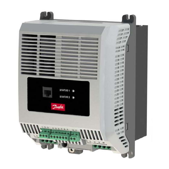
- Page 1 User Guide Danfoss CDS203 Drive Installation & Operating Instructions http://cc.danfoss.com...
- Page 2 Do not attempt to carry out any repair of the CDS 203. In the whilst power is applied to the drive or to the external case of suspected fault or malfunction, contact your local control circuits. Danfoss Compressor Sales Partner for further assistance. 2 | AB455227823946en-000101...
- Page 3 1 : Single Phase PFC 3 : Three Phase ECO Film 2.1.1. Model Variants 200 – 240V +/-10% Single Phase Input Model Code Frame Amps CDS203-22P1K5-1FH11 CDS203-22P3K0-1FH21 12.0 CDS203-22P3K0-1FH31 CDS203-22P4K0-1FH41 16.0 380 – 480V +/-10% Three Phase Input Model Code...
- Page 4 3.1. Mechanical Installation 3.1.1. General The Danfoss CDS 203 has been designed to be installed in a suitable enclosure. The drive can be through panel mounted or mounted directly onto the back of a panel using the appropriate mounting kit.
- Page 5 3. Installation 3.1.3. Drive Dimensions L1 L2 L3 A B C STATUS 1 STATUS 2 1 2 3 4 5 6 7 8 9 10 11 L1 L2 L3 226.3 8.9 215.2 8.5 201.4 7.9 165.3 6.5 144.8 5.7 177 6.96 71.7 2.82 104.4 4.11 145 Tightening Torques Weights All 400V drives with Heatsink...
- Page 6 3. Installation 3.1.5. Through panel mounting Through panel mounting is the most e cient installation in terms of both panel space and thermal management. With the heatsink protruding through the back of the electrical panel, the heat generated by the drive will be exhausted outside of the electrical panel.
- Page 7 3. Installation 3.1.7. Panel mounting the cold-plate variant The CDS 2003 is also available without a heatsink but with a coldplate that needs to be mounted onto a heat transfer surface, removing the drive losses and maintaining the coldplate temperature. Ø5.8mm L1 L2 L3 A B C...
- Page 8 3. Installation 3.2. Connection Diagram All power terminal locations are marked directly on the product with AC power input and motor connections located at the bottom of the unit. 3.2.1. Electrical Power Connections Mains (1 or 3 phase) Incoming Power Connection Additional information in section 3.2.2.
- Page 9 3. Installation 3.2.2. Incoming Power Connection Cable Selection For 1 phase supply, the mains power cables should be connected to L1/L, L2/N. F or 3 phase supplies, the mains power cables should be connected to L1, L2, and L3.
- Page 10 3. Installation 3.3. Control Wiring The CDS 203 has pluggable control terminals to support easy installation. There are three pluggable control terminal blocks split into: S erial Communications (T1-T3) I nputs (T5 – T9) O utput Relay (T10 – T11) STATUS 1 STATUS 2 1 2 3...
- Page 11 4.1.1. Access to Parameters The drive parameters can be accessed via one of the following methods: 1. ModBus Communications 2. CDS203 LCP 3. CoolSetting - Drive Setup Software 4.1.2. Operating Limits and Ramp Rates Par.
- Page 12 4. Set-up and Operation 4.1.3. Start-up Sequence Par. Modbus Description Unit Address 2-01 Start Speed 1 P1-02 2-02 Start Speed 1 Time 2-03 Start Speed 1 Acceleration Ramp Rate 0rps to Start 6000 Speed 1 2-04 Start Speed 2 P1-02 2-05 Start Speed 2 Time 2-06...
- Page 13 4. Set-up and Operation 4.1.5. Control Mode Par. Modbus Description Unit Address 1-11 Command Source 1- Terminal 0: Modbus Mode 1: Terminal Control 2: Terminal Control (AI1 Start) 3: User PID Mode 1-05 Stop Mode 0: Ramp to Stop 1: Coast to Stop 2: AC Flux Braking (IM Motor only) 3: Ramp to Minimum Speed then Coast to Stop The primary command source setting in P1-11 makes a signi cant di erence to how the drive is operated or...
- Page 14 5. Diagnostics 5.1. Trips Fault No. Description Suggested Remedy Code No Fault or No Trip No fault in trip log – no problem with the drive Instantaneous over High current from either – short-circuit on the drive output / current acceleration ramps too short / incorrect motor data.
- Page 15 5. Diagnostics Fault No. Description Suggested Remedy Code Drive output fault Check for wiring faults, loose connections or badly terminated cables between the drive and the motor Safety circuit Check the wiring of the STO circuit and any switches or devices within momentarily opened that circuit.
- Page 16 Maximum Maximum Rating Current (Type B) Cable Size Output Output Output Motor Cable Current Current Cable Size Length Non UL CDS203-22P1K5-1FH11 1.5 CDS203-22P3K0-1FH21 15.8 13.2 CDS203-22P3K0-1FH31 CDS203-22P4K0-1FH41 4.0 21.3 20.8 CDS203-22P1K5-1FC11 1.5 CDS203-22P3K0-1FC21 15.8 13.2 CDS203-22P3K0-1FC31 CDS203-22P4K0-1FC41 4.0 21.3 20.8 CDS203-24P5K5-3FH31 12.0...
Need help?
Do you have a question about the CDS203 and is the answer not in the manual?
Questions and answers