Advertisement
Quick Links
Advertisement

Summary of Contents for Bluetti EP2000
- Page 1 BLUETTI EP2000 Quick Guide V1.0...
- Page 2 Contents Overview overview EP2000 Inverter HV800 Battery Controller B700 Battery Installation Installation requirements 2. 2 Wall mounting Electrical connection Overview Connect the Ground Cables Connect the Power Cables Connect the Communication Cables Connect the AC Power Cables Connect the GRID and BACKUP Cables...
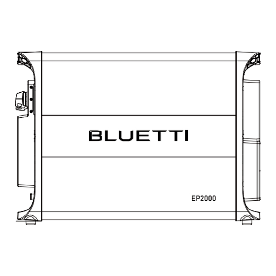
- Page 3 1. This document is for quick guidance installation only. For details, please refer to the User Manual. 2.The warranty does not cover any damage to the equipment caused by violation of the guide. 1.2 EP2000 Inverter 659,8 mm EP2000 Inverter...
- Page 4 1.3 HV800 Battery Controller 659,8 mm HV800 Battery Controller Grounding Terminal 1 Bleed Valve AC Output (To Battery) EP2000 COM Port Reserved Port BAT- Terminal Third-party Inverter COM Port Battery Signal Port SoC Indicators Grounding Terminal 2 Circuit Breaker High Voltage Power-on Indicator...
- Page 5 Fire or Flammable Material Water Max. 5° ≥1000mm ≥300mm ≥300mm Reserved Space ≥300mm ≥300mm Ground Wall drilling location 664.2mm 664.2mm 664.2mm 10-ø8,0mm EP2000 8-ø8,0mm 8-ø8,0mm 357,5mm B700 EP2000 HV800 386,5mm 357,5mm 317,5mm B700 B700 HV800 317,5mm 386,5mm 386,5mm B700 B700...
- Page 6 1000mm NOTES: 1.Please ensure that the distance from the EP2000 energy storage system to the distribution box is less than 2500mm. 2.Place the base on the ground and adjust the height of leveling feet so that the base stands stably on the ground.
- Page 7 1 EP2000 + 1 HV800 + 2 B700 1 EP2000 + 1 HV800 + 3 B700 664,2 mm 26.149 in 10-φ8,0 mm 10-φ0.315 in 664,2 mm 26.149 in 357,5 mm 357,5 mm 14.074 in 14.074 in 8-φ8,0 mm 8-φ0.315 in...
- Page 8 199 mm 199 mm 199 mm 199 mm 7.834 in 7.834 in 7.834 in 7.834 in NOTES: 1 EP2000 + 1 HV800 + 6 B700, 3 B700 on the left side, 3 B700 on the right side. JUST POWER ON...
- Page 9 3. Electrical connection 3.1 overview left side right side COM2 DRMs COM3 Earth AC G RID AC LOAD COM1 MAINTENANCE PCS1 JUST POWER ON...
- Page 10 3.2 Connect the Ground Cables left side L2=L1+3mm L4=1 mm L3=2 mm Terminal block L2 is 3 mm longer than L1. Wire Visible wire Wire even or bulge up to 1 mm right side NOTES: grounding cable (Cable conductor cross-sectional area: 10mm yellow-green cable).
- Page 11 3.3 Connect the Power Cables left side right side Click Click Click Click NOTES: The Batteries are connected in series. Take EP2000+HV800+2B700 for example. 3.4 Connect the Communication Cables left side right side JUST POWER ON...
- Page 12 3.5 Connect the AC Power Cables left side right side 3.6 Connect the GRID and BACKUP Cables 2 Nm NOTES: 1.Installation in Electrical Conduit: Maximum current 50A; Installation in Air: Maximum current 60A. 2.Please use a 5-core 10mm copper cable (5 x 10mm power cable: 5 cores, 10mm cross-section per core).
- Page 13 3.If the grid is stable, turn to “I” to use the BLUETTI EP2000 and public grid to power the loads; otherwise turn to “II” to use EP2000 Backup mode to avoid the inconvenience caused by power outage.
- Page 14 3.8 Connect PV cables PE:PV1 to Solar panel ground PV1+:To solar panel positive PV1-:To solar panel negative PE:PV2 to Solar panel ground PV2+:To solar panel positive Cable conductor PV2-:To solar panel negative cross-sectional area: PE:PV3 to Solar panel ground 2.5-4mm PV3+:To solar panel positive PV3-:To solar panel negative PE:PV4 to Solar panel ground...
- Page 15 3. 9 EMS Connection and Operations Expansion Plug 136 mm Bracket Self-tapping Fixing Screw Screw Controller Connector Function Note (Meter RS485 communication) RS485-B1 Connects to grid meter and meter RS485-B- (black) RS485-A1 Connects to grid meter and meter RS485-A+ (red) NOTES: Make sure the router is set to IEEE 802.11 b/g/n 2.4GHz.
- Page 16 3.10 Connect the METER NOTES: 1. The arrow inside the CT points to the grid. 2. Phase sequence: L1 to GRID-L1, L2 to GRID-L2, L3 to GRID-L3. 3. The CT should be tied to the L1, L2 and L3 cables of the main circuit breaker of the grid. 4.Please connect the red wire (4) to pin A, black wire (3) to pin B.
- Page 17 3.11 Typical Application Scenarios DC coupling: High power Load load AC Coupling: AC + DC Coupling: JUST POWER ON...
- Page 18 Grid and Backup electric cable recommend :10 mm (AWG 6#) In Australia, New Zealand, and South Africa, N and PE are connected together in the power distribution box. In this case, the PE of the BACKUP port of the EP2000 does not need to be connected.
- Page 19 JUST POWER ON...
- Page 20 Grid and Backup electric cable recommend :10 mm (AWG 6#) In Australia, New Zealand, and South Africa, N and PE are connected together in the power distribution box. In this case, the PE of the BACKUP port of the EP2000 does not need to be connected.
- Page 21 JUST POWER ON...
- Page 22 3.14 Other Typical Application Scenarios Backup power: Off-grid: Parallel connection on the backup side: JUST POWER ON...
- Page 23 Step 3: Wait about 40 seconds for the inverter indicator to stay steady green. Step 4: Switch on the AC circuit breakers for the inverter's GRlD block. Step 5: Turn on "System Switch" in the BLUETTl app. For details, please refer to the BLUETTI App User Manual.
- Page 26 For more information, please visit: @ BLUETTI Support DE: @Bluetti Deutschland DE: @bluetti_de UK: @Bluetti United Kingdom @ BLUETTI Official UK: @bluetti_uk Company: POWEROAK GmbH Company: POWEROAK ENERGY UK CO.,LTD Address: Lise-Meitner-Str. 14 28816 Address: Unit 2 NorthGate, Bolsover Business Park, Stuhr Germany Woodhouse Lane Chesterfield England, S44 6BD...
- Page 27 P/N:17.0307.0103-00A0...


Need help?
Do you have a question about the EP2000 and is the answer not in the manual?
Questions and answers