
Related Manuals for Baxi Bermuda Inset 2 Super


Summary of Contents for Baxi Bermuda Inset 2 Super
- Page 1 Baxi Bermuda Inset 2 Super Fireside Gas Central Heating Units Installation and Servicing Instructions W ith PDFmyURL anyone can convert entire websites to PDF!
- Page 2 W ith PDFmyURL anyone can convert entire websites to PDF!
- Page 3 Baxi Limited is one of the leading manufacturers of domestic heating products in the UK. Our first priority is to give a high quality service to our customers. Quality is built into every Baxi product - products which fulfil the demands and needs of customers, offering choice, efficiency and reliability.
- Page 4 Contents Section Page Introduction W ith PDFmyURL anyone can convert entire websites to PDF!
-
Page 5: Table Of Contents
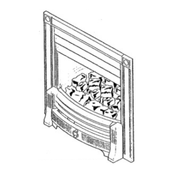
Technical Data Site Requirements Electrical Installation Arranging the Coals Checking for Spillage Annual Servicing Changing Components 10.0 Fault Finding 11.0 Flow Charts 12.0 Short Parts List 13.0 Notes Page 3 Introduction W ith PDFmyURL anyone can convert entire websites to PDF! - Page 6 Fig. 1 1.1. Description W ith PDFmyURL anyone can convert entire websites to PDF!
- Page 7 1. Your Baxi Bermuda Inset 2 Super is a central heating boiler combined with a gas fire. The firefront is of the Decorative Fuel Effect type and incorporates an optional illumination effect for use when the fire is off. The boiler will provide heating for the rest of the house and also domestic hot water if required.
-
Page 8: Technical Data
The likelihood of wall staining from convected air currents will be increased in environments where high levels of cigarette smoke or other contaminants exist. Page 4 2.0 Technical Data Bermuda Inset 2 TS Super Bermuda Inset 2 BS Super Bermuda Inset 2 FS Super Bermuda Inset 2 KS Super Bermuda Inset 2 CS Super The fire is set for Gas Type G20 at 20mbar. -
Page 9: Site Requirements
B.S. 6500 Cables. NOTE: All illustrations show the Inset 2 TS Super. The procedure for Installation, Commissioning, Servicing etc. is the same for all Bermuda Inset 2 Super models. Page 5 3.0 Site Requirements W ith PDFmyURL anyone can convert entire websites to PDF! - Page 10 W ith PDFmyURL anyone can convert entire websites to PDF!
- Page 11 Fig. 2,3,4,5 3.1 Fireplace Opening 1. The principal site requirements are determined by the boiler unit, but the following details are essential for the correct installation of the fire unit: Fireplace Opening (Fig. Height: 560mm (22in) min 590mm (23 15/64in) max Width 460mm (18in) min 560mm (22in) max...
-
Page 12: Electrical
3.2 Hearth Mounting 1. The fire unit is intended to be hearth mounted. The hearth must be of a non-combustible material at least 13mm (1/2in) thick and measuring at least 300mm (12in) deep by 600mm (23 5/8in) wide and fitted centrally about the fireplace opening. The top surface of the hearth should be a minimum of 50mm (2 in) above floor level and must be level with the base of the builders opening (Fig. - Page 13 Wiring Key b - Blue W ith PDFmyURL anyone can convert entire websites to PDF!
-
Page 14: Installation
br - Brown 4.1 Electrical Supply 1. Electricity is supplied to the fire unit via the plug and cable assembly provided with the fire. 2. The cable must be connected to the 4 pin plug and socket on the boiler. NOTE: The method of connection to the electrical supply must facilitate complete electrical isolation of the appliance. - Page 15 Fig. 20,21,21a,22,23 5.1 Initial Preparation 1. Unpack the fire unit from the carton. The coal bed and fender assemblies are packed in individual boxes within the main carton and should be left in these until required. W ith PDFmyURL anyone can convert entire websites to PDF!
- Page 16 2. Remove the instructions and other literature from the combustion box together with the contents kit and glass pack. 5.2 Electrical Connection All external wiring must be in accordance with current IEE regulations. 1. The appliance requires an electrical supply from the heating controls system. 2.
- Page 17 Re-fit the cable clamps ensuring that the outer insulation is securely held and re-fit the plug cover. Ensure that all cables are routed away from the boiler casing and hood. Page 9 W ith PDFmyURL anyone can convert entire websites to PDF!
- Page 18 Fig. 12,13,14,15,16,17 5.4 Fitting the Fire 1. Remove the fire surround trim from its poly bag (Fig. 12). The fire surround should be handled with care. 2. Position the fire surround trim around the fire combustion box and lower it into position, taking care not to trap the cable from the control panel assembly, ensure that the top lugs locate on to the top of the fire combustion box and the bottom lugs locate into the slots in the sides of the combustion (Fig.
- Page 19 9. Connect the electrical supply to the fire from the boiler (Fig. 19). Page 10 W ith PDFmyURL anyone can convert entire websites to PDF!
- Page 20 Fig. 18,19,20,20a 5.4 Fitting the Fire (continued) 7. Fit the fire gas supply pipe at the motorised valve inlet (Fig. 18). 8. Fit the fire gas supply pipe to the gas service cock on the right hand side of the boiler base ensuring gas soundness is done at both connections on the gas supply pipe (Fig.
-
Page 21: Arranging The Coals
6.0 Arranging the Coals W ith PDFmyURL anyone can convert entire websites to PDF! - Page 22 CAUTION: The coals are extremely fragile and must be handled accordingly. Gloves should be worn and any inhalation of the dust should be avoided. Keep the coals away from children at all times. Never use coals other than those originally supplied or Genuine Baxi Spare Parts. Never put additional coals on the fire.
- Page 23 5. Locate the cut-outs in the side cheeks over the profile of the underbed (Fig. 23). 6. Take the three coals with the groove in the lower faces and place them on to the location pegs on the back ridge (Fig.
- Page 24 Fig. 28,29,30 6.2 Commissioning the Fire W ith PDFmyURL anyone can convert entire websites to PDF!
- Page 25 1. Turn on the main gas and electrical supply. 2. Turn the gas service cock to the fire and boiler on position as shown, then purge any air from the fire supply pipe (Fig. 28). 3. Check for gas soundness from the gas service cock to the fire inlet connection. (BS 6891). 4.
- Page 26 W ith PDFmyURL anyone can convert entire websites to PDF!
- Page 27 Fig. 31,31a,32,33,34,35 6.3 Arranging the Coals (cont) 1. At this point it is necessary to fit the fret assembly. 2. Remove the fret from its packaging (On FS & CS models screw the finials to the fret assembly) (Fig. 31). 3.
-
Page 28: Checking For Spillage
7.0 Checking for Spillage W ith PDFmyURL anyone can convert entire websites to PDF! - Page 29 Fig. 36 & 37 7.1 Checking for Spillage CAUTION - Whilst checking for spillage care must be taken to avoid touching hot panels. 1. Before checking for spillage the worst likely operating environment for the appliance must be created. To do this, close all doors and windows in the room and operate any ceiling or extractor fans that may be present, on the wall or within other appliances.
- Page 30 5. Flue blockages. Page 15 W ith PDFmyURL anyone can convert entire websites to PDF!
- Page 31 Fig. 38,38a,38b,38c 7.4. Completion 1. Take the black painted extension piece, captive nut and screw from the fire contents kit. 2. Fit the captive nut to the rear edge of the door shield, over the hole (Fig. 38a). 3. Slide the extension piece between the door shield and the casting, ensuring the location hole locates over the pip on the door shield (Fig.
-
Page 32: Annual Servicing
Page 16 8.0 Annual Servicing W ith PDFmyURL anyone can convert entire websites to PDF! - Page 33 CAUTION: The coals are extremely fragile and must be handled accordingly. Gloves should be worn and any inhalation of the dust should be avoided. Keep the coals away from children at all times. Never use coals other than those originally supplied or Genuine Baxi Spare Parts. Never put additional coals on the fire.
- Page 34 2. Lift the controls access door away from the fender assembly (Fig. 39). 3. Turn off the gas supply at the service cock (Fig. 40). 4. Carefully remove all the coals, side cheeks, back piece and underbed (Fig. 42). 5. Remove the glass retaining assembly (Fig.
- Page 35 Fig. 45,46,47,48,49,50 8.2 Preparation (Cont) W ith PDFmyURL anyone can convert entire websites to PDF!
- Page 36 4. The thermocouple cannot be changed as an individual component. The complete assembly must be replaced in the event of one or other component failure(s). 5. Only use a Genuine Baxi Spare Part. Page 18 W ith PDFmyURL anyone can convert entire websites to PDF!
- Page 37 W ith PDFmyURL anyone can convert entire websites to PDF!
-
Page 38: Changing Components
51). 2. If necessary the coals can be cleaned with a very soft brush, and can be retouched using the black stain available direct from Baxi Heating or from your local Baxi Spares Stockist. Quote Part N° 043224 when ordering. - Page 39 W ith PDFmyURL anyone can convert entire websites to PDF!
- Page 40 CAUTION: The coals are extremely fragile and must be handled accordingly. Gloves should be worn and any inhalation of the dust should be avoided. Keep the coals away from children at all times. Never use coals other than those originally supplied or Genuine Baxi Spare Parts. Never put additional coals on the fire.
- Page 41 8. Disconnect the gas supply to the fire at the gas service cock connection (Fig. 60). Page 20 Fig. 61,62,63 W ith PDFmyURL anyone can convert entire websites to PDF!
- Page 42 9.1 Changing Components (continued) 9. Remove the two screws retaining the sides of the fire combustion box to the fire base tray (Fig. 61). 10. Remove the two screws inside the flue spigot (Fig. 62). 11. Disconnect the electrical plug from the socket (Fig.
- Page 43 Fig. 64,65 9.2 Burner and Injector 1. Undo the screw holding the burner to the controls mounting plate, and disengage the burner inlet from the injector (Fig. 64). 2. Fit the new burner in reverse order. W ith PDFmyURL anyone can convert entire websites to PDF!
- Page 44 To change the injector remove the burner as described above. 3. Using a spanner on both the adaptor barrel and fire injector, remove the injector and copper sealing washer from the barrel (Fig. 65). 4. Fit the new injector, ensuring that the copper sealing washer is in place. If the washer is damaged it must be replaced. Page 21 W ith PDFmyURL anyone can convert entire websites to PDF!
- Page 45 Fig. 66,67,68,69 9.3 Pilot/A.S.D. Assembly NOTE:The thermocouple cannot be changed as an individual component. The complete assembly must be replaced in the event of one or other component failure(s). 1. Disconnect the electrode lead from the electrode (Fig. 67) and the motorised gas valve leads from the control box (Fig.
- Page 46 5. Remove the control box heat shield retaining screw and place the shield to one side (Fig. 69). 6. Disconnect the two thermocouple interrupter leads at the control box (Fig. 69). 7. Shape the thermocouple of the replacement pilot/A.S.D. assembly in a similar manner to the original and fit in reverse order. Page 22 W ith PDFmyURL anyone can convert entire websites to PDF!
- Page 47 Fig. 70,71,72,73 9.4 Control Box W ith PDFmyURL anyone can convert entire websites to PDF!
- Page 48 1. Disconnect the earth point. 2. Remove the control box heat shield retaining screw and place the shield to one side (Fig. 71). 3. Disconnect all of the wiring connections from the control box taking note of their positions (Fig. 72).
- Page 49 Fig. 74 9.5 Motorised Gas Valve(Fig. W ith PDFmyURL anyone can convert entire websites to PDF!
- Page 50 1. Undo the thermocouple nut from the front of the motorised gas valve, and disconnect the three gas pipes from the tap body. 2. Disconnect the motorised gas valve leads from the control box (Fig. 72). 3. Undo the two screws holding the gas valve to its' bracket. Remove the valve, slackening the gas pipes at their other connections if necessary. 4.
- Page 51 Fig. 75,76,77 9.6 Control Panel 1. Disconnect the control panel connector from the front of the valve bracket (Fig. 75). 2. Lift the surround trim away from combustion box (Fig. 76). 3. Remove the cable clamp which secures the control panel cable (Fig.
- Page 52 5. Fit the new control panel taking care not to overtighten the securing nuts and reassemble in reverse order. Page 24 W ith PDFmyURL anyone can convert entire websites to PDF!
- Page 53 Fig. 78,79,80,81,82 9.7 Bulbs IMPORTANT: Only replace the bulb/s with a 12V 20W halogen capsule bulb available at most DIY outlets, specialist electrical stores or through Baxi Heating Ltd. 1. Remove the coals, placing them on a newspaper or similar to prevent soiling furnishings.
-
Page 54: Fault Finding
1. Remove the coals, placing them on a newspaper or similar to prevent soiling furnishings. 2. Lift out the glass retaining assembly (Fig. 78). 3. Carefully remove the three amber glass pieces (Fig. 80). 4. Fit the new glass and reassemble the coals. 9.9 Transformer Assembly The transformer assembly is situated at the rear of the fire at the left hand side. - Page 55 Before starting Fault Finding carry out preliminary electrical system checks i.e. Earth Continuity, Polarity, Short Circuit and Resistance to Earth. Page 26 W ith PDFmyURL anyone can convert entire websites to PDF!
-
Page 56: Flow Charts
11.0 Flow Charts Sequence of Automatic Control System W ith PDFmyURL anyone can convert entire websites to PDF! - Page 57 Page 27 In the event of a gas or electrical failure W ith PDFmyURL anyone can convert entire websites to PDF!
-
Page 58: Short Parts List
Page 28 12.0 Short parts list W ith PDFmyURL anyone can convert entire websites to PDF! - Page 59 Key No. G.C. No. Description Manufacturers Part No. Burner - Fire 244952 Pilot/ASD Assy 240096 Fire Injector F15 or 90 243038 Coal Bed Base 245640 E01-363 Coal Bed Sidecheeks and Back Pack 239278 E01-364 Coals Under-bed Pack 239279 W ith PDFmyURL anyone can convert entire websites to PDF!
-
Page 60: Notes
244712 Page 29 13.0 Notes Page 30 Page 31 Baxi Limited manufacture a comprehensive range of products for the domestic heating market Gas Central Heating Boilers (Wall, Floor and Fireside models). Independent Gas Fires. Renewal Firefronts. Gas Wall Heaters. Solid Fuel Fires. - Page 61 W ith PDFmyURL anyone can convert entire websites to PDF!
- Page 62 Page 33 W ith PDFmyURL anyone can convert entire websites to PDF!
Need help?
Do you have a question about the Bermuda Inset 2 Super and is the answer not in the manual?
Questions and answers