Advertisement
Quick Links
R-410A
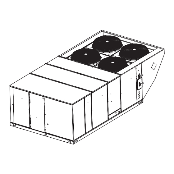
XA SERIES
15/20 Ton
60 Hertz
General . . . . . . . . . . . . . . . . . . . . . . . . . . . . . . . . . . . . . . . . . . 2
Installation . . . . . . . . . . . . . . . . . . . . . . . . . . . . . . . . . . . . . . . . 5
Limitations . . . . . . . . . . . . . . . . . . . . . . . . . . . . . . . . . . . . 5
Location. . . . . . . . . . . . . . . . . . . . . . . . . . . . . . . . . . . . . . . . 7
Rigging And Handling . . . . . . . . . . . . . . . . . . . . . . . . . . . . . 7
Ductwork . . . . . . . . . . . . . . . . . . . . . . . . . . . . . . . . . . . . . . 13
Condensate Drain . . . . . . . . . . . . . . . . . . . . . . . . . . . . . . . 13
Compressors. . . . . . . . . . . . . . . . . . . . . . . . . . . . . . . . . . . 14
Filters . . . . . . . . . . . . . . . . . . . . . . . . . . . . . . . . . . . . . . . . 14
Power And Control Wiring. . . . . . . . . . . . . . . . . . . . . . . . . 14
Optional Electric Heat . . . . . . . . . . . . . . . . . . . . . . . . . . . . 22
Options/Accessories . . . . . . . . . . . . . . . . . . . . . . . . . . . . . 22
Economizer And Power Exhaust Set Point Adjustments . 22
Optional BAS-Ready Economizer Power Exhaust Damper
Set Point Adjustment. . . . . . . . . . . . . . . . . . . . . . . . . . . . . 23
Air Balance . . . . . . . . . . . . . . . . . . . . . . . . . . . . . . . . . . . . 30
Operation . . . . . . . . . . . . . . . . . . . . . . . . . . . . . . . . . . . . . . . 32
Cooling Sequence Of Operation . . . . . . . . . . . . . . . . . . . . 32
No Outdoor Air Options . . . . . . . . . . . . . . . . . . . . . . . . . 32
1 XA-15, XA-20 Unit Limitations . . . . . . . . . . . . . . . . . . . . . .6
2 XA-15, XA-20 UNIT WEIGHTS . . . . . . . . . . . . . . . . . . . . .8
3 XA-15, XA-20 Unit Accessory Weights . . . . . . . . . . . . . . .9
4 XA-15, XA-20 Unit Clearances . . . . . . . . . . . . . . . . . . . . .12
5 Control Wire Sizes . . . . . . . . . . . . . . . . . . . . . . . . . . . . . .15
6 Electrical Data . . . . . . . . . . . . . . . . . . . . . . . . . . . . . . . . .17
7 XA-15, XA-20 Physical Data . . . . . . . . . . . . . . . . . . . . . .21
8 Electric Heat Minimum Supply Air . . . . . . . . . . . . . . . . . .22
9 Altitude/Temperature Correction Factors . . . . . . . . . . . . .26
10 Air Flow Performance - Side Duct Application . . . . . . . . .28
1 XA-20 Component Location . . . . . . . . . . . . . . . . . . . . . . 6
2 XA-20 Unit 4 Point Load Weight . . . . . . . . . . . . . . . . . . . 8
3 XA-20 Unit 6 Point Load Weight . . . . . . . . . . . . . . . . . . . 8
4 XA-15 Unit 4 Point Load Weight . . . . . . . . . . . . . . . . . . . 8
5 XA-15 Unit 6 Point Load Weight . . . . . . . . . . . . . . . . . . . 8
6 Center of Gravity . . . . . . . . . . . . . . . . . . . . . . . . . . . . . . . 8
7 XA-20 Unit Dimensions Front View . . . . . . . . . . . . . . . . . 9
8 XA-15 Unit Dimensions Front View . . . . . . . . . . . . . . . . 10
9 XA-15, XA-20 Unit Dimensions Rear View . . . . . . . . . . 11
10 XA-15, XA-20 Unit Dimensions Rain Hood . . . . . . . . . . 12
11 XA-15, XA-20 Roof Curb . . . . . . . . . . . . . . . . . . . . . . . . 12
12 Fixed Outdoor Air Damper . . . . . . . . . . . . . . . . . . . . . . 13
13 Condensate Drain . . . . . . . . . . . . . . . . . . . . . . . . . . . . . 13
TABLE OF CONTENTS
Cooling Operation Errors . . . . . . . . . . . . . . . . . . . . . . . . 33
Electric Heating Sequence Of Operations. . . . . . . . . . . . . 34
Defrost Termination . . . . . . . . . . . . . . . . . . . . . . . . . . . . 35
Interval between Defrosts. . . . . . . . . . . . . . . . . . . . . . . . 35
Forced Defrost . . . . . . . . . . . . . . . . . . . . . . . . . . . . . . . . 35
Electric Heat Operation Errors . . . . . . . . . . . . . . . . . . . . 35
Start-Up (Cooling) . . . . . . . . . . . . . . . . . . . . . . . . . . . . . . . . . 36
Charging The Unit . . . . . . . . . . . . . . . . . . . . . . . . . . . . . . . . . 37
Troubleshooting . . . . . . . . . . . . . . . . . . . . . . . . . . . . . . . . . . . 38
Unit Control Board Option Setup . . . . . . . . . . . . . . . . . . . . . . 43
Option Byte Setup . . . . . . . . . . . . . . . . . . . . . . . . . . . . . . . 43
Heat Delay Setup . . . . . . . . . . . . . . . . . . . . . . . . . . . . . . . 43
Maintenance . . . . . . . . . . . . . . . . . . . . . . . . . . . . . . . . . . . . . 43
Normal Maintenance . . . . . . . . . . . . . . . . . . . . . . . . . . . . . 43
Filters . . . . . . . . . . . . . . . . . . . . . . . . . . . . . . . . . . . . . . . . 43
Motors . . . . . . . . . . . . . . . . . . . . . . . . . . . . . . . . . . . . . . . . 43
Blower Shaft Bearing . . . . . . . . . . . . . . . . . . . . . . . . . . . . 44
Outdoor Coil . . . . . . . . . . . . . . . . . . . . . . . . . . . . . . . . . . . 44
LIST OF TABLES
11 Air Flow Performance - Bottom Duct Application . . . . . . .29
12 RPM Selection . . . . . . . . . . . . . . . . . . . . . . . . . . . . . . . . .30
13 Indoor Blower Specifications . . . . . . . . . . . . . . . . . . . . . .30
14 Power Exhaust Specifications . . . . . . . . . . . . . . . . . . . . .30
15 Additional Static Resistance . . . . . . . . . . . . . . . . . . . . . . .31
16 Limit Control Setting . . . . . . . . . . . . . . . . . . . . . . . . . . . . .35
17 Electric Heat Anticipator Setpoint . . . . . . . . . . . . . . . . . . .36
18 Unit Control Board Flash Codes . . . . . . . . . . . . . . . . . . . .42
19 Heat Delay . . . . . . . . . . . . . . . . . . . . . . . . . . . . . . . . . . . .43
LIST OF FIGURES
14 Field Wiring Disconnect - Heat Pump Unit With/Without
Electric Heat . . . . . . . . . . . . . . . . . . . . . . . . . . . . . . . . . 15
15 Typical Field Wiring 24 Volt Thermostat . . . . . . . . . . . . 16
16 Enthalpy Set Point Chart . . . . . . . . . . . . . . . . . . . . . . . . 24
17 Honeywell Economizer Control W7212 . . . . . . . . . . . . . 24
18 Belt Adjustment . . . . . . . . . . . . . . . . . . . . . . . . . . . . . . . 25
19 Altitude/Temperature Correction Factors . . . . . . . . . . . 26
20 Pressure Drop Across A Dry Indoor Coil Vs. Supply Air CFM
For All Unit Tonnages . . . . . . . . . . . . . . . . . . . . . . . . . . 30
21 XA-15 (15 Ton) Charging Chart . . . . . . . . . . . . . . . . . . 37
22 XA-20 (20 Ton) Charging Chart . . . . . . . . . . . . . . . . . . 37
23 Unit Control Board . . . . . . . . . . . . . . . . . . . . . . . . . . . . . 42
638596-BIM-D-0213
Advertisement

Related Manuals for Johnson Controls XA-15


Summary of Contents for Johnson Controls XA-15
- Page 1 21 XA-15 (15 Ton) Charging Chart ....37 11 XA-15, XA-20 Roof Curb ......12 22 XA-20 (20 Ton) Charging Chart .
- Page 2 This product must be installed in strict compliance with building, electrical, and mechanical codes. the enclosed installation instructions and any applicable local, state and national codes including, but not limited to, building, electrical, and mechanical codes. Johnson Controls Unitary Products...
- Page 3 For outdoor installation only. For installation on combustible material.. Additional information is available in the following reference forms: • Technical Guide - XA-15/XA-20, 652299 • General Installation - XA-15/XA-20, 638596 Improper installation may create a condition where the Renewal Parts...
- Page 4 Y = Options 4 & 5 Z = Options 3, 4 & 5 Options 1 = Disconnect 2 = Non-Pwr'd Conv. Outlet 3 = Smoke Detector S.A. 4 = Smoke Detector R.A. 5 = Pwr'd Conv. Outlet Johnson Controls Unitary Products...
- Page 5 AE-011-07 or call the applications department for In U.S.A.: Unitary Products @ 1-877-UPG-SERV for guidance. National Electrical Code, ANSI/NFPA No. 70 - Latest Additional accessories may be needed for stable Edition operation at temperatures below 30°F. Johnson Controls Unitary Products...
- Page 6 1” NPT Evaporator Valve 14 Gauge Condensate Drain Coils Base Rails with Lifting Holes Figure 1: XA-20 Component Location Table 1: XA-15, XA-20 Unit Limitations Unit Limitations Size Unit Voltage Applied Voltage Outdoor DB Temp (Tons) Max (°F) 208/230-3-60 460-3-60...
- Page 7 All panels must be secured in place when the unit is service. Refer to Table 4 for clearances required for lifted. combustible construction, servicing, and proper unit operation. The condenser coils should be protected from rigging cable damage with plywood or other suitable material. Johnson Controls Unitary Products...
- Page 8 638596-BIM-D-0213 Figure 2: XA-20 Unit 4 Point Load Weight Figure 3: XA-20 Unit 6 Point Load Weight Figure 4: XA-15 Unit 4 Point Load Weight Figure 5: XA-15 Unit 6 Point Load Weight FRONT FRONT FRONT LEFT Figure 6: Center of Gravity Table 2: XA-15, XA-20 UNIT WEIGHTS Weight (lbs.)
- Page 9 638596-BIM-D-0213 Table 3: XA-15, XA-20 Unit Accessory Weights Weight (lbs.) Unit Accessory Shipping Operating Economizer Power Exhaust Electric Heat Double Wall Motorized Damper Barometric Damper Econ./Motorized Damper Rain Hood Econ./Power Exhaust Rain Hood Wood Skid Roof Curb 1. Weight given is for the maximum heater size available (72KW).
- Page 10 For curb mounted units, refer to the curb hanger 9-1/4" dimensions of the curb for the proper size of the 12-1/2" 9-3/4" supply and return air duct connections. Figure 8: XA-15 Unit Dimensions Front View Utilities Entry Opening Size Hole Used For Diameter 1-1/8”...
- Page 11 39-5/8" REAR ACCESS Duct Flange Kit. VIEW Figure 9: XA-15, XA-20 Unit Dimensions Rear View NOTE: Units are shipped with the bottom duct openings covered. An accessory flange kit is available for connecting side ducts. For bottom duct applications: For side duct applications:...
- Page 12 5” 28-3/16” 92” Rear View LH View Detail “Y” Unit with Rain Hoods Figure 10: XA-15, XA-20 Unit Dimensions Rain Hood Table 4: XA-15, XA-20 Unit Clearances Direction Distance (in.) Direction Distance (in.) 72 With 36 Maximum Horizontal Overhang Right...
- Page 13 Figure 13: Condensate Drain possible. Cut an opening 16 inches high by 18 inches wide in the ductwork to accommodate the damper. Using the holes in the Johnson Controls Unitary Products...
- Page 14 Two-inch filters are supplied with each unit. For XA-20 models, properly fused. the filter rack can be easily modified to accommodate four inch filters. Filters must always be installed ahead of the evaporator Johnson Controls Unitary Products...
- Page 15 Refer to Table 5: Control Wire Sizes Table 5 for control wire sizing and maximum length. Wire Size Maximum Length 18 AWG 150 Feet 1. From the unit to the thermostat and back to the unit. Johnson Controls Unitary Products...
- Page 16 X is an input to the thermostat to display Error Status conditions. Figure 15: Typical Field Wiring 24 Volt Thermostat 208/230-3-60 unit control transformers are factory wired for 230v power supply. Change tap on transformer for 208-3-60 operation. See unit wiring diagram. Johnson Controls Unitary Products...
- Page 17 638596-BIM-D-0213 Table 6: Electrical Data XA-15, XA-20 - Standard Drive Without Powered Convenience Outlet OD Fan Supply Max Fuse Compressors Motors Blower Conv Electric Heat Option Size Breaker (each) Volt (each) Motor Outlet (Tons) (Amps) Size (Amps) RLA LRA MCC...
- Page 18 638596-BIM-D-0213 XA-15, XA-20 - Standard Drive With Powered Convenience Outlet OD Fan Supply Max Fuse Compressors Motors Blower Conv Electric Heat Option Size Breaker (each) Volt (each) Motor Outlet (Tons) (Amps) Size (Amps) RLA LRA MCC Model Stages Amps None 92.9...
- Page 19 638596-BIM-D-0213 XA-15, XA-20 - High Static Drive Without Powered Convenience Outlet OD Fan Supply Max Fuse Compressors Motors Blower Conv Electric Heat Option Size Breaker (each) Volt (each) Motor Outlet (Tons) (Amps) Size (Amps) RLA LRA MCC Model Stages Amps None 87.5...
- Page 20 638596-BIM-D-0213 XA-15, XA-20 - High Static Drive With Powered Convenience Outlet OD Fan Supply Max Fuse Compressors Motors Blower Conv Electric Heat Option Size Breaker (each) Volt (each) Motor Outlet (Tons) (Amps) Size (Amps) RLA LRA MCC Model Stages Amps None 97.5...
- Page 21 638596-BIM-D-0213 Table 7: XA-15, XA-20 Physical Data Models Component XA-15 XA-20 Nominal Tonnage AHRI COOLING PERFORMANCE 188,700 261,400 Gross Capacity @ AHRI A point (Btu/hr) 180,000 250,000 AHRI net capacity (Btu/hr) 10.6 10.5 11.9 10.9 IEER 6000 8000 Nominal CFM 17.0...
- Page 22 Ventilation Set Point) setting and there is a call for free cooling, the actuator modulates from the minimum position to the full open position based on the highest call from either the mixed air sensor input or the AQ voltage input. Johnson Controls Unitary Products...
- Page 23 Remove the economizer access panel from the unit. Loosen, exhaust is needed. The adjustment screw can be set between but do not remove the two panel latches. Locate the 25 to 85 degrees open. Replace the economizer access panel. Johnson Controls Unitary Products...
- Page 24 Damper Min. Position Screw Indoor Air Quality Max. Adjustment Screw Indoor Air Quality Indoor Air Quality Min. Adjustment Screw Free Cool Free Cooling LED Economizer Enthalpy Set Point Adjustment Screw Figure 17: Honeywell Economizer Control W7212 Johnson Controls Unitary Products...
- Page 25 Air density correction factors are shown in Table 9 and Figure 19. *Never Loosen (C)* Figure 18: Belt Adjustment Johnson Controls Unitary Products...
- Page 26 This value must be corrected for elevation. Example 2: A system, located at 5,000 feet of elevation, is to deliver 6,000 CFM at a static pressure of 1.5". Use the unit BHP at 5,000 ft. = 3.2 x .832 = 2.66 Johnson Controls Unitary Products...
- Page 27 Size Motor Blower 6 Turns 5 Turns 4 Turns 3 Turns 2 Turns 1 Turn Fully Model (Tons) Sheave Sheave Open Open Open Open Open Open Closed 5.75 1VP60 BK110 8.63 1VP60 BK090 1035 1075 1120 Johnson Controls Unitary Products...
- Page 28 638596-BIM-D-0213 Table 10: Air Flow Performance - Side Duct Application XA-15 (15 Ton) Side Duct Available External Static Pressure - IWG Air Flow (CFM) RPM BHP RPM BHP RPM BHP RPM BHP RPM BHP RPM BHP RPM BHP RPM BHP RPM BHP RPM BHP RPM BHP RPM BHP Standard 5 HP &...
- Page 29 638596-BIM-D-0213 Table 11: Air Flow Performance - Bottom Duct Application XA-15 (15 Ton) Bottom Duct Available External Static Pressure - IWG Air Flow (CFM) RPM BHP RPM BHP RPM BHP RPM BHP RPM BHP RPM BHP RPM BHP RPM BHP RPM BHP RPM BHP RPM BHP RPM BHP Standard 5 HP &...
- Page 30 Failure to properly adjust the total system air quantity can result in extensive blower damage. After readings have been obtained, remove the tubes and reinstall the two 5/16” dot plugs that were removed in Step 1. Johnson Controls Unitary Products...
- Page 31 638596-BIM-D-0213 NOTE: De-energize the compressors before taking any test For the XA-15 Model, high speed drive accessory 1LD0413 (containing a smaller blower pulley and a shorter belt) is measurements to assure a dry indoor coil. available for applications requiring the supply air blower to Supply Air Drive Adjustment produce higher CFM's and/or higher static pressures.
- Page 32 Economizer With Dual Enthalpy Sensors and #4 are energized, provided they have not been locked-out.) The operation with the dual enthalpy sensors is identical to the single sensor except that a second enthalpy sensor is mounted Johnson Controls Unitary Products...
- Page 33 The low-pressure limit switch is not monitored during the initial 30 seconds of a cooling system's operation. For the following has closed, the unit will resume operation. 30 seconds, the UCB will monitor the low-pressure switch to Johnson Controls Unitary Products...
- Page 34 ASCD timer is satisfied, the DC closes its internal unnecessary defrost cycles caused by refrigeration surges such compressor relay contacts, sending a 24vac signal to the MV1 as those that occur at the start of a heating cycle. Johnson Controls Unitary Products...
- Page 35 “ON” cycles the limit is monitored at all times. and may result in the lowering of the temperature within the conditioned space. Refer to Table 17 for the required electric heat anticipator setting. Johnson Controls Unitary Products...
- Page 36 Check indoor blower rotation. Set the thermostat to the lowest temperature setting. • If blower rotation is in the wrong direction. Refer to Phasing Section in general information section. Turn “OFF” all electric power to unit. Johnson Controls Unitary Products...
- Page 37 2. This chart is applicable to unit with the TXV's left to the factory setting. If the TXV's have been adjusted in the field, the charging chart may no longer apply. Figure 21: XA-15 (15 Ton) Charging Chart 20-Ton Charging Chart Cooling mode Outdoor Temp (ºF)
- Page 38 Proper wiring between the room thermostat and the out the compressor for repeat trips. The UCB should be UCB, and flashing an alarm code. If not, press and release the c. Loose wiring from the room thermostat to the UCB Johnson Controls Unitary Products...
- Page 39 15. If none of the above corrected the error, test the integrity of five alarms on the LED. If the compressor is locked out, the UCB. Disconnect the C1 terminal wire and jumper it to remove any call for cooling at the thermostat or by Johnson Controls Unitary Products...
- Page 40 C1 and the compressor contactor. the 24 volts to the Y1 “ECON” terminal even though the economizer is not providing free cooling. To test the Johnson Controls Unitary Products...
- Page 41 Unit Control Board Flash Codes Flash codes that do and do not represent alarms are listed in Table 18. Various flash codes are utilized by the unit control board (UCB) to aid in troubleshooting. Flash codes are distinguished by the Johnson Controls Unitary Products...
- Page 42 EEPROM Storage Failure No Power or Control Failure 1. Non-alarm condition. Check Alarm History Reset All ASCDs For One Cycle Non Alarm Condition Green LED Flashing Current Alarm Flashed Red LED Figure 23: Unit Control Board Johnson Controls Unitary Products...
- Page 43 60 seconds, the display will revert to its normal display, exiting the Option Setup mode. When saving, the control board only saves the parameters for the currently displayed mode (Option Byte or Heat Delay). Damage can occur if the bearings are overlubricated. Use grease sparingly. Johnson Controls Unitary Products...
- Page 44 Do not over lubricate. Run the motor for ten Subject to change without notice. Printed in U.S.A. 638596-BIM-D-0213 Copyright © 2013 by Johnson Controls, Inc. All rights reserved. Supersedes: 638596-BIM-C-0112 Johnson Controls Unitary Products 5005 York Drive...
Need help?
Do you have a question about the XA-15 and is the answer not in the manual?
Questions and answers