Table of Contents
Advertisement
Quick Links
R-410A
XA SERIES W/SMART EQUIPMENT™
15/20 Ton
60 Hertz
General . . . . . . . . . . . . . . . . . . . . . . . . . . . . . . . . . . . . . . . . . . 2
Installation . . . . . . . . . . . . . . . . . . . . . . . . . . . . . . . . . . . . . . . . 5
Limitations . . . . . . . . . . . . . . . . . . . . . . . . . . . . . . . . . . . . 5
Location. . . . . . . . . . . . . . . . . . . . . . . . . . . . . . . . . . . . . . . . 7
Rigging And Handling . . . . . . . . . . . . . . . . . . . . . . . . . . . . . 7
Ductwork . . . . . . . . . . . . . . . . . . . . . . . . . . . . . . . . . . . . . . 13
Condensate Drain . . . . . . . . . . . . . . . . . . . . . . . . . . . . . . . 13
Compressors. . . . . . . . . . . . . . . . . . . . . . . . . . . . . . . . . . . 14
Filters . . . . . . . . . . . . . . . . . . . . . . . . . . . . . . . . . . . . . . . . 14
Power And Control Wiring. . . . . . . . . . . . . . . . . . . . . . . . . 14
Field Installed Electric Heat Accessories . . . . . . . . . . . . . 23
Options/Accessories . . . . . . . . . . . . . . . . . . . . . . . . . . . . . 23
Economizer Sequences . . . . . . . . . . . . . . . . . . . . . . . . . . 23
Dry Bulb Changeover . . . . . . . . . . . . . . . . . . . . . . . . . . . . 23
Single Enthalpy Changeover. . . . . . . . . . . . . . . . . . . . . . . 23
Dual Enthalpy Changeover . . . . . . . . . . . . . . . . . . . . . . . . 23
Auto. . . . . . . . . . . . . . . . . . . . . . . . . . . . . . . . . . . . . . . . . . 23
Free Cooling Operation. . . . . . . . . . . . . . . . . . . . . . . . . . . 23
Power Exhaust . . . . . . . . . . . . . . . . . . . . . . . . . . . . . . . . . 24
Setpoints . . . . . . . . . . . . . . . . . . . . . . . . . . . . . . . . . . . . . . 24
Inputs . . . . . . . . . . . . . . . . . . . . . . . . . . . . . . . . . . . . . . . . 24
Outputs . . . . . . . . . . . . . . . . . . . . . . . . . . . . . . . . . . . . . . . 24
1 XAT15, XAT20 Unit Limitations . . . . . . . . . . . . . . . . . . . . 6
2 XAT15, XAT20 Unit Weight . . . . . . . . . . . . . . . . . . . . . . . 8
3 XAT15, XAT20 Unit Accessory Weights . . . . . . . . . . . . . . 9
4 XAT15, XAT20 Unit Clearances . . . . . . . . . . . . . . . . . . . 12
5 Control Wire Sizes . . . . . . . . . . . . . . . . . . . . . . . . . . . . . 15
6 Electrical Data . . . . . . . . . . . . . . . . . . . . . . . . . . . . . . . . . 17
7 XAT15, XAT20 Physical Data . . . . . . . . . . . . . . . . . . . . . 21
8 Electric Heat Minimum Supply Air . . . . . . . . . . . . . . . . . . 23
9 Smart Equipment™ Economizer Board Details . . . . . . . 25
10 Altitude/Temperature Correction Factors . . . . . . . . . . . . 30
1 XAT20 Component Location . . . . . . . . . . . . . . . . . . . . . . 6
2 XAT20 Unit 4 Point Load Weight . . . . . . . . . . . . . . . . . . . 8
3 XAT20 Unit 6 Point Load Weight . . . . . . . . . . . . . . . . . . . 8
4 XAT15 Unit 4 Point Load Weight . . . . . . . . . . . . . . . . . . . 8
5 XAT15 Unit 6 Point Load Weight . . . . . . . . . . . . . . . . . . . 8
6 Center of Gravity . . . . . . . . . . . . . . . . . . . . . . . . . . . . . . . 8
7 XAT20 Unit Dimensions Front View . . . . . . . . . . . . . . . . . 9
8 XAT15 Unit Dimensions Front View . . . . . . . . . . . . . . . . 10
9 XAT15, XAT20 Unit Dimensions Rear View . . . . . . . . . 11
10 XAT15, XAT20 Unit Dimensions Rain Hood . . . . . . . . . 12
11 XAT15, XAT20 Roof Curb . . . . . . . . . . . . . . . . . . . . . . . 12
12 Fixed Outdoor Air Damper . . . . . . . . . . . . . . . . . . . . . . . 13
TABLE OF CONTENTS
Operation . . . . . . . . . . . . . . . . . . . . . . . . . . . . . . . . . . . . . 24
Set Point Adjustment. . . . . . . . . . . . . . . . . . . . . . . . . . . . . 28
Air Balance . . . . . . . . . . . . . . . . . . . . . . . . . . . . . . . . . . . . 34
Sequence Of Operation . . . . . . . . . . . . . . . . . . . . . . . . . . . . 36
Cooling Sequence Of Operation . . . . . . . . . . . . . . . . . . . . 36
Cooling Operation Errors . . . . . . . . . . . . . . . . . . . . . . . . 36
Electric Heating Sequence Of Operations . . . . . . . . . . . . 37
Defrost Termination . . . . . . . . . . . . . . . . . . . . . . . . . . . . 38
Interval between Defrosts . . . . . . . . . . . . . . . . . . . . . . . 38
Forced Defrost . . . . . . . . . . . . . . . . . . . . . . . . . . . . . . . . 38
Electric Heat Operation Errors . . . . . . . . . . . . . . . . . . . . 38
Start-Up (Cooling) . . . . . . . . . . . . . . . . . . . . . . . . . . . . . . . . . 39
Charging The Unit . . . . . . . . . . . . . . . . . . . . . . . . . . . . . . . . . 40
Maintenance . . . . . . . . . . . . . . . . . . . . . . . . . . . . . . . . . . . . . 41
Normal Maintenance . . . . . . . . . . . . . . . . . . . . . . . . . . . . . 41
Filters . . . . . . . . . . . . . . . . . . . . . . . . . . . . . . . . . . . . . . . . 41
Motors . . . . . . . . . . . . . . . . . . . . . . . . . . . . . . . . . . . . . . . . 41
Blower Shaft Bearing . . . . . . . . . . . . . . . . . . . . . . . . . . . . 41
Outdoor Coil . . . . . . . . . . . . . . . . . . . . . . . . . . . . . . . . . . . 41
Start-Up Sheet . . . . . . . . . . . . . . . . . . . . . . . . . . . . . . . . . . . 48
LIST OF TABLES
11 Air Flow Performance - Side Duct Application . . . . . . . . 32
12 Air Flow Performance - Bottom Duct Application . . . . . . 33
13 RPM Selection . . . . . . . . . . . . . . . . . . . . . . . . . . . . . . . . 34
14 Indoor Blower Specifications . . . . . . . . . . . . . . . . . . . . . 34
15 Power Exhaust Specifications . . . . . . . . . . . . . . . . . . . . 34
16 Additional Static Resistance . . . . . . . . . . . . . . . . . . . . . . 35
17 Limit Control Setting . . . . . . . . . . . . . . . . . . . . . . . . . . . . 38
18 Electric Heat Anticipator Setpoint . . . . . . . . . . . . . . . . . . 39
19 Smart Equipment™ UCB Details . . . . . . . . . . . . . . . . . . 42
20 Cable for FC Buses and SA Buses in Order of Preference . 47
LIST OF FIGURES
13 Condensate Drain . . . . . . . . . . . . . . . . . . . . . . . . . . . . . 13
Electric Heat. . . . . . . . . . . . . . . . . . . . . . . . . . . . . . . . . . 15
15 Typical Field Wiring 24 Volt Thermostat . . . . . . . . . . . . 16
16 SE-ECO1001-0 Economizer Controller . . . . . . . . . . . . . 25
17 Belt Adjustment . . . . . . . . . . . . . . . . . . . . . . . . . . . . . . . 29
18 Altitude/Temperature Correction Factors . . . . . . . . . . . . 30
For All Unit Tonnages . . . . . . . . . . . . . . . . . . . . . . . . . . 34
20 XAT15 (15 Ton) Charging Chart . . . . . . . . . . . . . . . . . . 40
21 XAT20 (20 Ton) Charging Chart . . . . . . . . . . . . . . . . . . 40
22 Unit Control Board . . . . . . . . . . . . . . . . . . . . . . . . . . . . . 42
5180778-TIM-G-0119
Advertisement
Table of Contents

Related Manuals for Johnson Controls XAT15


Summary of Contents for Johnson Controls XAT15
-
Page 1: Table Of Contents
11 Air Flow Performance - Side Duct Application ..32 2 XAT15, XAT20 Unit Weight ..... . . 8 12 Air Flow Performance - Bottom Duct Application . -
Page 2: General
This product must be installed in strict compliance with building, electrical, and mechanical codes. the enclosed installation instructions and any applicable local, state and national codes including, but not limited to, building, electrical, and mechanical codes. Johnson Controls Ducted Systems... - Page 3 For installation on combustible material. Additional information is available in the following reference forms: • Technical Guide - XAT15/XAT20, 5123287 • General Installation - XAT15/XAT20, 5180778 • Electric Heat Accessory Installation - 5128261 Improper installation may create a condition where the •...
- Page 4 Y = Options 4 & 5 Z = Options 3, 4 & 5 Options 1 = Disconnect 2 = Non-Pwr'd Conv. Outlet 3 = Smoke Detector S.A. 4 = Smoke Detector R.A. 5 = Pwr'd Conv. Outlet Johnson Controls Ducted Systems...
-
Page 5: Installation
Ducted Systems @ 1-877-874-SERV for In U.S.A.: guidance. Additional accessories may be needed for National Electrical Code, ANSI/NFPA No. 70 - Latest stable operation at temperatures below 30°F. Edition Johnson Controls Ducted Systems... -
Page 6: Xat15, Xat20 Unit Limitations
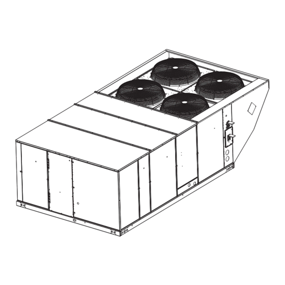
1” NPT Evaporator Valve 14 Gauge Condensate Drain Coils Base Rails with Lifting Holes Figure 1: XAT20 Component Location Table 1: XAT15, XAT20 Unit Limitations Unit Limitations Size Unit Voltage SCCR (kVA) Applied Voltage Outdoor DB Temp (Tons) Max (°F) -
Page 7: Location
All panels must be secured in place when the unit is lifted. The condenser coils should be protected from rigging cable damage with plywood or other suitable material. Johnson Controls Ducted Systems... -
Page 8: Xat15, Xat20 Unit Weight
5180778-TIM-G-0119 Figure 2: XAT20 Unit 4 Point Load Weight Figure 3: XAT20 Unit 6 Point Load Weight Figure 4: XAT15 Unit 4 Point Load Weight Figure 5: XAT15 Unit 6 Point Load Weight FRONT FRONT FRONT LEFT Figure 6: Center of Gravity Table 2: XAT15, XAT20 Unit Weight Weight (lbs.) -
Page 9: Xat15, Xat20 Unit Accessory Weights
5180778-TIM-G-0119 Table 3: XAT15, XAT20 Unit Accessory Weights Weight (lbs.) Unit Accessory Shipping Operating Economizer Power Exhaust Electric Heat Double Wall Motorized Damper Barometric Damper Econ./Motorized Damper Rain Hood Econ./Power Exhaust Rain Hood Wood Skid Roof Curb 1. Weight given is for the maximum heater size available (72KW). -
Page 10: Xat15 Unit Dimensions Front View
For curb mounted units, refer to the curb hanger 9-1/4" dimensions of the curb for the proper size of the 12-1/2" 9-3/4" supply and return air duct connections. Figure 8: XAT15 Unit Dimensions Front View Utilities Entry Opening Size Hole Used For Diameter 1-1/8”... -
Page 11: Xat15, Xat20 Unit Dimensions Rear View
39-5/8" REAR ACCESS Duct Flange Kit. VIEW Figure 9: XAT15, XAT20 Unit Dimensions Rear View NOTE: Units are shipped with the bottom duct openings covered. An accessory flange kit is available for connecting side ducts. For bottom duct applications: For side duct applications:... -
Page 12: Xat15, Xat20 Unit Clearances
5” 28-3/16” 92” Rear View LH View Detail “Y” Unit with Rain Hoods Figure 10: XAT15, XAT20 Unit Dimensions Rain Hood Table 4: XAT15, XAT20 Unit Clearances Direction Distance (in.) Direction Distance (in.) 72 With 36 Maximum Horizontal Overhang Right... -
Page 13: Ductwork
Figure 13: Condensate Drain possible. Cut an opening 16 inches high by 18 inches wide in the ductwork to accommodate the damper. Using the holes in the Johnson Controls Ducted Systems... -
Page 14: Compressors
Two-inch filters are supplied with each unit. For XAT20 models, properly fused. the filter rack can be easily modified to accommodate four inch filters. Filters must always be installed ahead of the evaporator Johnson Controls Ducted Systems... -
Page 15: Control Wire Sizes
Refer to Table 5 for control wire sizing and maximum length. Table 5: Control Wire Sizes Wire Size Maximum Length 18 AWG 150 Feet 1. From the unit to the thermostat and back to the unit. Johnson Controls Ducted Systems... -
Page 16: Typical Field Wiring 24 Volt Thermostat
X is an input to the thermostat to display Error Status condi ons. Figure 15: Typical Field Wiring 24 Volt Thermostat 208/230-3-60 unit control transformers are factory wired for 230v power supply. Change tap on transformer for 208-3-60 operation. See unit wiring diagram. Johnson Controls Ducted Systems... -
Page 17: Electrical Data
5180778-TIM-G-0119 Table 6: Electrical Data XAT15, XAT20 - Standard Drive Without Powered Convenience Outlet OD Fan Supply Max Fuse Compressors Electric Heat Motors Blower Conv Size Breaker (each) (Field Installed Accessory Only) Volt (each) Motor Outlet (Tons) (Amps) Size (Amps) - Page 18 5180778-TIM-G-0119 XAT15, XAT20 - Standard Drive With Powered Convenience Outlet OD Fan Supply Max Fuse Compressors Electric Heat Motors Blower Conv Size Breaker (each) (Field Installed Accessory Only) Volt (each) Motor Outlet (Tons) (Amps) Size (Amps) RLA LRA MCC Model...
- Page 19 5180778-TIM-G-0119 XAT15, XAT20 - High Static Drive Without Powered Convenience Outlet OD Fan Supply Max Fuse Compressors Electric Heat Motors Blower Conv Size Breaker (each) (Field Installed Accessory Only) Volt (each) Motor Outlet (Tons) (Amps) Size (Amps) RLA LRA MCC...
- Page 20 5180778-TIM-G-0119 XAT15, XAT20 - High Static Drive With Powered Convenience Outlet OD Fan Supply Max Fuse Compressors Electric Heat Motors Blower Conv Size Breaker (each) (Field Installed Accessory Only) Volt (each) Motor Outlet (Tons) (Amps) Size (Amps) RLA LRA MCC...
-
Page 21: Xat15, Xat20 Physical Data
5180778-TIM-G-0119 Table 7: XAT15, XAT20 Physical Data Models Component XAT15 XAT20 Nominal Tonnage AHRI COOLING PERFORMANCE Gross Capacity @ AHRI A point (Btu/hr) 181,600 261,400 AHRI net capacity (Btu/hr) 176,000 240,000 10.6 IEER with Constant Volume 11.8 IEER with Intellispeed 13.2... - Page 22 5180778-TIM-G-0119 Table 7: XAT15, XAT20 Physical Data (Continued) Models Component XAT15 XAT20 Nominal Tonnage Motor Sheave 1VP60 1VP60 1VP60 1VP60 Blower Sheave BK120 BK100 BK110 BK090 Belt BX81 BX78 BX78 BX75 Motor HP each 1750 1750 1750 1760 Frame size...
-
Page 23: Field Installed Electric Heat Accessories
The position of When the control determines that the outside air is suitable, the the damper is set proportionally between the "Economizer first stage of cooling will always be free cooling. Johnson Controls Ducted Systems... -
Page 24: Power Exhaust
Economizer Damper Position For Exhaust Fan On. is less than Economizer Setpoint -1°F, the control starts a 12- minute timer to de-energize a compressor output. c. De-energizes exhaust fan when economizer output is below the Economizer Damper Position for Exhaust Fan Johnson Controls Ducted Systems... -
Page 25: Smart Equipment™ Economizer Board Details
Negative of the SA BUS communication Common for SA BUS power and circuit to the UCB. Through the unit wiring harness, may continue communication circuits on to the 4-stage board and/or fault detection & diagnostics board Johnson Controls Ducted Systems... - Page 26 24V~ IN Pin connections at right on upper edge of economizer board 24 VAC common connection to power the economizer board. 24 VAC transformer Common referenced to Connects through circuit traces to C/COM terminals and pins cabinet ground distributed on the economizer board. Johnson Controls Ducted Systems...
- Page 27 24 VAC common/0-10 VDC negative for the air Connects through circuit trace to 24V~ IN pin COM monitoring station sensor 24 VAC hot supplied for the building pressure 24V~ Connects through circuit trace to 24V~ IN pin HOT sensor Johnson Controls Ducted Systems...
-
Page 28: Optional Bas-Ready Economizer Power Exhaust Damper Set Point Adjustment
IAQ voltage input. drawing low amperage, has similar suction and discharge • Optional CO2 Space Sensor Kit Part #2AQ04700524 pressures, or producing a high noise level, the scroll is misphased.) • Optional CO2 Sensor Kit Part #2AQ04700624 Johnson Controls Ducted Systems... -
Page 29: Belt Adjustment
Check the belt tension at least two times during the first 24 hours of operation. Any retensioning should fall between the min. and max. deflection force values. 5. After adjusting re-tighten nuts (A). Johnson Controls Ducted Systems... -
Page 30: Altitude/Temperature Correction Factors
This value must be corrected for elevation. Example 2: A system, located at 5,000 feet of elevation, is to deliver 6,000 CFM at a static pressure of 1.5". Use the unit BHP at 5,000 ft. = 3.2 x .832 = 2.66 Johnson Controls Ducted Systems... - Page 31 Size Motor Blower 6 Turns 5 Turns 4 Turns 3 Turns 2 Turns 1 Turn Fully Model (Tons) Sheave Sheave Open Open Open Open Open Open Closed 5.75 1VP60 BK110 8.63 1VP60 BK090 1035 1075 1120 Johnson Controls Ducted Systems...
-
Page 32: Air Flow Performance - Side Duct Application
5180778-TIM-G-0119 Table 11: Air Flow Performance - Side Duct Application XAT15 (15 Ton) Side Duct Available External Static Pressure - IWG Air Flow (CFM) RPM BHP RPM BHP RPM BHP RPM BHP RPM BHP RPM BHP RPM BHP RPM BHP RPM BHP RPM BHP RPM BHP RPM BHP Standard 5 HP &... -
Page 33: Air Flow Performance - Bottom Duct Application
5180778-TIM-G-0119 Table 12: Air Flow Performance - Bottom Duct Application XAT15 (15 Ton) Bottom Duct Available External Static Pressure - IWG Air Flow (CFM) RPM BHP RPM BHP RPM BHP RPM BHP RPM BHP RPM BHP RPM BHP RPM BHP RPM BHP RPM BHP RPM BHP RPM BHP Standard 5 HP &... -
Page 34: Air Balance
Failure to properly adjust the total system air quantity can result in extensive blower damage. After readings have been obtained, remove the tubes and reinstall the two 5/16” dot plugs that were removed in Step 1. Johnson Controls Ducted Systems... -
Page 35: Additional Static Resistance
5180778-TIM-G-0119 NOTE: De-energize the compressors before taking any test For the XAT15 Model, high speed drive accessory 1LD0413 measurements to assure a dry indoor coil. (containing a smaller blower pulley and a shorter belt) is available for applications requiring the supply air blower to produce higher CFM's and/or higher static pressures. -
Page 36: Sequence Of Operation
UCB will lock-out the associated compressor. When energized, the indoor blower has a minimum run time of If the other compressor is inactive, the condenser fans will be 30 seconds. de-energized. Johnson Controls Ducted Systems... -
Page 37: Electric Heating Sequence Of Operations
“R” and “W1”. This 24vac signal is fault as well. passed through the UCB to the RW1 Relay and the MV terminal Johnson Controls Ducted Systems... -
Page 38: Defrost Termination
For trouble shooting purposes, the defrost cycle can be conditioned space. Refer to Table 18 for the required electric manually initiated by selecting "Test Defrost" in the UCB menu. heat anticipator setting. Johnson Controls Ducted Systems... -
Page 39: Start-Up (Cooling)
Check indoor blower rotation. Set the thermostat to the lowest temperature setting. • If blower rotation is in the wrong direction. Refer to Phasing Section in general information section. Turn “OFF” all electric power to unit. Johnson Controls Ducted Systems... -
Page 40: Charging The Unit
2. This chart is applicable to unit with the TXV's left to the factory setting. If the TXV's have been adjusted in the field, the charging chart may no longer apply. Figure 20: XAT15 (15 Ton) Charging Chart 20-Ton Charging Chart Cooling mode Outdoor Temp (ºF) -
Page 41: Maintenance
Damage can occur if the bearings are over-lubricated. are not damaged. Use grease sparingly. Perform all maintenance operations on the blower motor with electric power disconnected from the unit. Do not attempt to lubricate bearings with the unit in operation. Johnson Controls Ducted Systems... -
Page 42: Smart Equipment™ Ucb Details
Connects through circuit trace to the thermostat connection 24 VAC hot for switched inputs to the UCB strip R terminal, right FAN OVR pin, right HPS1 pin, right HPS2 pin, lower DFS pin and lower APS pin Johnson Controls Ducted Systems... - Page 43 Supply Air Temperature sensor input from 10KΩ with open circuit. Used in heat/cool staging cutouts, free cooling SAT+ @ 77°F, Type III negative temperature coefficient operation, demand ventilation operation, comfort ventilation thermistor operation, economizer loading operation, VAV cooling operation, hydronic heat operation. Johnson Controls Ducted Systems...
- Page 44 The VFD alarm contact switches from R within the unit wiring 24 VAC hot input from the normally open VFD VFDFLT harness. 24 VAC input results in unit shutdown and a “VFD alarm contact fault” alarm Johnson Controls Ducted Systems...
- Page 45 Lockout” and C1 output is then prevented until alarm reset. 24 VAC hot out for refrigerant circuit 2 High Not effective for one stage compressor UCBs. Connects HPS2 (right pin) Pressure Switch through circuit trace to the R terminal Johnson Controls Ducted Systems...
- Page 46 4-way Joystick for display menu navigation Item USB connector at right of UCB Used for backup, restoration, & copying of board parameters as Type A female Universal Serial Bus connector well as board software updating through a flash drive Johnson Controls Ducted Systems...
- Page 47 2. We recommend 26 AWG solid, 6-wire (3 twisted pairs) cable as the best fit for fabricating modular cables with the modular jack housing assembly. Be sure the cable you use fits the modular jack housing. The preassembled cables that are available from Anixter (Part No. CBL-NETWORKxxx) use 24 gauge wire. Johnson Controls Ducted Systems...
-
Page 48: Start-Up Sheet
5180778-TIM-G-0119 Start-Up Sheet Johnson Controls Ducted Systems... - Page 49 5180778-TIM-G-0119 Johnson Controls Ducted Systems...
- Page 50 5180778-TIM-G-0119 Johnson Controls Ducted Systems...
- Page 51 5180778-TIM-G-0119 Johnson Controls Ducted Systems...
- Page 52 5180778-TIM-G-0119 Johnson Controls Ducted Systems...
- Page 53 Subject to change without notice. Printed in U.S.A. 5180778-TIM-G-0119 Copyright © 2019 by Johnson Controls, Inc. All rights reserved. Supersedes: 5180778-TIM-F-0518 York International Corporation 5005 York Drive Norman, OK 73069...
Need help?
Do you have a question about the XAT15 and is the answer not in the manual?
Questions and answers