Advertisement
Quick Links
Advertisement

Related Manuals for hpmont MTCC-V2A Series


Summary of Contents for hpmont MTCC-V2A Series
- Page 1 MTCC-V2A Series Home Lift Control Panel User Manual V1.0 2024.08...
- Page 2 FOREWARD Thank you for purchasing MTCC-V2A series home lift control panel developed by Shenzhen Hpmont Technology Co., Ltd! This user manual describes how to use MTCC-V2A correctly, and comprehensively introduces the mechanical installation, electrical installation, debugging application, fault countermeasures, maintenance and other detailed information of MTCC-V2A.
- Page 3 Version and Revision Records Version Time Revised Contents 2024/08 • Version 1.0 released...
- Page 4 MTCC-V2A Technical Features MTCC-V2A series home lift control panel is an intelligent control system independently designed and newly developed by Hpmont, integrating automation control technology, power electronics technology, motor drive technology, and network communication technology, which can meet the application requirements of home lift systems.
- Page 5 MTCC-V2A elevator control panel function description panel door MTCC-V2A elevator control system electrical schematic In the plastic bag Elevator IOT Management System User Manual www.hpmont.com MT70-CIC-EO WiFi Communication Module User Manual www.hpmont.com MT70-CIC-GE 4G Communication Module User Manual www.hpmont.com Elevator Display Board Selection Manual...
- Page 6 3.5.2 Install Forced Dec. Switch ................22 3.5.3 Install Limit Switch ..................23 3.5.4 Install Final Limit Switch ................23 Chapter 4 Electrical Installation .................. 25 4.1 Plan System Wiring ................. 26 4.2 Power Terminal Wiring ................27 MTCC-V2A Series User Manual V1.0...
- Page 7 5.3.1 Key Description ..................60 5.3.2 Display Interface Description ..............61 5.3.3 Instruction ....................64 5.3.3.1 Switch Four-level Menu ..............64 5.3.3.2 Set Parameter .................. 66 5.3.3.3 Fast Switching of 16-bit Binary Numbers ......... 66 MTCC-V2A Series User Manual V1.0...
- Page 8 6.8.3 Adjust Running Comfort ................100 6.8.4 Adjust End Station Comfort ..............101 6.8.5 Adjust Stop Comfort ................. 102 6.9 Adjust Leveling ..................104 6.9.1 Adjust Leveling Accuracy ................. 104 6.9.2 Adjust All Leveling ................... 104 MTCC-V2A Series User Manual V1.0...
- Page 9 10.3.7 E06: DC Bus Constant Speed Overvoltage ..........203 10.3.8 E07: Static Current is Too Large .............. 203 10.3.9 E08: Power Module Fault ............... 204 10.3.10 E09: Heatsink Overheat ................ 204 10.3.11 E10: Brake Unit Fault ................204 MTCC-V2A Series User Manual V1.0...
- Page 10 10.3.45 E49: Door Closing Fault ................ 220 10.3.46 E50: Shaft Self-learning Fault .............. 222 10.3.47 E51: CAN Communication Fault ............224 10.3.48 E52: Hall Call Communication Fault ............. 224 10.3.49 E53: Door Lock Short Circuit Fault ............225 MTCC-V2A Series User Manual V1.0...
- Page 11 10.3.78 E92: Brake Power Board Communication Abnormality ......234 10.3.79 E94: Accessory Fault ................234 10.3.80 E98: Hall Call Accessory Fault ............... 234 10.3.81 E99: Software Mismatch Fault .............. 234 10.4 Reset Fault ................... 235 MTCC-V2A Series User Manual V1.0...
- Page 12 For the first time using the motor or after long time storage, it needs check the insulation of the motor. Worse insulation can cause damage to MTCC-V2A. Note: Use a 500V Mega-Ohm-Meter to test and the insulation resistance must be higher than 5Mohm. MTCC-V2A Series User Manual V1.0...
- Page 13 If single phase power supply must be used, set F17.00 (input phase loss detection benchmark) = 0%, the bus voltage and current ripples will increase, resulting in poor MTCC-V2A performance and reduced capacitor life. In this application, derating is required, not exceeding 60% of the control panel’s rating. MTCC-V2A Series User Manual V1.0...
- Page 14 In areas with an altitude of more than 1000 meters, the heat dissipation effect of MTCC- V2A becomes poor due to the thin air. At this time, the control panel must be derated. For every 100m of altitude increase, the output current rating decreases by 1%. MTCC-V2A Series User Manual V1.0...
- Page 16 • 4: 380 - 460V • D: Single/three phase Phase • T: Three phase • 2P2: 2.2kW • 3P7: 3.7kW Suitable for motor • 5P5: 5.5kW Input Specification, Output Specification See section 2.3, page 7 for instructions. MTCC-V2A Series User Manual V1.0...
- Page 17 • MT70-CIC-GE: 4G • MAC: MAC address, 12-digit hexadecimal number, CIC-EO identification code Identification code • IMEI: 15 digits, CIC-GE identification code • Scan the QR code with your phone to obtain the identification QR code code MTCC-V2A Series User Manual V1.0...
- Page 18 8th floor Max. running speed 1.5m/s Communication method CAN communication, Modbus communication Basic function Parameter upload and Achieve upload and download parameters download function Motor auto-tuning Auto-tuning with load Distance control Distance control with direct stop MTCC-V2A Series User Manual V1.0...
- Page 19 • 9 ≤ f < 200Hz, Acc. 1m/s Protection level IP20 Pollution level 2 (dry, non-conductive dust pollution) Less than 1000 meters, otherwise should be derating use Altitude • For every 100 meters of increase, derate by 1% MTCC-V2A Series User Manual V1.0...
- Page 20 • Side: MTCC-V2A is installed in the shaft on the top floor • Back: MTCC-V2A is installed next to the hall door on the top Wiring hole (back) floor Nameplate See section 2.1 for instruction MTCC-V2A Series User Manual V1.0...
- Page 21 Lighting lamp Car top lighting Wiring hole Wiring hole of car top board Socket Car top external power interface Cover Before wiring, please open the cover Car top board MTCC-CTB-D2, see section 4.5 for instruction MTCC-V2A Series User Manual V1.0...
- Page 22 Inspec- KCB-D2A Keypad Modbus tion box MT70-LCD Mobile debugging MTCC-CTB-V2A Car top board MTCC-CTB-D2 Modbus Hall call board MT70-HCB Car call board Door controller MONT20 MT70-HCB MONT30 Hall call board Car command MT70-HCB board MTCC-COB MTCC-V2A Series User Manual V1.0...
- Page 23 IoT module Optional 1 piece MT70-CHM-D In-car voice call Use with CIC- elevator Bluetooth Mobile APP MT70-BLE-A Optional module debugging Optional MT70-LCD-D For elevator Keypad elevators -C stores 1 set debugging MT70-LCD-C share 1 of parameters MTCC-V2A Series User Manual V1.0...
- Page 24 • 9 ≤ f < 200Hz, Acc. 1m/s Protection level IP20 Pollution level Level 2 (dry, non-conductive dust pollution) Less than 1000 meters, otherwise should be derating use Altitude • For every 100 meters of increase, derate by 1% MTCC-V2A Series User Manual V1.0...
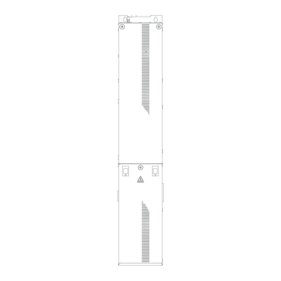
- Page 25 In the wall next to the hall door on the top floor (embedded) Back of the control panel 3.2.2 Plan Installation Space 3.2.2.1 Size See the figure below for overall size and installation size, unit: mm. 3-Ø10 161.5 Ø48 Figure 3-1 MTCC-V2A size MTCC-V2A Series User Manual V1.0...
- Page 26 MTCC-V2A uses forced air cooling for heat dissipation. To ensure the performance and life of MTCC-V2A, please leave enough installation space around MTCC-V2A. Figure 3-2 Installation space Table 3-2 Installation space ≥ 50mm ≥ 300mm ≥ 700mm MTCC-V2A Series User Manual V1.0...
- Page 27 Install the Lower Panel Door Installation steps: Press and hold the two buckles at the same time, place the panel door in the installation position, and then release the buckles. Use a Phillips screwdriver to tighten the screws clockwise. MTCC-V2A Series User Manual V1.0...
- Page 28 Remove the lower door of MTCC-V2A. For steps, refer to section 3.2.3.1, page 16. Fix MTCC-V2A onto the bolts. Use a socket wrench (13#) to tighten the hexagonal nut clockwise. Tightening torque: 9.0 - 10.0N·m. Expansion bolt Hex nut Wall MTCC-V2A (door removed) Figure 3-4 Install MTCC-V2A MTCC-V2A Series User Manual V1.0...
- Page 29 Mark the installation position on the wall and drill holes. The size is shown in the figure below (in mm). Fix the inspection box with the rubber plug screws. Use a Phillips screwdriver to tighten the screw clockwise. Tightening torque: 1.2 - 1.5N·m. 3-Ø5 Figure 3-5 Inspection box size MTCC-V2A Series User Manual V1.0...
- Page 30 Install 4 × M4 plastic expansion tubes into the holes. Fix the brake resistor box with screws. Use a Phillips screwdriver to tighten the screw clockwise. Tightening torque: 1.2 - 1.5N·m. 4-Ø5 Figure 3-6 Brake resistor box size MTCC-V2A Series User Manual V1.0...
- Page 31 Use 2 × M6 combination screws to fix the car top inspection box. Use a Phillips screwdriver to tighten the screw clockwise. Tightening torque: 4.0 - 5.0N·m. 2-Ø7 Figure 3-7 Car top inspection box size MTCC-V2A Series User Manual V1.0...
- Page 32 Up forced Dec. switch 80 - 200mm Leveling plate Down forced Dec. switch S > (2 × F03.12) Bottom floor leveling Down limit switch 30 - 50mm 150mm Down final limit switch Figure 3-8 Install the shaft switch MTCC-V2A Series User Manual V1.0...
- Page 33 S > end station leveling is the forced Dec. distance S. Calculation formula: 2 × F03.12 F03.12: Forced Dec., default value is 1m/s Rated Speed V (m/s) 0.25 0.75 First-level Forced Dec. Distance S (m) MTCC-V2A Series User Manual V1.0...
- Page 34 • Up final limit switch: Installed above the up limit switch, generally 150mm away from the top leveling position. • Down final limit switch: Installed below the down limit switch, generally 150mm away from the bottom leveling position. MTCC-V2A Series User Manual V1.0...
- Page 36 • Confirm that the AC power input voltage is the same as the rated input voltage of the control panel. • Do not connect the input power cable to the output U/V/W terminals. • It is prohibited to connect phase-shifting capacitors to the output circuit. MTCC-V2A Series User Manual V1.0...
- Page 37 Light curtain COB1/COB2 EDP1/EDP2 -A1/A2 (front /rear door) MT70-HCB COP communication (touch) MT70-CHM-D weighing device Voice intercom (use with CIC-GE) (digital) Lighting (bottom floor) Lower Lighting station (pit) Governor tension pulley Buffer Figure 4-1 System wiring MTCC-V2A Series User Manual V1.0...
- Page 38 The specifications of the power cable terminals are shown in the table below. Table 4-3 Power cable terminal data (code end terminal) Power Terminal Terminal Outer Diameter d (mm) L1, L2, L3, N ≤ 5 BR, + U, V, W MTCC-V2A Series User Manual V1.0...
- Page 39 L1, L2, L3, N Three phase AC power input L1, N Single phase AC power input BR, + Connect the brake resistor box (or brake resistor) U, V, W Three phase output, connected to motor Grounding MTCC-V2A Series User Manual V1.0...
- Page 40 Figure 4-3 Power terminal wring (single phase 220V) User power MTCC-V2A Brake resistor box Figure 4-4 Power terminal wring (three phase 220V) User power MTCC-V2A Brake resistor box Figure 4-5 Power terminal wring (three phase 380V) MTCC-V2A Series User Manual V1.0...
- Page 41 • Support pulse output encoder 1387 SINCOS encoder MT700-PG2-SINCOS Syn. motor • Support 5V • Support pulse output UVW encoder MT700-PG3-UVW Syn. motor • Support 5V 1313 absolute encoder MT700-PG4-SCG Syn. motor • Support pulse frequency division output MTCC-V2A Series User Manual V1.0...
- Page 42 • The encoder cable must be passed through a metal tube separately, and the metal casing must be reliably grounded. DB15 terminal Wiring hole (side) Wiring hole (back) Figure 4-6 DB15 and wiring holes MTCC-V2A Series User Manual V1.0...
- Page 43 • Short circuit 1, 2pin, power supply is +5V • Short circuit 2, 3pin, power supply is +12V (default) A, B Encoder signal A/B Grounding Unused Wiring PG1-ABZ Encoder Figure 4-8 MT700-PG1-ABZ wiring (open collector output or push-pull output) MTCC-V2A Series User Manual V1.0...
- Page 44 The parameter auto-tuning automatically learns the wiring mode of C+/- and D+/-, so the + and - phase sequence can be exchanged during wiring. That is, C+/- is exchanged to C-/+, and D+/- is exchanged to D-/+. MTCC-V2A Series User Manual V1.0...
- Page 45 Encoder differential signal W 13, 14 PGVCC, PGGND +5V Power Supply Wiring The DB15 terminal connects to the DB15 male connector of the encoder cable. See section 4.3.2, page 31 for the connection location of DB15 terminal. MTCC-V2A Series User Manual V1.0...
- Page 46 Encoder differential data signal 13, 14 PGVCC, PGGND +5V power supply Wiring The DB15 terminal connects to the DB15 male connector of the encoder cable. See section 4.3.2, page 31 for the connection location of DB15 terminal. MTCC-V2A Series User Manual V1.0...
- Page 47 Table 4-11 Indicator description Indicator Description Safety circuit indicator in the 111 (green) control panel On: Safety circuit connected 121 (green) Shaft safety circuit indicator Off: Safety circuit disconnected 123 (green) Car safety circuit indicator MTCC-V2A Series User Manual V1.0...
- Page 48 Up forced Dec. (default) DLS (X11) Down forced Dec. 20, 22 111, 121 Shaft safety circuit Shaft safety switch Pit EEO short-circuit point 1, 2 501, 502 Lighting power L/N User power box Power cable MTCC-V2A Series User Manual V1.0...
- Page 49 2, 3 301, 302 DC 24V/0V Spare 4, 5 Y8, M9 Output 1, 2 302, 301 Governor power DC 24V Governor (default Governor AC 220V) cable 4, 5 208, 207 Governor power AC 220V 1 23 MTCC-V2A Series User Manual V1.0...
- Page 50 The forced Dec. switch is installed in the shaft by default, connect interface BA. Interface Description Wiring 16, 18 DC 24V Forced Dec. switch ULS (X10) Up forced Dec. Shaft (default) cable DLS (X11) Down forced Dec. MTCC-V2A Series User Manual V1.0...
- Page 51 After 3s, the display stops flashing, press the Up or Down button to set the target floor address. Wait for 5s, HCB flashes to display the floor again, the setting is successful. After 3s, HCB displays normally. Set F26.31 = 0. MTCC-V2A Series User Manual V1.0...
- Page 52 Set the power supply to 24VDC by interface K4: Remove the short-circuit cable on 4, 5pin, and then short-circuit 1, 2pin. Interface Description Wiring Governor power DC 1, 2 302, 301 Governor (default AC Governor 220V) Governor power AC cable 4, 5 208, 207 220V MTCC-V2A Series User Manual V1.0...
- Page 53 Relay output indicator CY12 - CY20 (green) Off: Relay has no output LIGHT [CY1] (green) Lighting output indicator On: Fan or lighting is off Off: Fan or lighting is on FAN [CY11] (green) Fan output indicator MTCC-V2A Series User Manual V1.0...
- Page 54 1, 2 207A, 208 AC220V L/N CTS5 220VAC power Ground Acousto-optic alarm 1, 2 303, 302 power Acousto-optic alarm 3, 4 301/12V DC 24V/12V DC 0V Leveling sensor (optional) 3, 4 FL1, FL2 No function MTCC-V2A Series User Manual V1.0...
- Page 55 1, 9, 10 CD or OD (com) Forced close door DEN2 Door controller [rear door] 4, 5 CY6, CY5 CD/OD (close/open door) DCA or DOA (com) DCA/DOA (door close/ 7, 8 CX6, CX4 open arrived) MTCC-V2A Series User Manual V1.0...
- Page 56 FL1, FL2 No function Interface AA 12, 13 Traveling cable (low 14, 15 CAN+, CAN- CAN communication voltage) 16, 17 R, L Intercom R/L 24V2 DC 24V (spare) Up/down forced Dec. 19, 20 X14, X15 (optional) MTCC-V2A Series User Manual V1.0...
- Page 57 L/N Control panel interface Fan, lighting power board 2, 11 507, 508 MTCC-KCB-D2A Ground Interface AA Traveling cable (high 6, 17 130, 123 Car top safety circuit voltage) EEO safety circuit bypass (end) MTCC-V2A Series User Manual V1.0...
- Page 58 X15 terminal function Front door safety edge signal F13.26 Y2 relay function 1 (default) Front door open output F13.27 Y3 relay function 2 (default) Front door closed output F13.27 Y4 relay function Front door forced close MTCC-V2A Series User Manual V1.0...
- Page 59 Rear door safety edge signal Rear door motor overheat (normally H01.45 X19 terminal function closed) F13.29 Y5 relay function Rear door open output F13.30 Y6 relay function Rear door close output F13.31 Y7 relay function Rear door forced close MTCC-V2A Series User Manual V1.0...
- Page 60 • If photoelectric sensor switch (NPN) is used, connect 1, 2, 3 pin. Interface Description Wiring 301/12V DC 24V/12V DC 0V Leveling sensor Up leveling See below for parameter settings. Ref. Code Function Meaning H01.01 X9 terminal function 33 (default) Door zone MTCC-V2A Series User Manual V1.0...
- Page 61 Fan power N/L Ground Lighting 4, 8 502, 510 Lighting power N/L See below for parameter settings. Ref. Code Function Meaning F13.25 Y1 relay function 40 (default) Lighting output H01.16 Y11 relay function 39 (default) Fan output MTCC-V2A Series User Manual V1.0...
- Page 62 If the electronic safety gear is used, connect to interface CST1. Interface Description Wiring CY12 Output CTS1 Relay output (spare) Output (com) See below for parameter settings. Ref. Code Function Meaning Unintended car movement in the leveling H01.17 Y12 relay function zone MTCC-V2A Series User Manual V1.0...
- Page 63 MTCC-KCB-D2A Interface AB SPK1, SPK2 Speaker +/- Traveling cable (voice intercom) 1, 4 301, 302 DC 24V/0V 2, 5 SP1, SP2 Microphone +/- MT70-CHM-D (for use with CIC-GE) 3, 6 SPK1, SPK2 Speaker +/- MTCC-V2A Series User Manual V1.0...
- Page 64 • a. Tighten the antenna clockwise onto the antenna interface. • b. Folding antenna (optional). Antenna Antenna interface Figure 4-14 Connect the antenna Connect the Antenna of the MT70-CIC-EO The steps are the same as CIC-GE. MTCC-V2A Series User Manual V1.0...
- Page 65 Make sure the cables are routed separately. • Encoder cables and power cables. • Communication cables and power cables. Confirm that the shaft is clear, the car is unoccupied, and the conditions for safe running of the elevator are met. MTCC-V2A Series User Manual V1.0...
- Page 66 Quick debug, monitor elevator status, set parameters, and view fault Android phone details. [Bluetooth debugging MTCC-V2A connects to the Bluetooth module (MT70-BLE-A) and installs APP] the Bluetooth debugging APP on the Android phone. MTCC-V2A Series User Manual V1.0...
- Page 67 • When dialed to I, the system is powered on; When dialed Main Power Supply to O, the system is powered off Switch • Power off condition: Door close arrived is valid, door lock and leveling signal are valid • Without AC power: MTCC-V2A Series User Manual V1.0...
- Page 68 The LED is located on the inspection box, and the LED definition is shown in the figure below. Figure 5-2 LED definition Display Fault When MTCC-V2A reports a fault, the LED alternately displays: Fault (rolling display EXX), system status. MTCC-V2A Series User Manual V1.0...
- Page 69 CX19 CX20 CY: Output CY10 CY11 CY12 CY13 CY14 Exit the menu interface: When the LED displays page 9, press the MENU button to exit the menu interface, and the LED displays the system status. MTCC-V2A Series User Manual V1.0...
- Page 70 • In the inspection status, press and hold the UP and RUN DOWN Button buttons at the same time, the elevator runs up • In the inspection status, press and hold the DOWN and RUN buttons at the same time, the elevator runs down MTCC-V2A Series User Manual V1.0...
- Page 71 • Press this key to cycle through the status parameters • Press this key to move the parameter or parameter value to the right Shift • Press this key to cycle through the status parameters MTCC-V2A Series User Manual V1.0...
- Page 72 After MTCC-V2A is powered on or when there is no key operation on the keypad within 5 minutes, the keypad displays the “Enter password”, see the figure below. Unlock password, see section 5.3.3.4, page 67. 【Enter p assword】 0 0 0 0 Figure 5-6 Enter password display interface MTCC-V2A Series User Manual V1.0...
- Page 73 When the elevator is running or stopped, the keypad displays the “Status display”, see the figure below, and see the table below for description. Automatic Single 0000 0280 97 5/6/7 1.0 0 0m/s Door open O verload arrived Figure 5-8 Status display interface MTCC-V2A Series User Manual V1.0...
- Page 74 Display: Overload, full load. [D05.00 Bit12/Bit13] Display: Light curtain. Light curtain status When there are front and rear doors, the status includes "front door” [D05.00 Bit0/Bit1] or "rear door", such as: Front door light curtain. 1213 MTCC-V2A Series User Manual V1.0...
- Page 75 Cycle 【F0 0.00】 【F00.10】 Parameter ..(third level) Mot or type Elevator runn ing direction 【F0 0.00】 【F00.00】 Parameter value (fourth level) A syn. m otor Syn. mot or Figure 5-9 Switch the four-level menu MTCC-V2A Series User Manual V1.0...
- Page 76 Invalid parameter group: parameters: Unit, ten long press to quickly Unit, ten switch Cycle through the Cycle switching Cycle switching parameter values, Invalid parameter group: parameters: Unit, ten long press to quickly Unit, ten switch MTCC-V2A Series User Manual V1.0...
- Page 77 【F26.35】 【F26.35】 =1111 1111 1111 1111 =1111 1111 1111 1111 Hall call p arameter Bit0: Digital arrow Bit10: Hall call display fixed bo ard display fault code Figure 5-11 Fast switching of 16-bit binary numbers MTCC-V2A Series User Manual V1.0...
- Page 78 En cr yp tion succ essful Figure 5-13 Change user password 5.3.3.6 Clear User Password Set F01.00 = 00000, press the ENT key. When the keypad displays “Password has been cleared”, the password has been cleared successfully. MTCC-V2A Series User Manual V1.0...
- Page 79 Keypad p arameter update Figure 5-15 Download parameter E22 Troubleshooting When uploading or downloading parameters, if MTCC-V2A reports E22 fault, the upload or download of parameters fails. For troubleshooting, see section 10.3.22, page 208. MTCC-V2A Series User Manual V1.0...
- Page 80 • High-resolution LCD: Display more information. • Debugging is more convenient: The parameter menus are divided according to application situation, and application macros (parameter sets, such as basic parameters, motor auto-tuning, leveling, comfort, etc.) are added. Display Figure 5-16 MT70-LCD-C MTCC-V2A Series User Manual V1.0...
- Page 81 Hall call bo ard soft ware: 9.99 Elevator int egrated Operator soft ware: 1.00 controller Main control bo ard non-s tandard: 0.00 C ar top bo ard non-standard: 0.00 Hall call bo ard non-s tandard: 0.00 Figure 5-17 Power-on display interface MTCC-V2A Series User Manual V1.0...
- Page 82 Parallel mode Display: Single elevator. Number of runs Display the number of elevator runs. Current floor Display the current floor of the elevator : The elevator runs up. Running direction : The elevator runs down. MTCC-V2A Series User Manual V1.0...
- Page 83 Curve display Curve Display elevator running speed display Self- Motor parameters and shaft parameter Self-learning System Application learning self-learning information macro System Software version, non-standard version information Application Collection of parameters for various macro applications MTCC-V2A Series User Manual V1.0...
- Page 84 Parameters of elevator enhancement ment test mainten ance Configuration Hardware and accessory card parameters test Verify menu Elevator Repair and maintenance parameters maintenance Display parameters that are different from Verify menu factory values (F01.01 = 1) MTCC-V2A Series User Manual V1.0...
- Page 85 Equipped with MT70-BLE-A (Bluetooth module), use an Android phone (operating system Android4.3 and above) to debug MTCC-V2A and monitor the elevator system. Please download the apk program from ww.hpmont.com: Download Center > Application Software > MONT70 Bluetooth Debugging, and then install the Bluetooth Debugging APP (hereinafter referred to as APP).
- Page 86 Run times Display the number of elevator runs. Fire return Automatic Automatic Inspection base Firemen Driver return to Elevator running station leveling mode Independe Emergency Door lock Door lock open Door lock close MTCC-V2A Series User Manual V1.0...
- Page 87 Example: Display E51, 03. MTCC-V2A reports E5103 fault (shaft self- Fault code, subcode learning fault). Click the fault code to enter the “Current fault information” interface. Red: Fault reset is valid, click Fault reset No fault to reset the fault MTCC-V2A Series User Manual V1.0...
- Page 88 Chapter 5 Debugging Tool 5.5.4 Elevator Call Interface Description Click the button in the upper right corner of the “Monitoring” interface to enter the “Call” interface, see the figure and table below for instructions. Figure 5-21 Call interface MTCC-V2A Series User Manual V1.0...
- Page 89 Elevator fault Gray: No fault fault. Click to enter the “Current Fault display” Overload/full load Gray: No overload Red: Overload Door lock Door lock open Door lock close Leveling Leveling is invalid Leveling is valid MTCC-V2A Series User Manual V1.0...
- Page 90 See section 6.6 for details. High-speed running See section 6.7 for details. Adjust comfort See section 6.8 for details. Adjust leveling See section 6.9 for details. Test brake force function See section 6.10 for details. MTCC-V2A Series User Manual V1.0...
- Page 91 [0.1 - 400.0kW] F10.02 Rated voltage [0 - 999V] Set according to the motor F10.03 Rated current [0.0 - 999.9A] nameplate F10.04 Rated frequency 19.20 [1.00Hz - F00.05] F10.05 Rated rpm 96 [1 - 24000rpm] MTCC-V2A Series User Manual V1.0...
- Page 92 19: Down forced Dec. (DLS1) 24: Fire (FIRS1) X9 terminal F12.09 function 25: Fireman switch (FIRS2) 26: Front door light curtain (EDP1) X10 terminal 27: Rear door light curtain (EDP2) F12.10 function 28: Emergency running (UPC) MTCC-V2A Series User Manual V1.0...
- Page 93 1: Run contactor output 2: Brake contactor output 3: Door-closed contactor output 4: Syn. star-delta contactor output 5: Brake forced output F12.29 Y2 relay function 6: Front door open 7: Front door close 8: Rear door open MTCC-V2A Series User Manual V1.0...
- Page 94 6: Rear door light curtain 7: Full load signal X5 terminal F13.05 8: Overload signal function 9: Door open button X6 terminal 10: Door close button F13.06 0 [105] function 11: Door open delay button MTCC-V2A Series User Manual V1.0...
- Page 95 59: Rear door motor overheat X19 terminal H01.45 0 [159] 60: External emergency stop signal function 63: Self-rescue run input 65: Car call input prohibited X20 terminal H01.46 0 [0 - 166] 66: Self-rescue input prohibited function MTCC-V2A Series User Manual V1.0...
- Page 96 Y11 relay H01.16 42: Non-automatic mode output function 45: Phone output 46: Call display 50: Up leveling valid output Y12 relay H01.17 0 [27] 51: Down leveling valid output function 52: Door zone valid output MTCC-V2A Series User Manual V1.0...
- Page 97 Time parameters actual setting • If it does not match, please reset it Set Control Mode Ref. Code Parameter Default [Range] Description 0: Keypad control F00.07 Operation method 1 [0, 1] 1: Distance control MTCC-V2A Series User Manual V1.0...
- Page 98 • The motor does not rotate and makes a whistling sound that lasts for about 30s. Auto-tuning ends: The keypad does not display “Motor auto-tuning”. Confirm that the auto-tuning is successful: MTCC-V2A does not report any fault. Set F00.07 = 1 (distance control). MTCC-V2A Series User Manual V1.0...
- Page 99 Auto-tuning process: • The keypad displays “Motor auto-tuning”. • The run contactor is closed. • The motor made a humming sound and then rotated one circle at a low speed. MTCC-V2A Series User Manual V1.0...
- Page 100 Countermeasure: Invert the value of F11.02 (encoder direction), then perform auto-tuning again. During auto-tuning, MTCC-V2A reports E12 fault (parameter auto-tuning fault). Countermeasure: Check the wiring of the motor, confirm that the wiring is correct, then perform auto-tuning again. MTCC-V2A Series User Manual V1.0...
- Page 101 If the signal valid order is wrong, check the external wiring and parameter settings. The elevator exits the emergency electric mode: Release the buttons and rotate the EEO/NORMAL switch on the inspection box to NORMAL. MTCC-V2A Series User Manual V1.0...
- Page 102 The elevator exits maintenance mode: Release the buttons and and rotate the NORMAL/INS switch on the car top inspection box to NORMAL. MTCC-V2A Series User Manual V1.0...
- Page 103 • Check D06.06 (number of leveling switches), D06.07 (length between leveling switches), and D06.08 (leveling plates length) to confirm that they are consistent with the actual situation. The elevator exits the emergency electric mode: Rotate the EEO/NORMAL switch on the inspection box to NORMAL. MTCC-V2A Series User Manual V1.0...
- Page 104 • Front door safety edge: D05.00 Bit14 = 1. • Rear door safety edge: D05.00 Bit15 = 1. The elevator exits inspection mode: Rotate the NORMAL/INS switch on the car top inspection box to NORMAL. MTCC-V2A Series User Manual V1.0...
- Page 105 0 - F19.00 F19.00 Total floors 2 - 8 1 23 Confirm that the high-speed test run is correct: The elevator can open and close doors, accelerate and decelerate, call the elevator, and stop normally. MTCC-V2A Series User Manual V1.0...
- Page 106 Connect the leveling signal cable. Test Overload Function Test steps: Manually activate the elevator overload switch and confirm: • The elevator door cannot be closed. • The buzzer in the car sounds. • The car call board displays “overload”. MTCC-V2A Series User Manual V1.0...
- Page 107 • The elevator automatically closes the door, starts, and runs at high speed. • When the elevator reaches the called floor, it automatically slows down, stops, cancels the hall call (consistent with the stop floor), and opens the door. MTCC-V2A Series User Manual V1.0...
- Page 108 • When the system detects 2 leveling signals (up and down), after F26.30 time, the elevator decelerates from 0.200m/s to zero speed, stops and opens the door. Related parameters: Ref. Code Parameter Range Recommend Default Return to level stop F26.30 0.000 - 3.000s 0.100s 0.100s delay MTCC-V2A Series User Manual V1.0...
- Page 109 Confirm that the brake opening gap is sufficient. If friction occurs, adjust the brake gap. Confirm that the brakes on both sides of the brake are Syn.. If not, adjust them to Syn.. MTCC-V2A Series User Manual V1.0...
- Page 110 0.200m/s F03.03 Dec. 0.020 - 2.000m/s 0.500m/s Dec. rate of change Rapid Dec. at the F03.04 0.020 - 2.000m/s 0.200m/s beginning Rate of change of Dec. Rapid Dec. at the F03.05 0.020 - 2.000m/s 0.200m/s MTCC-V2A Series User Manual V1.0...
- Page 111 1 - 9999 Jitter within F08.04: increase F08.01 Low speed loop KI 1 - 9999 F08.00/F08.01 Jitter above F08.05: increase F08.02 High speed loop KP 1 - 9999 F08.02/F08.03 F08.03 High speed loop KI 1 - 9999 MTCC-V2A Series User Manual V1.0...
- Page 112 Check whether the line is Rewire normal Adjustment [2] Possible Causes Detection Method Countermeasures The forced Dec. switch is Check the installation distance installed at the wrong Adjust the installation distance of the switch distance MTCC-V2A Series User Manual V1.0...
- Page 113 Possible Causes Detection Method Countermeasures Door lock disconnected Check the gap between the Adjust the gap when stop door blade and the door ball Adjustment [2] Possible Causes Detection Method Countermeasures System fault View fault Troubleshooting MTCC-V2A Series User Manual V1.0...
- Page 114 Adjustment [5] Possible Causes Detection Method Countermeasures After closing the brake device, Stop noise Decrease F16.00 the motor still makes noise Ref. Code Parameter Range Default Description Stop current F16.00 0 - 1500ms 350ms removal time MTCC-V2A Series User Manual V1.0...
- Page 115 1: F03.15 adjusts the up leveling, and F03.16 adjustment adjusts the down leveling Up leveling distance F03.15 0 - 60mm 30mm adjustment Down leveling distance F03.16 0 - 60mm 30mm adjustment Leveling distance F19.03 0 - 60mm 30mm adjustment MTCC-V2A Series User Manual V1.0...
- Page 116 • Up less-leveling: Increase the 2 digits on the far left of F27.02. 1st up/down leveling • Down higher-leveling: Increase the 2 digits on the far right of adjust F27.02. Up Down • Down less-leveling: Decrease the 2 digits on the far right of F27.02. MTCC-V2A Series User Manual V1.0...
- Page 117 After debugging all the up leveling, press the top and bottom elevator call buttons at the same time. The elevator close the door, then runs up to the top floor and open the door. Exit car adjustment: Press the top and bottom elevator call buttons at the same time. MTCC-V2A Series User Manual V1.0...
- Page 118 Brake detection torque 60 - 150% 120% F04.16 Brake detection allowable pulse 1 - 99 F04.17 Number of successful brake detections 0 - 65535 F25.04 0: Do not start Brake force test Bit8 1: Start MTCC-V2A Series User Manual V1.0...
- Page 120 1: Judge based on weighing signal Bit3: Emergency running direction fixed up Bit4: Emergency running direction fixed down 0: Not set by this Bit 1: Fixed Bit5: Automatically switch to drive 0: Disable 1: Enable MTCC-V2A Series User Manual V1.0...
- Page 121 1: Provided by external ARD Bit14: Dec. to stop mode 0: Dec. to stop when encountering up or down leveling 1: Dec. to stop immediately when encountering leveling Bit15: Emergency running torque limit 0: F08.09 setting 1: F02.08 setting MTCC-V2A Series User Manual V1.0...
- Page 122 Open the elevator door: • With AC power: The elevator opens the door automatically. • Without AC power: Professionals manually open the elevator door. MTCC-V2A Series User Manual V1.0...
- Page 123 Use Low Voltage Door Lock Signal Parameter Setting Low voltage door lock signal F12.19 X19 = 6 Low voltage solenoid valve feedback signal F12.20 X20 = 7 MTCC-V2A Series User Manual V1.0...
- Page 124 7: Door lock circuit 2 (hall door MCB board X20 terminal F12.20 lock) function F13.25 CTB board Y1 relay function 31 : Solenoid valve output 39: Fan output CTB board Y11 relay H01.16 40: Lighting output function MTCC-V2A Series User Manual V1.0...
- Page 125 • F26.10 Bit11 = 1, unit: s F26.10 0: min Car lighting fan energy saving time unit Bit11 1: s F27.28 0: Do not process Manual door light curtain Dec. to stop Bit5 1: Dec. to stop MTCC-V2A Series User Manual V1.0...
- Page 126 Set the heights of other floors in sequence: After setting all floors, H03.01 automatically changes to 0 (exit magnetic scale shaft learning). The elevator exits inspection mode: Rotate the EEO/NORMAL switch on the inspection box to NORMAL. MTCC-V2A Series User Manual V1.0...
- Page 127 Call the elevator to the 3rd floor. b. Set H03.02. • If the higher-leveling is 20mm: Set H03.02 = 80. • If the less-leveling is 20mm: Set H03.02 = 120. Set H03.03 = 3 (adjust floor). Continue adjusting other floors. MTCC-V2A Series User Manual V1.0...
- Page 128 The magnetic scale status monitoring parameters are shown in the table below. Please set H03.49 = 4 first. Ref. Code Parameter Range Default Magnetic scale configuration D07.83 status Maximum value of magnetic 0 - 65535 ( × 2ms) D07.84 scale communication abnormality MTCC-V2A Series User Manual V1.0...
- Page 129 1: Initialization successful Bit9: Display content of the number of runs and position on the keypad 0: Magnetic scale position 1: Number of runs Bit10: Inspection of up and down limits of shielded magnetic scale simulation MTCC-V2A Series User Manual V1.0...
- Page 130 Absolute position of the first H03.05 0 - 400m × floor (high bit) Absolute position of the first × H03.06 0 - 999mm floor (low bit) Magnetic scale leveling plate H03.09 80 - 400mm 100mm × length MTCC-V2A Series User Manual V1.0...
- Page 131 Magnetic scale 8th floor H03.48 0 - 65535 × height MCB board X19 terminal F12.19 function 6: Door lock circuit 1 (car door lock) 7: Door lock circuit 2 (hall door lock) MCB board X20 terminal F12.20 function MTCC-V2A Series User Manual V1.0...
- Page 132 -10 - +50 ℃, 40 - 50 ℃ needs to be derated Temperature Humidity Less than 95%RH, no condensation Operating Dust No accumulation of conductive dust environment Water and dripping No trace of water leakage Odorless Control panel Vibration Smooth vibration MTCC-V2A Series User Manual V1.0...
- Page 133 3. For control panels stored for a long time, please power on once within 2 years. Use a voltage regulator to slowly increase the input voltage of the control panel to the rated value and keep it powered on for at least 5 hours. MTCC-V2A Series User Manual V1.0...
- Page 134 • Burning the electrolytic capacitors inside the control panel may cause an explosion. • Burning plastic parts produces toxic gases, please dispose of them as industrial waste. • Lead-acid batteries are highly polluting items. Please submit them to a recyclable repair shop or other specialized recycling agency. MTCC-V2A Series User Manual V1.0...
- Page 136 MCB board, please contact the agent or our company. Parameter Setting Mode [Set]: *: Actual parameters, cannot be modified. × : Parameters cannot be modified when MTCC-V2A is running. ○ : Parameters can be modified when MTCC-V2A is running. MTCC-V2A Series User Manual V1.0...
- Page 137 Bit5: Door lock circuit 1 Main control board input D02.03 Actual logic status 1 Bit6: Door lock circuit 2 Bit7: Running output feedback Bit8: Brake output feedback Bit9: Inspection Bit10: Inspection up Bit11: Inspection down MTCC-V2A Series User Manual V1.0...
- Page 138 Bit8: Rear door close Bit9: Lighting fan output Bit10: Fault output Bit11: Power failure emergency running Bit12: Fire linkage output Bit13: Medical disinfection output Bit14: Electric lock output Bit15: Non-door zone stop output MTCC-V2A Series User Manual V1.0...
- Page 139 Bit1: Front door close output Bit2: Rear door open output Car top board output logic D03.05 Actual status 1 Bit3: Rear door close output Bit4: Up car arrival chime output Bit5: Down car arrival chime output MTCC-V2A Series User Manual V1.0...
- Page 140 Hall call up registration 1: The floor where this address is located is D04.07 Actual status registered 0: There is no registration on the floor where this address is located D04.08 - D04.09: Manufacturer debugging parameters MTCC-V2A Series User Manual V1.0...
- Page 141 Bit3: Fire hall call Bit7 - Bit4: Elevator status 0000: Automatic D05.00 Elevator system status 0001: Inspection Actual 0010: Emergency 0011: Shaft self-learning 0100: Fire return to base station 0101: Fireman mode 0110: Driver mode 0111: Independent MTCC-V2A Series User Manual V1.0...
- Page 142 Actual Number of leveling D06.06 1 - 2 Actual switches Length between leveling D06.07 0 - 999mm Actual switches D06.08 Leveling plate length 0 - 999mm Actual D06.09 Encoder pulse count 0 - 65535 Actual MTCC-V2A Series User Manual V1.0...
- Page 143 Bit6: Emergency running completed Bit7: Emergency rescue buzzer output Bit8: Governor output Bit9: Unused Bit10: Solenoid valve output Bit11: External energy feedback fault reset output Bit12 - Bit15: Unused D06.16 HDRU feedback power 0.00 - 999.99kW Actual MTCC-V2A Series User Manual V1.0...
- Page 144 Bit3: Bypass input Bit4: HDRU fault input signal Main control board input D06.55 Actual logic status 4 Bit5: UPS fault input signal Bit6: Emergency electric running Bit7: Main switch disconnects input signal Bit8 - Bit9: Unused MTCC-V2A Series User Manual V1.0...
- Page 145 Maximum pulse of zero D06.74 0 - 65535 Actual servo start slip D06.75 - D06.86: Manufacturer debugging parameters Bit0: ARD run indication 0: Run ARD or inspection box D06.87 Actual 1: Stop status Bit1: ARD fault indication MTCC-V2A Series User Manual V1.0...
- Page 146 D06.92 corresponding to the Actual 0111: Run independently current fault 1 1000: Automatically return to leveling 1001: VIP running Bit4: Excessive position deviation return to base station 0: Invalid 1: Valid Bit5 - Bit15: Unused MTCC-V2A Series User Manual V1.0...
- Page 147 Bit1: Up leveling signal Bit2: Down leveling signal Bit3: Front door switch prohibited D06.97 Car top board input logic 3 Bit4: Unused Actual Bit5: Fan and lighting off Bit6 – Bit9: Unused Bit10: Up forced Bit11: Down forced MTCC-V2A Series User Manual V1.0...
- Page 148 00000 - 65535 12345 0: Standard menu mode 1: Verify menu mode (parameters different F01.01 Menu mode ○ from factory values) 2: Unused 0: No operation Main control board F01.02 × parameter update 1: Restore factory parameters MTCC-V2A Series User Manual V1.0...
- Page 149 Rapid Acc. at the end 0.020 - 2.000m/s 0.200m/s × F03.03 Dec. 0.020 - 2.000m/s 0.500m/s × F03.04 Rapid Dec. at the beginning 0.020 - 2.000m/s 0.200m/s × F03.05 Rapid Dec. at the end 0.020 - 2.000m/s 0.200m/s × MTCC-V2A Series User Manual V1.0...
- Page 150 Excessive speed deviation F04.11 5.0 - 30.0% (F00.03) 20.0% × detection value Excessive speed deviation F04.12 0.1 - 2.0s 1.0s × detection time F04.13 Manufacturer debugging parameters F04.14 Brake detection duration 3 - 10s × MTCC-V2A Series User Manual V1.0...
- Page 151 × coefficient F05.17 No weighing speed loop KP 1 - 9999 ○ F05.18 No weighing speed loop KI 1 - 9999 ○ F06: Motor performance control parameters Performance optimization × F06.00 Bit0: Unused 0x0507 parameters MTCC-V2A Series User Manual V1.0...
- Page 152 F06.03 - F06.05: Manufacturer debugging parameters F07: Asyn. motor parameters F07.00 Asyn. motor rated power 0.1 - 500.0kW × Depend F07.01 Asyn. motor rated voltage 0 - 999V × on V2A F07.02 Asyn. motor rated current 0.0 - 999.9A × MTCC-V2A Series User Manual V1.0...
- Page 153 Bit1: Excitation current optimization method 0: Voltage 1: Current Asyn. motor performance Bit2: Asyn. pre-torque compensation new F07.20 × optimization algorithm 0: Invalid 1: Valid Bit3: Dec. point processing Bit4: Rotor resistance identification frequency 0: Optimization MTCC-V2A Series User Manual V1.0...
- Page 154 0.000 - 0.256s Speed loop output filter F08.08 0.000s ○ time 0.000: Speed loop output is not filtered F08.09 Torque limit 0.0 - 200.0% (motor rated current) 180.0% × F09: Vector control current loop parameters MTCC-V2A Series User Manual V1.0...
- Page 155 2048 × offset SINCOS encoder D F10.16 0 - 4095 2048 × amplitude SINCOS encoder D zero F10.17 0 - 4095 2048 × offset 0: Normal SINCOS encoder CD phase F10.18 × sequence 1: Opposite MTCC-V2A Series User Manual V1.0...
- Page 156 11: Below 1/2 rated speed Bit11: SINCOS encoder low speed subdivision 0: Calculate once per carrier cycle 1: Bit8 sets the calculation cycle Bit12: Angle learning speed of Syn. motor auto-tuning 0: Slow 1: Fast Bit13: Current sampling optimization MTCC-V2A Series User Manual V1.0...
- Page 157 10: Inspection (INS) 11: Inspection up (UP) F12.05 MCB X5 terminal function × 12: Inspection down (DN) 13: Up limit (LSU) 14: Down limit (LSD) F12.06 MCB X6 terminal function × 15: Lock elevator (LOCK) MTCC-V2A Series User Manual V1.0...
- Page 158 MCB X21 terminal function × 65: Self-rescue running feedback 66: Self-rescue running 74: Brake 2 feedback F12.22 MCB X22 terminal function × 76: Base station hall call prohibited service F12.23 - F12.27: Manufacturer debugging parameters MTCC-V2A Series User Manual V1.0...
- Page 159 Bit0: Manual door lock disconnected car and hall call display 0: Normal display 1: Manual door reminder display Manual door advanced F12.38 0x12c3 × parameters Bit3 - Bit1: Solenoid valve pull-in time Bit6 - Bit4: Solenoid valve disconnection time 000: 1s MTCC-V2A Series User Manual V1.0...
- Page 160 Unit: Car top board input filter time 0: 4ms 1: 10ms 2: 20ms 3: 30ms Car top board and car ○ F13.00 4: 40ms command filtering 5: 50ms 6: 60ms 7: 70ms 8: 80ms 9: 100ms MTCC-V2A Series User Manual V1.0...
- Page 161 27: VIP running in the car 28: Car door closing detection switch Main COP command board F13.15 × 29: Inspection X7 input function 30: Inspection up Main COP command board F13.16 × 31: Inspection down X8 input function MTCC-V2A Series User Manual V1.0...
- Page 162 Main COP command board F13.35 × X 4 output function 24: Front door forced closing signal output 25: Rear door forced closing signal output Main COP command board F13.36 × 26: Car arrival chime output X5 output function MTCC-V2A Series User Manual V1.0...
- Page 163 2: 1-8-1 format, odd parity, RTU F14.00 Data format × 3: 1-7-2 format, no parity, ASCII 4: 1-7-1 format, even parity, ASCII 5: 1-7-1 format, odd parity, ASCII 0: 1200bps 1: 2400bps F14.01 Baud rate × 2: 4800bps 3: 9600bps MTCC-V2A Series User Manual V1.0...
- Page 164 Bit7: No call elevator opens the door after the light curtain decelerates to stop and return to the level floor in manual door mode 0: Do not open the door 1: Open the door Bit8, Bit9: Unused Bit10: Child lock function MTCC-V2A Series User Manual V1.0...
- Page 165 1: High priority Bit8: Unintended car movement protection in inspection mode 0: Disable 1: Enable Bit9: Inspection box series 0: COOL100 series 1: V2 series Bit10:Mains electric brake release 0: Disable 1: Enable Bit11: Unused MTCC-V2A Series User Manual V1.0...
- Page 166 Stop and current removal F16.00 0 - 1500ms 350ms × time 0: Automatically stop 1: Stop immediately ○ F16.01 Cooling fan control 2: The fan keeps running after powering on 3: Automatically control according to module temperature MTCC-V2A Series User Manual V1.0...
- Page 167 × F16.14 - F16.24 Manufacturer debugging parameters F17: Fault protection parameters Input phase loss detection F17.00 0 - 100% (controller rated voltage) × reference Input phase loss detection F17.01 0.0 - 5.0s 1.0s × time MTCC-V2A Series User Manual V1.0...
- Page 168 1: Disable Bit7: Fault relay action during inspection 0: No action 1: Action Bit8: Unused Bit9: Star-delta feedback detection before start 0: Detection 1: Do not detect Bit10: Brake switch fails 3 times 0: No processing MTCC-V2A Series User Manual V1.0...
- Page 169 E22: Keypad EEPROM read/write abnormality (only displayed on the keypad) F17.14 The 4th fault E23: Parameter setting error E24: Input cable voltage detection fault E28: ARD fault E30: Encoder reverse E31: Encoder disconnection MTCC-V2A Series User Manual V1.0...
- Page 170 E60: Forced Dec. distance is too short F17.22 The 8th fault E62: Overcurrent during inspection running E63: Abnormal advanced door open E64: Slidding fault E66: Brake force self-test fault MTCC-V2A Series User Manual V1.0...
- Page 171 Time of the 8th fault F17.23 (month/day) Time of the 9th fault F17.25 (month/day) Time of the 10th fault F17.27 (month/day) F17.28 Latest fault 00 - 99 0000 Time of the last fault F17.29 0101 - 1231 0000 (month/day) MTCC-V2A Series User Manual V1.0...
- Page 172 × 0 - 50000 Floor height = F20.02 Floor height 2 (high bit) × 50000 × high floor + low floor F20.03 Floor height 2 (low bit) × F20.04 Floor height 3 (high bit) × MTCC-V2A Series User Manual V1.0...
- Page 173 Bit0 – Bit7: Floor 1 - 8 Bit8 - Bit15: Unused Time-sharing service 2 F21.17 65535 ○ service floor 0: Service floor, stop is allowed 1: Non-service floor, stop is prohibited F21.18 - F21.19: Manufacturer debugging parameters MTCC-V2A Series User Manual V1.0...
- Page 174 0: Close the door normally 1: Open the door of the base station and F22.13 Waiting door status wait for the elevator ○ 2: Open the door and wait for the elevator on each floor MTCC-V2A Series User Manual V1.0...
- Page 175 ○ F24.02 Floor 2 display 1902 01: 1 31: O 02: 2 32: Q 03: 3 33: S 04: 4 34: T F24.03 Floor 3 display 1903 05: 5 35: U 06: 6 36: V MTCC-V2A Series User Manual V1.0...
- Page 176 0: Disable 1: Enable ○ F25.04 Special test parameters Bit3: Limit enable 0: Enable 1: Disable Bit4: Random running enable 0: Disable 1: Enable Bit5: Floor-by-floor test runs for 3 hours Bit6: Simulate overload switch action MTCC-V2A Series User Manual V1.0...
- Page 177 1: Does not open the door automatically Bit4: Unused Bit5: The first time the driver enters the clear car and call calls 0: Do not clear 1: Clear Bit6: Driver mode responds to hall call 0: Response MTCC-V2A Series User Manual V1.0...
- Page 178 1: Press the button once to start the fan and stop after running for F16.06 time F26.03 Fire function × Door open re-leveling 0: Disable F26.04 × function 1: Enable Advanced door open F26.05 × function MTCC-V2A Series User Manual V1.0...
- Page 179 1: Dec. to stop at the station or stop at the current floor to wait for the elevator. Broadcast when there is an elevator call Bit10: Fireman mode trigger condition 0: The fireman switch in the car works alone MTCC-V2A Series User Manual V1.0...
- Page 180 1: Output Bit3: The elevator lock floor is related to the hall call elevator lock command floor 0: Irrelevant 1: Relevant Bit4: Unused Bit5: Korean freight elevator rolling shutter software application macro 0: Disable 1: Enable MTCC-V2A Series User Manual V1.0...
- Page 181 1: Automatically close the door Bit1: Inspection running overcurrent detection F26.12 Inspection function 0x3D × 0: No limit to 110% rated current 1: Limit to 110% rated current Bit2: Inspection stop mode 0: Stop immediately 1: Dec. to stop MTCC-V2A Series User Manual V1.0...
- Page 182 1: Intermittent reminder Bit14: Open the brake during inspection zero speed running 0: Do not open the brake 1: Open the brake Bit15: Fire signal buzzer is enabled in inspection mode 0: Action 1: No action MTCC-V2A Series User Manual V1.0...
- Page 183 0: Swipe the card to control the front and rear door opening buttons 1: The door opening button works normally Bit0: Emergency self-rescue timeout protection F26.15 Emergency running 0x1001 × 0: Protection 1: No protection MTCC-V2A Series User Manual V1.0...
- Page 184 Bit10: Automatically judge the direction of emergency running and brake action 0: Action twice 1: Action once Bit11: Emergency running timeout protection time 0: 60s protection 1: Automatically calculate based on running speed and floor distance MTCC-V2A Series User Manual V1.0...
- Page 185 0: Forbidden 1: Allowed Bit6: Unused Bit7: E41 fault clear car call command Bit8: E51 fault clear car call command 0: Clear 1: Do not clear Bit9: Manual door 0: Disable MTCC-V2A Series User Manual V1.0...
- Page 186 0: Normally closed 1: Normally open F26.19 Elevator enhancement 4 × Bit2: HDRU fault level 0: Warning, continue running 1: Stop, stop running Bit3: STO function enabled 0: Disable 1: Enable MTCC-V2A Series User Manual V1.0...
- Page 187 0: Not associated 1: Association Bit15: Inspection command processing during automatic running 0: Switch to inspection mode after stopping directly 1: Switch to inspection mode after Dec. to stop MTCC-V2A Series User Manual V1.0...
- Page 188 0: Open the door immediately 1: Open the door after disconnection for 2s Bit11: Self-slip switch to running mode during emergency running 0: Electronic star-delta switch to running 1: F26.15 Bit6 set Bit12: Door opening condition for emergency running MTCC-V2A Series User Manual V1.0...
- Page 189 0: Control both simultaneously 1: Separate control Bit9: Display on the keypad when a fault occurs 0: Display fault mode 1: Maintain the original menu Bit10: Independent runnning setting elevator service floor start 0: Invalid 1: Valid MTCC-V2A Series User Manual V1.0...
- Page 190 1: Related to the elevator location Bit5: Wide voltage function 0: Disable 1: Enable Bit6: Door opening and closing fault is reset by door closing button 0: Reset is not possible 1: Can be reset MTCC-V2A Series User Manual V1.0...
- Page 191 Bit2: Stop the car by blocking the light curtain, and then resume the action 0: Return to the nearest level after recovery 1: Run at high speed after recovery Bit3: Dec. after light curtain action 0: Quick stop MTCC-V2A Series User Manual V1.0...
- Page 192 0000: Not set by Bit8 - Bit11 0001: Mandarin 0010: Cantonese 0011: English 0100: Korean 0101: Persian 0110: Turkish 0111: Indian 1000: Malaysian English 1001: Chinese Taiwan 1010: Russian Others: Unused Bit12: Voice broadcast is related to time 0: Always broadcast MTCC-V2A Series User Manual V1.0...
- Page 193 1: Not related to the elevator running speed Bit4: Car arrival chime output 0: Hall call and car top arrival are output normal 1: Only the base station has output Bit5: Hall call enters the display self-check status MTCC-V2A Series User Manual V1.0...
- Page 194 0: Large arrow 1: Small arrow F26.35 Hall call parameters × Bit2: Direction key input type Bit3: Fire signal input type Bit4: Elevator lock signal input type 0: Normally open 1: Normally closed Bit5: Floor display MTCC-V2A Series User Manual V1.0...
- Page 195 Indicator 3 indicators 1 and 3, F26.38/F26.40 set indicators 2 and 4 Hall call HCB indicator 2 0: No function Ten&unit: Indicator 2 1: Full load F26.38 × Thousand&hundred: 2: Inspection Indicator 4 3: Disable MTCC-V2A Series User Manual V1.0...
- Page 196 × 1: Do not respond to hall calls when there are car calls Bit3: Turn off the hall call display when elevator locked 0: Turn off the display 1: Normal display Bit4 - Bit6: Unused MTCC-V2A Series User Manual V1.0...
- Page 197 Program control 2 0x9007 × Bit2: E43, E44 fault automatic reset 0: No automatic reset 1: Automatic reset Bit3 - Bit7: Unused Bit8: Stop and car rolling protection 0: Disable 1: Enable Bit11 - Bit9: Unused MTCC-V2A Series User Manual V1.0...
- Page 198 Bit6: Door lock judgment and brake protection 0: Door lock disconnects execution protection 1: The protection is executed whether the door lock is open or closed Bit7: End station return to leveling 0: Nearby 1: Away from the end station MTCC-V2A Series User Manual V1.0...
- Page 199 Program control 4 × 10, 11: Keep the original status Bit5: Door arrived signal type 0: Level signal 1: Self-holding along the trigger band Bit6: Front and rear door light curtain action 0: Separate 1: Simultaneous action MTCC-V2A Series User Manual V1.0...
- Page 200 The last X17 - X22 terminal F27.34 Bit0 - Bit15 X17 - X22 terminal status F27.35 The last output frequency 0.00 - 100.00Hz 0.00Hz F27.36 Specified fault settings 0 - 99 × F27.37 Specified fault 0 - 99 MTCC-V2A Series User Manual V1.0...
- Page 201 0001: Inspection 0010: Emergency 0011: Shaft self-learning Logical information 0100: Fire return to base station H00.00 corresponding to the latest Actual 0101: Fireman fault 1 0110: Driver 0111: Independent 1000: Automatic return to leveling 1001: VIP MTCC-V2A Series User Manual V1.0...
- Page 202 Number of runs between H00.02 the 3rd fault and the 2nd 0 - 65535 Actual fault (high bit) Number of runs between H00.03 the 3rd fault and the 2nd 0 - 65535 Actual fault (low bit) MTCC-V2A Series User Manual V1.0...
- Page 203 1: Reset Bit11: Fan and lighting functions of the car touch screen 0: Enable 1: Disable Bit12 - Bit15: Unused H00.22 Manufacturer debugging parameters Inspection power-on H00.23 0 - 20 × automatic angle learning times MTCC-V2A Series User Manual V1.0...
- Page 204 Bit1&Bit0: SVC speed filter coefficient 00: 8 filter 01: 16 filter 10: 32 filter 11: 32 filter Current vector SVC H02.04 0x01F0 × parameters Bit2: SVC speed observation period 0: 1ms 1: Interrupt Bit3: SVC no-load current improvement MTCC-V2A Series User Manual V1.0...
- Page 205 Bit0 - Bit6: Unused Bit7: AD online correction 0: Disable 1: Enable Bit8: Unused New performance H02.11 parameters Bit9: Enable zero bias and gain online self- learning 0: Disable 1: Enable Bit10: Zero servo start optimization MTCC-V2A Series User Manual V1.0...
- Page 206 Magnetic scale function × Bit3 - Bit7: Unused Bit8: Magnetic scale initialization status 0: Not initialized 1: Initialization successful Bit9: Display content of the number of runs and position on the keypad 0: Magnetic scale position MTCC-V2A Series User Manual V1.0...
- Page 207 Manufacturer debugging parameters Absolute position of the H03.05 0 - 400m × first floor (high bit) Absolute position of the × H03.06 0 - 999mm first floor (low bit) H03.07 - H03.08: Manufacturer debugging parameters MTCC-V2A Series User Manual V1.0...
- Page 208 See F13.25 - F13.31 (CTB Y1 - Y7 relay function) H03.29 - H03.41: Manufacturer debugging parameters H03.42 Magnetic scale 2nd floor 0 - 65535 × height H03.43 Magnetic scale 3rd floor 0 - 65535 × height MTCC-V2A Series User Manual V1.0...
- Page 209 Magnetic scale 6th floor 0 - 65535 × height H03.47 Magnetic scale 7th floor 0 - 65535 × height H03.48 Magnetic scale 8th floor 0 - 65535 × height Manufacturer monitoring 0 - 65535 H03.49 × parameters MTCC-V2A Series User Manual V1.0...
- Page 210 Stop immediately under other running conditions • Display fault code • Fault relay action Level 4 fault Disable • The system immediately blocks the output, closes the brake, and prohibits running MTCC-V2A Series User Manual V1.0...
- Page 211 • Check the machine to make sure it Too much load is not stuck • Correctly set F00.08 (elevator balance coefficient) • Check the encoder wiring and Encoder signal is incorrect make sure it is secure MTCC-V2A Series User Manual V1.0...
- Page 212 • Check the encoder wiring and make sure it is secure • Correctly set the encoder Encoder signal is incorrect parameters (group F11) • Check the encoder to make sure it is securely installed MTCC-V2A Series User Manual V1.0...
- Page 213 Check the encoder wiring to make sure it is routed through Encoder signal interference is independent pipes, the distance is serious not too long, and the shielded wire is grounded at one end MTCC-V2A Series User Manual V1.0...
- Page 214 The current detected when the 00: Static current is too controller output terminal elevator stops > F09.05 (static large current) • Correctly set F09.05 • Set F09.05 = 0.0 to shield the fault MTCC-V2A Series User Manual V1.0...
- Page 215 02: The Syn. motor load • Parameter auto-tuning current auto-tuning detection • Correctly set the motor parameters is too large current is too small (group F07/F10) 03: Syn. motor load auto-tuning timeout MTCC-V2A Series User Manual V1.0...
- Page 216 02: W phase current detection fault 03: Current correction Check the brake and other signals to circuit fault Syn. motor has slippage confirm that they are normal 04: Current correction input fault MTCC-V2A Series User Manual V1.0...
- Page 217 1 - 4 at start F04.12 (detection time) are Correctly set F04.11, F04.12 unreasonable 09 - 12: Speed deviation level 1 - 4 when stop Controller output torque is Choose a larger capacity controller insufficient MTCC-V2A Series User Manual V1.0...
- Page 218 03: Too many errors in The EEPROM storage circuit of the reading data from the Contact the manufacturer for repair main control board fails EEPROM 04: EEPROM read operation timed out 05: EEPROM write operation timeout MTCC-V2A Series User Manual V1.0...
- Page 219 = 1) lock base station, fire base 15: The corresponding station, and idle base station is door controller of the set to prohibit service idle base station is set as the non-service floor MTCC-V2A Series User Manual V1.0...
- Page 220 29: Syn. motor selects non-closed loop control 30: Brake feedback switch is not set 32: The Syn. motor is not set the star-delta feedback 33: No fire front room is set on all floors MTCC-V2A Series User Manual V1.0...
- Page 221 • Check the output load and make sure it is not overloaded 02: Battery undervoltage • Check the battery charge and make sure it is sufficient • Power off 04: Hardware FO signal • Contact the manufacturer for acts repair MTCC-V2A Series User Manual V1.0...
- Page 222 • Power off 19: SW1 button • Contact the manufacturer for abnormal repair 20: Model matching error • Check the heatsink temperature 30: Overtemperature sensor and make sure it is normal warning • Power off MTCC-V2A Series User Manual V1.0...
- Page 223 C- or D+, D- disconnection 08: 1313 encoder communication fault 09: 1313 encoder communication fault 10: Auto-tuning with load with UVW encoder detects encoder disconnection fault 11: Auto-tuning with load with SINCOS encoder detects encoder disconnection fault MTCC-V2A Series User Manual V1.0...
- Page 224 33: The A phase zero bias of the SINCOS encoder in subdivision speed measurement is abnormal 34: The B phase zero bias of the SINCOS encoder in subdivision speed measurement is abnormal MTCC-V2A Series User Manual V1.0...
- Page 225 Level 4 fault Fault Subcode Fault Reason Troubleshooting 00: Z signal abnormal 01: UVW encoder with load auto-tuning reverse Wiring problem or severe fault Check the wiring interference 02: SINCOS encoder with load auto-tuning reverse fault MTCC-V2A Series User Manual V1.0...
- Page 226 Level 4 fault Fault Subcode Fault Reason Troubleshooting 00: Logic abnormality Please contact the agent or Main control board logic 01: Logic abnormality 2 manufacturer to replace the main abnormality control board 02: Logic abnormality 3 MTCC-V2A Series User Manual V1.0...
- Page 227 • Check the safety circuit power supply circuit 00: Safety circuit Safety circuit signal disconnected • Check the safety circuit contactor disconnected signal • Check the safety circuit feedback contact signal (normally open, normally closed) MTCC-V2A Series User Manual V1.0...
- Page 228 Correctly install the upper limit when it reaches the top level switch during normal running Encoder signal interference Check the encoder wiring and causes elevator position errors installation to confirm it is secure MTCC-V2A Series User Manual V1.0...
- Page 229 • Elevator actual speed > re- and speed > 0.200m/s leveling speed + 0.050m/s • Check encoder signal 01: No leveling signal • Not in the leveling zone during • Check leveling signal re-leveling operation 02: Speed > 0.200m/s MTCC-V2A Series User Manual V1.0...
- Page 230 3s, the car door switch is detected to be closed 09: After the rear door is opened for 3s, it is detected that the car door switch and the door closing limit signal are closed MTCC-V2A Series User Manual V1.0...
- Page 231 F22.09 09: The front door is closed in place, but the number of times the rear door is not closed is greater than F22.09 10: The double-door rear door does not close properly MTCC-V2A Series User Manual V1.0...
- Page 232 39: The front door is closed in place, and the number of rear door closing faults is greater than F22.09 40: The door lock does not close when the double door rear door is closed MTCC-V2A Series User Manual V1.0...
- Page 233 • When the elevator goes up, encoder pulse change are change of D06.09 (encoder D06.09 increases inconsistent pulse) • When the elevator goes down, D06.09 decreases 21: Self-learning data Self-learning data overflow Contact the manufacturer overflow MTCC-V2A Series User Manual V1.0...
- Page 234 … Re-perform magnetic scale self- 58: The height of the 8th Magnetic scale data abnormality learning floor of the magnetic scale is abnormal 99: The absolute position of the magnetic scale is abnormal MTCC-V2A Series User Manual V1.0...
- Page 235 IOB communication did not • Check whether the address of the fault receive correct data hall call board conflicts • Check D04.17 (communication 02: COP communication COP communication did not interference level) fault receive correct data MTCC-V2A Series User Manual V1.0...
- Page 236 • Check the contactor, confirm the action and the corresponding 05: The height of the feedback contact action, and the star-delta car is main control board action abnormal corresponding feedback input 06: No star-delta point function detected MTCC-V2A Series User Manual V1.0...
- Page 237 • Set F26.17 = 1. Automatic reset adhesion fault • Set F26.10 Bit6 = 1, to avoid malfunction caused by door lock disconnection when the run contactor is in operation MTCC-V2A Series User Manual V1.0...
- Page 238 Brake force feedback abnormality • Set F26.17 = 1. Automatic reset 06: Brake forced fault excitation contactor • Check the contactor installation feedback contact and wiring to make sure it is adhesion secure. MTCC-V2A Series User Manual V1.0...
- Page 239 02: The down forced Forced Dec. distance is too short installed correctly. distance is too short • Check F03.12 (forced Dec.) 03: The up forced distance is too short MTCC-V2A Series User Manual V1.0...
- Page 240 When testing the brake braking speed is too large Check the brake and confirm it is force, pulse > F04.16 or detection normal 01: The phase shift of speed > 0.50m/s SINCOS encoder C and D is too large MTCC-V2A Series User Manual V1.0...
- Page 241 05: IMEI does not match IMEI fault • Contact the manufacturer for repair 10.3.63 E69: Logic Fault Level 3 fault Fault Subcode Fault Reason Troubleshooting Logic error Contact the manufacturer for repair MTCC-V2A Series User Manual V1.0...
- Page 242 Fault Subcode Fault Reason Troubleshooting 00: Prohibit parameter auto-tuning Unable to perform parameter auto-tuning 02: Prohibit auto-tuning Contact elevator manufacturers and without load agents 01: Prohibit shaft self- Unable to perform shaft self- learning learning MTCC-V2A Series User Manual V1.0...
- Page 243 Level 4 fault Fault Subcode Fault Reason Troubleshooting It is detected that the external 00: External earthquake Check the external earthquake signal earthquake input terminal signal signal fault and confirm it is normal is valid MTCC-V2A Series User Manual V1.0...
- Page 244 • Check the overheat signal of the Door motor overheat fault door motor in group F12 and 02: Rear door door confirm that the normally open or motor overheat normally closed setting is correct MTCC-V2A Series User Manual V1.0...
- Page 245 Contact the manufacturer for repair 10.3.81 E99: Software Mismatch Fault Level 41 fault Fault Subcode Fault Reason Troubleshooting • Replace abnormal accessories 01: Software mismatch Unauthorized software fault fault • Contact the manufacturer for repair MTCC-V2A Series User Manual V1.0...
- Page 246 (only recorded once when powered on) E48, E49, E55 Press the inspection button In order to protect the internal components of the E01, E02, E03, E08, E17, E30, E31 control panel, a delay is required E70, E71, E73 Automatic reset MTCC-V2A Series User Manual V1.0...
- Page 247 Hpmont Group Company Shenzhen Hpmont Techmology Co., Ltd. Add: Building 28, Wangjingkeng Industry Park, Xili Town, Nanshan District, Shenzhen, China Tel: +86 755-26791688 Fax: +86 755-26558128 Email: marketing@hpmont.com HPMONT (Hong Kong) Co., Ltd. Add: Room 709, 7/F, Silvercord Tower 1, 30 Canton Road, Tsim Sha Tsui, -Kowloon. Hong...
Need help?
Do you have a question about the MTCC-V2A Series and is the answer not in the manual?
Questions and answers