Advertisement
Quick Links
MTCC-EPB-A/MTCC-EPB-B
MRL Electric Brake Release Device
Instruction Manual
Thank you for using the MTCC-EPB series electric brake release device developed by
Shenzhen Hpmont Technology Co., Ltd.
With the continuous development of modern elevator technology, energy-saving,
environmental-friendly and space-saving permanent magnet synchronous elevators
without machine room are more and more widely used.
This control panel is equipped with an elevator brake release device, when the
electric supply fails, it will output brake voltage to open the brake of the permanent
magnet synchronous motor, which enables the elevator to run in the direction of
light load to the leveling position and to open the elevator door manually for rescue.
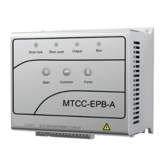
MTCC-EPB-A
MTCC-EPB-B
Advertisement

Related Manuals for hpmont MTCC-EPB-A


Summary of Contents for hpmont MTCC-EPB-A
- Page 1 MRL Electric Brake Release Device Instruction Manual Thank you for using the MTCC-EPB series electric brake release device developed by Shenzhen Hpmont Technology Co., Ltd. With the continuous development of modern elevator technology, energy-saving, environmental-friendly and space-saving permanent magnet synchronous elevators without machine room are more and more widely used.
- Page 2 Version and Revision Records Time: 2022/1 Version: V1.2 Revised Chapter Revised Contents Change the appearance of MTCC-EPB products •...
- Page 3 Characteristics • When MTCC-EPB series connects to door zone signal and elevator is in leveling area, it will stop outputting brake voltage and press the Force and Common buttons at the same time to continue output. • When MTCC-EPB series connects to door lock signal and door lock signal is disconnected, brake voltage output stops and the brake cannot be opened to ensure the passengers’...
-
Page 5: Mechanical Installation
1. Mechanical Installation MTCC-EPB series is installed in elevator control panel. 1. Planning installation space. The overall dimension is shown in the right figure, unit: mm. 2. Mark installation location on the wall and then drill (4-Φ5). The installation dimension is shown in the right figure, unit: mm. -
Page 6: Terminal Wiring
NC effective default, NO effective needs short signal NO/NC circuit of SEL and CME Brake voltage: Brake holding voltage: Brake power supply BK+, BK- DC110V (MTCC-EPB-A) DC80V (MTCC-EPB-A) output DC220V (MTCC-EPB-B) DC110V (MTCC-EPB-B) Terminal Wiring Wiring as shown below. •... - Page 7 MTCC-EPB series Brake Brake Leveling switch coil power supply Power +24V Door zone supply Output Power ground +24V +24V Switch power supply Car door lock Door lock circuit Door lock Hall door lock AC220V Relay for controlling electric brake release Note: KBR is located inside MTCC-EPB Photoelectric leveling switch wiring (High voltage, NC) MTCC-EPB series...
- Page 8 MTCC-EPB series Brake Brake Leveling switch coil power supply Power +24V Door zone supply Output Power ground +24V +24V Switch power supply Car door lock Door lock circuit Door lock Hall door lock AC220V Relay for controlling electric brake release Note: KBR is located inside MTCC-EPB Photoelectric leveling switch wiring (High voltage, NO) MTCC-EPB series...
- Page 9 3. Instructions 1. When the electric supply goes off, disconnect the Indicator power air-switch in control panel, please confirm Door Door that the door locks are closed and the elevator is lock zone Output Run not in the leveling area. 2.
-
Page 10: Troubleshooting
4. Troubleshooting Output Run Indicator Indicator Reason Method Reset (Green) (Green) Slow flashing Battery low Charge the battery • Auto-reset (lighting 1s, voltage Replace battery • lightless 1s) Check the brake coil to • make sure there is no Fast flashing short circuit DC output (lighting 25ms,... - Page 11 5. Technical Data Environment Installation Site Well ventilated inside control panel Running Temperature 0 - 40 ℃ Relative Humidity 5 - 95%, no water drops Storage Place Store in a dry, clean indoor place -20 - +55 ℃ , Max. 60 ℃ (no more than 24h) Storage Temperature Storage Time Total time of shipment and storage does not exceed 6 months...
Need help?
Do you have a question about the MTCC-EPB-A and is the answer not in the manual?
Questions and answers