Table of Contents
Advertisement
Quick Links
Advertisement
Table of Contents

Related Manuals for hpmont MTCC-V5


Summary of Contents for hpmont MTCC-V5
- Page 1 MTCC-V5/MTCC-V5-W Elevator Control Panel Starting Guide V1.1 2022.02...
-
Page 2: Table Of Contents
MTCC-V5-W .........................4 2. Mechanical Installation ..................5 2.1 Select Installation Environment ..............5 2.2 Install MTCC-V5 (Machine Room) ..............5 Determine the Installation Method ................5 Remove the Braking Resistor Box on the V5 Cabinet ...........5 Install the ARD to the V5 Cabinet (Optional) ..............5 Install the Braking Resistor Box to the ARD ..............6... - Page 3 4. Debugging ...................... 21 4.1 Operating Instruction .................. 21 Small Keypad Description ..................21 Inspection Operation ....................21 Emergency Stop Operation ..................21 Power-on Operation ....................21 4.2 Set Parameter .................... 21 4.3 Motor Parameter Auto-tuning ..............23 Asyn. Motor (Auto-tuning with Load) ................23 Asyn.
-
Page 4: Manual Instruction
Manual Instruction Using Objects This manual introduces the installation, wiring, debugging and fault information of MTCC-V5/MTCC-V5-W. Suitable for on-site installation of elevator control panels and elevator system debugging personnel. You should be trained or qualified to understand the basic principles of electricity, wiring, use of electrical components and tools. -
Page 5: Product Information
MTCC-V5 Machine room Control panel MTCC-V5-W Machine-roomless • MTCC-V5: Installed in the cabinet and completed wiring • MTCC-V5-W: Separately packaged, internal wiring has been Braking resistor box MTCC-BRB completed, and the wiring terminal is outside the wiring port, the wire length is 3m Including ARD wiring cable, ARD internal fixed braking resistor box... -
Page 6: Layout
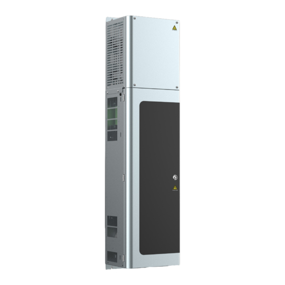
MTCC-V5/MTCC-V5-W Series Starting Guide V1.1 1.3 Layout MTCC-V5 Cabinet Door lock Nameplate Braking resistor Braking resistor box wiring port Control terminal, encoder cable wiring port Power cable, motor cable wiring port (top) [24] [25] [16] [10] [27] [26] [11] [17]... -
Page 7: Mtcc-V5-W
MTCC-V5/MTCC-V5-W Series Starting Guide V1.1 MTCC-V5-W ARD wiring port Door lock Nameplate Cabinet Control terminal, encoder cable wiring port Control terminal, (floor against the wall, wall- encoder cable wiring port mounted installation) (floor-standing, through-wall installation) Power cable, motor cable, brake resistor box wiring port (floor against the wall, wall-... -
Page 8: Mechanical Installation
MTCC-V5/MTCC-V5-W Series Starting Guide V1.1 2. Mechanical Installation 2.1 Select Installation Environment Installation Site Indoor, horizontal installation, well ventilated Ambient Temperature -10 - +40℃ , derating use at 40 - 50℃ Relative Humidity 5 - 95%, no condensation Atmospheric Pressure... -
Page 9: Install The Braking Resistor Box To The Ard
MTCC-V5/MTCC-V5-W Series Starting Guide V1.1 Install the Braking Resistor Box to the • Place the braking resistor box on top of the ARD, and put the cable through the connection port into the ARD; • Align the 4 mounting holes on the left and right;... -
Page 10: Other Combination Installation Methods
MTCC-V5/MTCC-V5-W Series Starting Guide V1.1 Other Combination Installation Methods Other combination installation methods can be selected according to the site conditions. • Install the V5 cabinet independently. • Install V5, braking resistor box and ARD independently. • Install V5 + braking resistor box in combination (default). - Page 11 MTCC-V5/MTCC-V5-W Series Starting Guide V1.1 Install ARD Independently See the table below for dimensions. 240mm 361mm 190mm Net Weight 17kg 4-Φd See the table below for installation dimension. 180mm 330.5mm 8.5mm Back size Install V5 + Braking Resistor Box in Combination (Default) 4-Φd...
-
Page 12: Install Mtcc-V5-W (Machine-Roomless)
MTCC-V5/MTCC-V5-W Series Starting Guide V1.1 2.3 Install MTCC-V5-W (Machine-roomless) According to site conditions, V5-W, braking resistor box and ARD are installed independently. V5-W can be installed in wall- mounted, floor-standing, and through-wall installations. See the table below for V5-W dimension. -
Page 13: Install V5-W Cabinet Independently (Through-Wall )
MTCC-V5/MTCC-V5-W Series Starting Guide V1.1 Install V5-W Cabinet Independently (Through-wall ) See the table below for surrounding space. A (Left and Right) ≥30mm B (Up and Down) ≥30mm Wall Install the Braking Resisitor Box Independently See the table below for dimensions. -
Page 14: Electrical Installation
MTCC-V5/MTCC-V5-W Series Starting Guide V1.1 3. Electrical Installation 3.1 Planning System Wiring System Complete Cables and Wiring Instructions Including power cables, machine room cables, travelling cables, shaft cables, car top cables, and pit cables. See the table below for descriptions and wiring locations. -
Page 15: Determine All Products Inlet And Outlet
MTCC-V5/MTCC-V5-W Series Starting Guide V1.1 The terminal description of the set of cables is shown below. Anti-reverse plugging function Plug Terminal • There is an identification on the plug head terminal, and each wire has a cable identification Terminal identification •... -
Page 16: Input Power Wiring (V5)
MTCC-V5/MTCC-V5-W Series Starting Guide V1.1 Input Power Wiring (V5) There are 5 cables, which is a system complete cables . It is a ring cable lug terminal, the specifications are shown in the table below. Terminal L1, L2, L3, N PE... -
Page 17: Motor Wiring (V5)
MTCC-V5/MTCC-V5-W Series Starting Guide V1.1 Motor Wiring (V5) There are 4 cables, which is the system complete cables. U, V, W are code end terminals, the specifications are shown in the table below. Tightening Torque (N·m) 1.2 - 1.5 Code End Teminal Max. -
Page 18: Interface Board Terminal Wiring (V5)
MTCC-V5/MTCC-V5-W Series Starting Guide V1.1 Interface Board Terminal Wiring (V5) Including machine room cables, travelling cables, and shaft cables, which is a system complete cables. Directly insert to the corresponding L1 L2 L3 N position according to the terminal identification, see section 3.1, page The terminal layout of interface board and definition is as following. - Page 19 MTCC-V5/MTCC-V5-W Series Starting Guide V1.1 AB: Travelling Cable Signal Definition Signal Definition SGC1/SGC2 Auxiliary door lock Down re-leveling 301A/302 24V power DC12 +12V power CAN+/CAN- CAN communication 12/13 Intercom signal Up re-leveling Door zone Safety circuit common BA: Shaft Safety Cable Signal Definition...
-
Page 20: Ard Wiring (V5) (Optional
MTCC-V5/MTCC-V5-W Series Starting Guide V1.1 ARD Wiring (V5) (Optional) ARD needs to be connected to KCB board J38, J12. The cable is in the ARD package. Remove the ARD Cover Tighten the screws Unscrew the screws • Unscrew the 4 screws counterclockwise;... -
Page 21: Mtcc-V5-W Wiring
MTCC-V5/MTCC-V5-W Series Starting Guide V1.1 3.3 MTCC-V5-W Wiring Grounding screws Machine room intercom Take the back wiring as an example. Remove V5-W Cabinet Door • Unscrew the ground screw counterclockwise (a). • Take out the key from the data plastic bag. -
Page 22: Motor Wiring (V5-W)
MTCC-V5/MTCC-V5-W Series Starting Guide V1.1 Motor Wiring (V5-W) There are 4 cables, which are the system complete cables. U, V, W are code end terminals, the specifications are shown in the table below. Tightening Torque (N·m) 1.2 - 1.5 Code End Teminal Max. -
Page 23: Ard Wiring (V5-W) (Optional)
MTCC-V5/MTCC-V5-W Series Starting Guide V1.1 ARD Wiring (V5-W) (Optional) ARD needs to be connected to KCB board J38, J12. The cable is in the ARD package. Remove the ARD Cover • Unscrew the 4 screws Unscrew the screws Tighten the screws counterclockwise;... -
Page 24: Debugging
MTCC-V5/MTCC-V5-W Series Starting Guide V1.1 4. Debugging STOP NORMAL 4.1 Operating Instruction Switch Small Keypad Description • 3 LED digital tubes. STOP NORMAL Display • 3 keys (PRG, UP, SET). Inspection Operation Small Turn the switch to EEO. • keypad Press and hold UP and RUN keys •... - Page 25 MTCC-V5/MTCC-V5-W Series Starting Guide V1.1 Encoder Parameters Ref. Code Function Recommended Setting Value Note F11.00 Encoder card selection F11.01 Encoder card pulses/rotation Based on the actual setting Setting by encoder Encoder card rotation F11.02 direction setting MCB Board, CTB Board Terminal Input and Output Parameters Ref.
-
Page 26: Motor Parameter Auto-Tuning
MTCC-V5/MTCC-V5-W Series Starting Guide V1.1 Ref. Code Function Recommended Setting Value Note CTB board X1 input terminal F13.01 101 (front door light curtain NC input) function CTB board X2 input terminal F13.02 106 (rear doorlight curtain NC input) function CTB board X3 input terminal 102 (front door open in place NC F13.03... -
Page 27: Syn. Motor (Auto-Tuning With Load)
MTCC-V5/MTCC-V5-W Series Starting Guide V1.1 Syn. Motor (Auto-tuning with Load) During auto-tuning with load, the motor needs to rotate. Confirm that the door lock circuit and the safety circuit are closed. Set F00.07 = 1 (distance control), F10.10 = 1 (auto-tuning with load). -
Page 28: Inspection Operation
MTCC-V5/MTCC-V5-W Series Starting Guide V1.1 4.4 Inspection Operation Confirm that the door lock circuit and the safety circuit are closed. According to the actual setting, set F03.06 (inspection Acc. speed), F04.00 (inspection run speed), and F26.12 (inspection parameter setting). Give the inspection and direction signals, and the elevator will run for inspection (or slow running). - Page 29 MTCC-V5/MTCC-V5-W Series Starting Guide V1.1 Note: In any of the following situations, shaft self-learning must be performed again: • Adjust the position of the leveling plate. • Adjust the position of the forced Dec. switch. • Modify F00.10 (elevator running direction).
-
Page 30: Inspection Before High Speed Operation
MTCC-V5/MTCC-V5-W Series Starting Guide V1.1 4.6 Inspection Before High Speed Operation Check System Communication The CAN+/CAN- of the interface board’s AB terminal are respectively connected to the CAN+/CAN- of the CTB board. The MOD+/MOD- of the interface board’s BB terminal are respectively connected to the MOD+/MOD- of the HCB board. -
Page 31: Debug Opening And Closing Door
MTCC-V5/MTCC-V5-W Series Starting Guide V1.1 Debug Opening and Closing Door The elevator is under inspection. Set the door controller parameters, ensuring that the door controller has a normal running curve and normally outputs opening and closing door in place signal. -
Page 32: Adjust Comfort Feeling
MTCC-V5/MTCC-V5-W Series Starting Guide V1.1 4.8 Adjust Comfort Feeling Adjust Starting Comfort Feeling Phenomenon and Adjustment Phenomenon When the elevator starts, the car has a sense of frustration (step sense). Adjustment Possible Reason Detection Method Treatment Measure Note Pre-torque isn't... -
Page 33: Adjust Running Curve
MTCC-V5/MTCC-V5-W Series Starting Guide V1.1 Adjust Running Curve Phenomenon and Adjustment Phenomenon The control panel adopts S-curve Acc. and Dec., which Min. the impact during Acc. and Dec., and makes the start and stop more stable. But di erent application occasions require di erent Acc. and Dec. curve parameters. -
Page 34: Adjust End Station Comfort Feeling
MTCC-V5/MTCC-V5-W Series Starting Guide V1.1 Adjust End Station Comfort Feeling Phenomenon and Adjustment Phenomenon The elevator runs to the forced reduction switch position, and the rapid change of speed moves to the leveling area at the crawling speed. Adjustment Possible Reason... -
Page 35: Adjust Leveling Accuracy
After the installation of the new elevator is completed, a running-in test shall be carried out on the new elevator . Set group F25 parameters to test the random running times of the elevator and the fixed running mode of the floor. 4.9 UCMP Application and Brake Force Test Application See "MTCC-V5 Elevator Control Cabinet Additional Instruction". -
Page 36: Car Top Inspection Communication Application
MTCC-V5/MTCC-V5-W Series Starting Guide V1.1 4.10 Car Top Inspection Communication Application V5/V5-W default car top wiring, F26.08 sets terminal function. When changing the wiring mode, set any group parameters from F13, H01, and F26.08 according to the actual wiring. Ref. Code... -
Page 37: Fan Lighting Application
MTCC-V5/MTCC-V5-W Series Starting Guide V1.1 4.11 Fan Lighting Application Confirm that the COB board communication is MTCC-COB-A successful and the elevator can be called; 2. Turn the DIP switch M1 of the COB board to the ON side, and the fan is illuminated. The input terminal is valid;... - Page 38 MTCC-V5/MTCC-V5-W Series Starting Guide V1.1 Description of Double Hall Calls on the Same Floor Connect the rear door HCB board to the Modbus bus; 2. Set the hall call address of the rear door = front door address + 24;...
-
Page 39: Manual Door Application
MTCC-V5/MTCC-V5-W Series Starting Guide V1.1 4.13 Manual Door Application Application Background When the car door and hall door used in the elevator are both manual doors, or the elevator only uses the hall door as the manual door (no car door). - Page 40 MTCC-V5/MTCC-V5-W Series Starting Guide V1.1 Proposed Ref. Code Function Setting Range Default Value 1 - 8s F12.38 000 = 1s Number of solenoid valve actions Bit10&Bit9&Bit8 …… 111 = 8s 0: Normal shutdown Semi-automatic manual door F12.38 Bit11 1: The hall door will not close until the...
-
Page 41: Power Failure Emergency Rescue Application (Optional)
MTCC-V5/MTCC-V5-W Series Starting Guide V1.1 4.14 Power Failure Emergency Rescue Application (Optional) MTCC-V5/V5-W is equipped with MTCC-ARD-V5 to realize the power failure emergency rescue function. Wiring MTCC-ARD-V5 externally connects three 12V/7AH lead-acid batteries in series which automatically outputs two voltages in case of power failure: •... - Page 42 MTCC-V5/MTCC-V5-W Series Starting Guide V1.1 Working State Description Power switch SW1 (button) LED3 (green) Slow flashing: On for 1s, o for 1s. LED1 (red) Fast flashing: On for 25ms, o for 25ms. LED2 (green) SW2 (DIP switch) Status Indication and Operating Instructions...
- Page 43 MTCC-V5/MTCC-V5-W Series Starting Guide V1.1 Fault Phenomenon LED1 LED2 LED3 Fault Troubleshooting and Reset (Red) (Green) (Green) Troubleshooting • No-load operation, confirm that there is no such fault • Turn o the power, measure the battery voltage with a E0002 multimeter, and confirm that the voltage is normal (10 - 12V)
-
Page 44: Machine-Roomless Electric Brake (Epb) Application
MTCC-V5/MTCC-V5-W Series Starting Guide V1.1 Fault Phenomenon LED1 LED2 LED3 Fault Troubleshooting and Reset (Red) (Green) (Green) Troubleshooting (reset the fault first, when the fault is not cleared) • Press SW1, restart ARD-V5, and confirm that the self-check is passed E0013 •... -
Page 45: Two Leveling Signals (Up And Down Leveling)
MTCC-V5/MTCC-V5-W Series Starting Guide V1.1 Two Leveling Signals (Up and Down Leveling) Signal Description Leveling Signal Location (Car Top Inspection Box) Definition Up leveling Pin3 of CTB-DZ (X9) Up leveling signal Down leveling Pin4 of CTB-DZ (X10) Down leveling signal... -
Page 46: Troubleshooting
MTCC-V5/MTCC-V5-W Series Starting Guide V1.1 5. Troubleshooting 5.1 Fault Phenomenon 【E41】 The control panel monitors various running Safety circuit disconnected conditions at all times. Once an abnormality occurs, the protection function will act, the keypad will Press PRG key to exit the fault display display fault information, and the running operation will be invalid. -
Page 47: Reset Fault
MTCC-V5/MTCC-V5-W Series Starting Guide V1.1 5.3 Reset Fault After the fault is removed, perform any of the following operations to reset: Keypad: Press STOP key. • • The control panel is completely powered down. • Some faults can be reset automatically, see the table below. - Page 48 Hpmont Group Company Shenzhen Hpmont Technology Co., Ltd. Add: Building 28, Wangjingkeng Industry Park, Xili Town, Nanshan District, Shenzhen, China Tel: +86 755-26791688 Fax: +86 755-26558128 Email: marketing@hpmont.com HPMONT (Hong Kong) Co., Ltd. Add: Room 709, 7/F, Silvercord Tower 1, 30 Canton Road, Tsim Sha Tsui, -Kowloon. Hong Kong Tel: +852 6607 2243 Email: info.hk@hpmont.com.hk...
Need help?
Do you have a question about the MTCC-V5 and is the answer not in the manual?
Questions and answers