Table of Contents
Advertisement
Quick Links
Advertisement
Table of Contents

Related Manuals for hpmont MTCC-E1


Summary of Contents for hpmont MTCC-E1
- Page 1 MTCC-E1 Escalator Control Panel Srarting Guide V1.1 2023.01...
- Page 2 Version and Revision Records Time: 2023/01 Version: V1.1 Chapter Content V1.1 version released...
-
Page 3: Table Of Contents
3.1 Plan System Wiring ......................7 3.1.1 System Complete Cables and Wiring Description..............7 3.1.2 System Complete Cables Terminal Description ............... 8 3.2 MTCC-E1 Wiring ........................9 3.2.1 Remove and Install Cover (Upper Panel) ................9 3.2.2 Open and Close Cover (Lower Panel) ..................9 3.2.3 Connect the Power Cable ...................... - Page 4 4.1.2 Description of Keypad and Indicator (Safty Board) ...............16 Indicator Description ......................16 Display State Description ......................16 4.1.3 Power-up Operation ......................17 4.1.4 EMG Stop Operation ......................17 4.1.5 Inspection (INS) Operation ....................17 4.2 Debugging Process ......................18 4.2.1 Set Parameters ........................18 Set Control Board Motor Parameters ..................18 Set Safety Board Parameters ....................18 4.2.2 Motor Auto-tuning .......................18 Asyn.
-
Page 5: Manual Instruction
Manual Instruction Using Objects This manual introduces the installation, wiring, debugging and fault information of MTCC-E1. Suitable for on-site installation of escalator control panels and elevator system debugging personnel. You should be trained or qualified to understand the basic principles of electricity, wiring, use of electrical components and tools. -
Page 6: Product Information
MTCC-E1 Starting Guide V1.1 1. Product Information 1.1 System Configuration Selection Product Model Description Include: Control panel MTCC-E1 • Upper panel: MTCC-E1-4TXXX-TP-O • Lower panel: MTCC-E1-BP-O Inspection handle box MT-IH-B Used when debugging Bluetooth module Onboard bluetooth module The delivery list include: •... -
Page 7: Layout
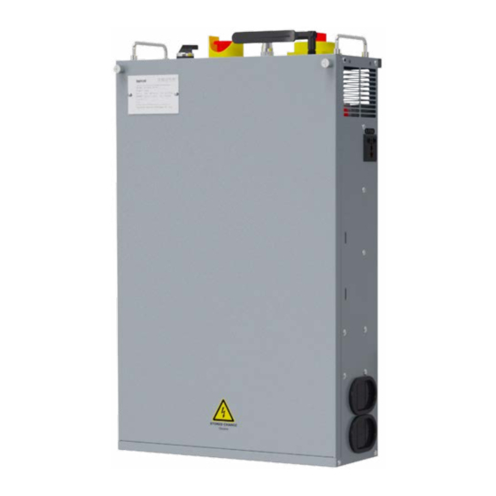
MTCC-E1 Starting Guide V1.1 1.3 Layout 1.3.1 Upper Panel Bottom Mounting hook Nameplate Power socket External structure Power cable wiring port Outlet Power and Signal cable (reserved) sealing plate signal cable wiring port (adjustable, wiring port (reserved) removable) Main power... -
Page 8: Lower Panel
MTCC-E1 Starting Guide V1.1 1.3.2 Lower Panel Bottom Power socket Outlet sealing plate (adjustable, External structure removable) Signal cable wiring port Handle Mounting hook INS outlet E-stop button Internal structure Cover Fault monitoring board 1.3.3 Inspection Handle Box STOP button... -
Page 9: Mechanical Installation
MTCC-E1 Starting Guide V1.1 2. Mechanical Installation 2.1 Select Installation Environment Installation Environment Indoor (no direct sunlight), vertical installation in the panel good ventilation Running Temperature -20 - +55℃ , 65℃ can be short-term full load operation Humidity 5 - 95%, no condensation... -
Page 10: Install The Lower Panel
MTCC-E1 Starting Guide V1.1 2.3 Install the Lower Panel For wall-mounted installation, see the steps below. 2.3.1 Plan the Installation Space Be vertical and upward. For installation space size see the table below. A (Left & Right) ≥50mm B (Up & Down) ≥100mm... -
Page 11: Electrical Installation
MTCC-E1 Starting Guide V1.1 3. Electrical Installation 3.1 Plan System Wiring 3.1.1 System Complete Cables and Wiring Description Includes power cables, upper panel cables, and lower panel cables. See the table below for descriptions and wiring locations. Cable Cable End Terminal... -
Page 12: System Complete Cables Terminal Description
MTCC-E1 Starting Guide V1.1 3.1.2 System Complete Cables Terminal Description See below for terminal descriptions of complete cables. Ring cable lug • When wiring, use screws to fix Cable mark Plug terminal • The plug terminals have terminal mark • Each wire has a cable mark •... -
Page 13: Mtcc-E1 Wiring
MTCC-E1 Starting Guide V1.1 3.2 MTCC-E1 Wiring 3.2.1 Remove and Install Cover (Upper Panel) Remove Cover • Remove the 2 captive screws counterclockwise (c.c.w.). • Lift the cover up to remove it. Install Cover After debugging, the cover can be installed. -
Page 14: Connect The Signal Cable (Upper Panel)
MTCC-E1 Starting Guide V1.1 3.2.4 Connect the Signal Cable (Upper Panel) The upper panel signal cables are the system complete cable. Plug directly into the corresponding position according to the terminal mark, see section 3.1, page 7. Uper panel Interface board... - Page 15 MTCC-E1 Starting Guide V1.1 JT1: Finger switch cable JT19: Upper chain breakage switch cable Signal Definition Signal Definition 119/120 Upper finger switch (right) 301/302 DC24V power 120/121 Upper finger switch (left) Upper chain breakage switch JT2: Skirt switch cable JT20: Handrail speed detect switch (left) cable Signal Definition...
-
Page 16: Connect The Signal Cable (Lower Panel)
MTCC-E1 Starting Guide V1.1 3.2.5 Connect the Signal Cable (Lower Panel) The lower panel signal cables are the system complete cable. Plug directly into the corresponding Lower panel position according to the terminal mark, see section 3.1, page 7. PE is ring cable lug, the Fault monitoring specifications see the table below. - Page 17 MTCC-E1 Starting Guide V1.1 JD1: Upper and lower panel connection cable JD9: Lower inspection cover cable Signal Definition Signal Definition Comb lighting L 301/302 DC24V power Lighting power N X12-1/ Lower inspection cover 2/1 X11-1 Comb lighting N Ground JD10: Lower entry photoelectric switch cable...
-
Page 18: Connect The Iot Module Cable
MTCC-E1 Starting Guide V1.1 3.2.6 Connect the IoT Module Cable Wire the MT70-CIC-ES or MT70-CIC-ESE depending on the installed IoT module. Connect MT70-CIC-ESEO (Optional) Antenna Hex nut Include MT70-CIC-EO board, antenna, RF cable, communication cable, hex nut. Rubber ring MT70-CIC-EO Connect the RF cable. -
Page 19: Debugging
MTCC-E1 Starting Guide V1.1 4. Debugging 显示 4.1 Operating Instruction 4.1.1 Description of Small Keypad and Indicator (Control Board) RUN ERR SAF INS Control board Status indicator Input and output indicator RUN ERR SAF INS LED diaplay • 3 LED digital tubes. -
Page 20: Description Of Keypad And Indicator (Safty Board)
DOWN SAVE Bit2 MTCC-E1 Starting Guide V1.1 Bit1 Bit0 4.1.2 Description of Keypad and Indicator (Safty Board) LED display POWER Bit3 DOWN SAVE Bit2 Bit1 Bit0 Safty board indicator Safty board indicator POWER • 3 LED digital tubes. • 3 buttons: SET (Exit), UP (Increase), DOWN (Decrease), SAVE (Confirm / enter the lower menu) . -
Page 21: Power-Up Operation
MTCC-E1 Starting Guide V1.1 4.1.3 Power-up Operation • Confirm that the wiring is correct. Turn the Main power switch to • ON (upper cabinet). Upper panel Main power switch (On, O ) 4.1.4 EMG Stop Operation Press any E-stop button (upper panel or lower panel), the escalator stops running. -
Page 22: Debugging Process
Set the safety board F00.13 (input terminal type) according to the actual X1 - X14 terminal type. • Check D01.08 (DI input status) to monitor the status of X1 - X14 signals. • If used with MTCC-E1, this step is not required. Set F00.09 according to the actual number of auxiliary brakes. -
Page 23: Debug Safety Board
MTCC-E1 Starting Guide V1.1 4.2.3 Debug Safety Board Confirm F00.20 = 1, enter debugging self-learning mode. Confirm the INS handle box is connected to the INS socket. Confirm the safety board Y00.00 = 8888, unlock the small keypad. Set the safety board F00.00 (system type) and F00.01 (nominal speed) according to the actual situation. -
Page 24: Variable-Frequency Running Process
MTCC-E1 Starting Guide V1.1 Variable-frequency Running Process Run command Close the variable frequency output contactor to run at variable frequency, open the brake Acc. to high-speed frequency There are three energy-saving modes when no one takes the escalator: • Low-speed energy-saving running High-speed running (F02.00 = 0). -
Page 25: Use Ota To Upgrade Software
MTCC-E1 Starting Guide V1.1 4.3 Use OTA to Upgrade Software Use HP-OTA-A by PC or Android phone, remotely upgrade the software of MTCC-E1. • The computer client is a compressed package, the Android phone is an apk program. The control board (upper panel) contains two chips, and the software needs to be upgraded separately. -
Page 26: Troubleshooting
MTCC-E1 Starting Guide V1.1 5. Troubleshooting 5.1 Fault Phenomenon The control panel monitors each operating condition at all times. If a fault occurs, the protection function acts, the upper panel displays the fault. Meanwhile, faulty relay acts, the running operation is invalid, the motor coasts to stop. - Page 27 • Output voltage phase • Check the wiring between disconnection or loss MTCC-E1 and motor Output voltage phase • Three phase load of MTCC-E1 • Check the motor loss is severely unbalanced • Acc. time is too short • Adjust Acc. time Controller overload •...
- Page 28 MTCC-E1 Starting Guide V1.1 Fault Code Fault Sub-code Fault Reasons Counter-measures • Motor speed measuring • Check the motor speed equipment fault measuring equipment Motor speed measuring fault • Motor speed protection • Check the wiring of motor parameter setting error speed measuring equipment •...
-
Page 29: Safety Board Fault
MTCC-E1 Starting Guide V1.1 5.2.2 Safety Board Fault The system has a saftey board fault, see the table below for troubleshooting, and display the fault: • Safety board display: Small keypad display EXX (fault code) + XX (fault sub-code), Err indicator is always Diaplay fault •... - Page 30 MTCC-E1 Starting Guide V1.1 Fault Code Fault Sub-code Fault Reasons Counter-measures 00: Abnormal power signal • Faulty safety board • Check or replace the safety board Self-check signal 01: Disconnect the Y1/Y2 relay, • When the Y1/Y2 relay is abnormal...
- Page 31 MTCC-E1 Starting Guide V1.1 Fault Code Fault Sub-code Fault Reasons Counter-measures 01: Main and auxiliary model • Model series error • Manually reset the series error fault, power up again Abnormal main and after power down. auxiliary comparison, 02: Main and auxiliary hardware •...
-
Page 32: Safety Function Measures
MTCC-E1 Starting Guide V1.1 5.2.3 Safety Function Measures Switch O Switch O Must be Safety Function Description the Power Supply to the Safety Circuit Reset Manually the Auxiliary Brake Check speed, take e ect until speed > 1.2 times nominal speed Check speed, take e ect until speed >... -
Page 33: Parameters Table
MTCC-E1 Starting Guide V1.1 6. Parameters Table 6.1 Control Board Parameters 6.1.1 Group D: Display Parameters Use the external LED keypad to check parameters. Bit15 Bit13 Bit11 Bit9 Bit14 Bit12 Bit10 Bit8 D01.06 - D01.16 need to check the status of LED digital tube. - Page 34 MTCC-E1 Starting Guide V1.1 Ref. Code Function Setting Range Default Bit0: Safety switch Bit1: Inspection Bit2: Up Bit3: Down Bit4: Motor speed test Bit5: Adhesion Bit6: Break Bit7: Brake Bit8: Reverse D01.10 Control board input logic state 1 Bit9: Upper photoelectric...
- Page 35 MTCC-E1 Starting Guide V1.1 Ref. Code Function Setting Range Default Bit0: Bypass contactor Z10 control Bit1: Up bypass contactor Z11 control Bit2: Down bypass contactor Z12 control Bit3: Run contactor Bit4: Brake contactor Bit5: Refueling output Bit6: Buzzer output Bit7: Auxiliary brake contactor Bit8: Star contactor drive D01.14...
-
Page 36: Group F: General Function Parameters
MTCC-E1 Starting Guide V1.1 6.1.2 Group F: General Function Parameters Ref. Code Function Setting Range Default F00: Basic Parameters 0: Keypad running 1: Bypass variable frequency F00.00 Escalator running mode 2: All-variable frequency running 3: Star-delta start 0: V/f control F00.01... - Page 37 MTCC-E1 Starting Guide V1.1 Ref. Code Function Setting Range Default 0: After the three phase input is powered o , not detect the safety switch signal F03.09 Power-o detect safety switch 1: After the three phase input is powered o ,...
- Page 38 MTCC-E1 Starting Guide V1.1 Ref. Code Function Setting Range Default F05: Control Board Input Function Parameters F05.00 Terminal detection filter time 0 - 100ms 10ms Note: No. 5, 12 - 15 functions only support F05.12 F05.01 Terminal X1 function - F05.17 (DI1 - DI6) settings F05.02...
- Page 39 MTCC-E1 Starting Guide V1.1 Ref. Code Function Setting Range Default F07: Interface Board Digital Output Parameters 0: Unused 1: Run contactor F07.01 Y1 relay output 2: Grid up contactor 3: Grid down contactor 4: Star contactor 5: Delta contactor 6: Brake contactor F07.02...
- Page 40 MTCC-E1 Starting Guide V1.1 Ref. Code Function Setting Range Default F09: V/f Control Parameters 0: Straight line V/f curve 1: Square Curve F09.00 V/f curve 2: 1.2th power curve 3: 1.7th power curve 4: User-defined curve F09.01 V/f frequency F3 F09.03 - F08.03...
- Page 41 MTCC-E1 Starting Guide V1.1 Ref. Code Function Setting Range Default F12.10 Subnet mask 0 0 - 255 F12.11 Subnet mask 1 0 - 255 F12.12 Subnet mask 2 0 - 255 F12.13 Subnet mask 3 0 - 255 F12.14 Gateway 0 0 - 255 F12.15...
- Page 42 MTCC-E1 Starting Guide V1.1 Ref. Code Function Setting Range Default 0: Disable 1: Enable F14.23 Keypad forward and reverse key Note: Only valid when F00.00 = 0 (keypad running) F15: Fault Record Parameters F15.00 No. 1 fault type F15.01 No. 2 fault type F15.02...
-
Page 43: Safety Board Function Parameters
MTCC-E1 Starting Guide V1.1 6.2 Safety Board Function Parameters 6.2.1 Group D: Display Parameters Ref. Code Function Setting Range Default D00: System Status Display Parameters D00.00 Product Series D00.01 Hardware version D00.02 Software version D00.03 Software non-standard version Actual value D00.04... - Page 44 MTCC-E1 Starting Guide V1.1 Ref. Code Function Setting Range Default D01.20 Signal A pulses between upper steps D01.21 Signal B pulses between upper steps D01.22 Signal A pulses between lower steps D01.23 Signal B pulses between lower steps D01.24 Power signal 1 D01.25...
- Page 45 MTCC-E1 Starting Guide V1.1 Ref. Code Function Setting Range Default Unit: Y2 safety relay feedback signal Ten: Y4 safety relay feedback signal Hundred: Y6 safety relay feedback signal D02.09 Relay status Thousand: Y2 safety relay output signal Ten thousand: Y4 safety relay output signal •...
-
Page 46: Group F: General Function Parameters
MTCC-E1 Starting Guide V1.1 6.2.2 Group F: General Function Parameters Ref. Code Function Setting Range Default F00: Setting Parameters 0: Escalator 1: Passenger conveyors 1 (step tread size F00.00 System type 13.3cm) 2: Passenger conveyors 2 (step tread size 26.6cm) •... - Page 47 MTCC-E1 Starting Guide V1.1 Ref. Code Function Setting Range Default 0: Unused 1: Inspection (INS) signal 2: INS up 3: INS down 4: Running signal 5: Working brake feedback 1 6: Working brake feedback 2 F00.24 X1 terminal function 7: Auxiliary brake feedback 1...
- Page 48 MTCC-E1 Starting Guide V1.1 Ref. Code Function Setting Range Default F02: Vice Chip Record Parameters F02.00 No. 1 fault type F02.01 No. 2 fault type F02.02 No. 3 fault type F02.03 No. 4 fault type F02.04 No. 5 fault type F02.05...
- Page 49 Hpmont Group Company Shenzhen Hpmont Technology Co., Ltd. Add: Building 28, Wangjingkeng Industry Park, Xili Town, Nanshan District, Shenzhen, China Tel: +86 755-26791688 Fax: +86 755-26558128 Email: marketing@hpmont.com HPMONT (Hong Kong) Co., Ltd. Add: Room 709, 7/F, Silvercord Tower 1, 30 Canton Road, Tsim Sha Tsui, -Kowloon. Hong Kong Tel: +852 6607 2243 Email: info.hk@hpmont.com.hk...
Need help?
Do you have a question about the MTCC-E1 and is the answer not in the manual?
Questions and answers