Advertisement
Available languages
Available languages
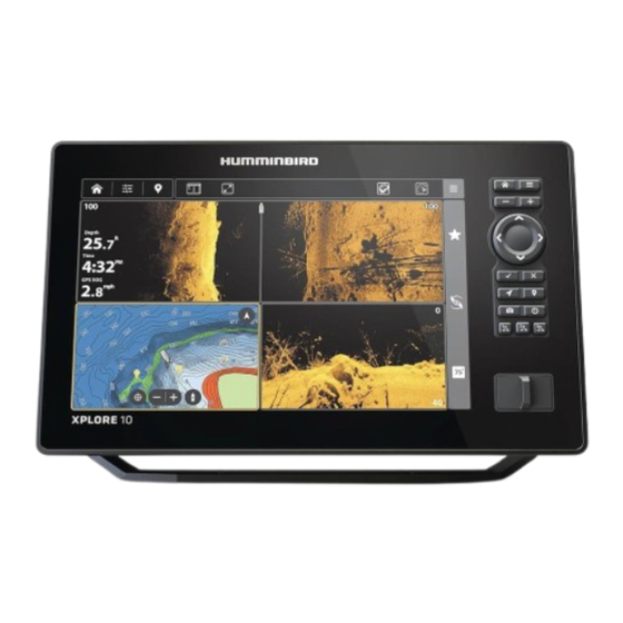
XPLORE™ SERIES IN-DASH MOUNTING Installation Guide
Overview
Following are instructions for the in-dash mount installation of the XPLORE control head. We
encourage you to read this guide before starting the installation, so you may understand the
installation requirements.
Technical Support: If you find that any items are missing from your installation kit, contact Humminbird®
Technical Support through our Help Center at https://humminbird-help.johnsonoutdoors.com/hc/en-us.
Supplies: In addition to the hardware supplied with your accessory, you will need a drill and various
drill bits, a cutting tool for the dashboard material, 7/16" (11 mm) adjustable wrench, safety glasses
and dust mask, and masking tape. If the dashboard is thicker than 5/8" (16 mm), you may need to use
the longer carriage bolts (included with hardware). Optionally, for single control head installations,
you may choose to use the (2) gimbal knobs included with your control head.
Do NOT use power tools to secure the hardware. We encourage you to read the installation
instructions so you may understand the installation requirements.
The illustrations in this manual may not look the same as your product, but your product
will function in the same way.
1
| Plan the Mounting Location
Start by locating a suitable, flat area of the dashboard for mounting. Consider the following to find
the best mounting location:
Δ Interference: The mounting location must provide adequate distance from electric motors or
any equipment that may cause electronic interference.
Δ Stability: The mounting area should be protected from waves, shock, vibration, and water.
Δ Depth: The mounting area should have the following depths to allow space for the control head
and cables.
XPLORE 9: 4.8" (121.9 mm) minimum
XPLORE 10: 5.3" (134.6 mm) minimum
XPLORE 12: 5.3" (134.6 mm) minimum
Δ Ventilation: The area beneath the mounting surface should be well ventilated.
Δ Accessibility: The location should be easily accessible for all cables to reach the ports on the
back of the control head.
Δ Multiple Control Heads: If you plan to install more than one control head side by side, leave a
minimum space of 1" (25.4 mm) horizontally or vertically between control heads. Take your
measurement from the front edges of the control head. See the template for more information.
If a cable is too short for your application, extension cables are available. For assistance,
contact Humminbird Technical Support.
2
| Cut the In-Dash Mounting Hole
To in-dash mount the XPLORE control head, start by placing the components on the surfaces where
you intend to install them.
1. Review the instructions, measurements, and cutting options indicated on the In-dash Mounting
Template.
2. Tape the template to the chosen in-dash mounting location.
CAUTION
NOTE
NOTE
1
532990-1_A
Advertisement
Table of Contents

Related Manuals for Humminbird XPLORE Series


Summary of Contents for Humminbird XPLORE Series
- Page 1 Technical Support: If you find that any items are missing from your installation kit, contact Humminbird® Technical Support through our Help Center at https://humminbird-help.johnsonoutdoors.com/hc/en-us.
-
Page 2: Install The Bracket
XPLORE™ SERIES IN-DASH MOUNTING Installation Guide 532990-1_A 3. Using the template, select the cutting method that is best for your boat: Δ Drill one entry hole away from the main cut line that is large enough to insert the blade of your cutting tool. - Page 3 XPLORE™ SERIES IN-DASH MOUNTING Installation Guide 532990-1_A Installing the Bracket (Screws) seal washer flat washer screw opening in bracket arms facing forward Install the gimbal knobs into each side of the control head with the flat washer (.235" x 1.4") and seal washer (1/4 x 1 1/4) in the order shown in the illustration Installing the Bracket (Gimbal Knobs).
- Page 4 Cover any unused ports with the tethered caps to prevent potential damage. Your control head is ready for operation. See the Quick Start Guide to get started and download screw nut the XPLORE Operations Manual from our Web site at humminbird.johnsonoutdoors.com.
-
Page 5: Year Limited Warranty
This does not include shipping replaced free of charge at Humminbird’s option and returned to the time to and from our factory. Units received on Friday are typically customer freight prepaid. -
Page 6: Returning Your Unit For Service
XPLORE™ SERIES IN-DASH MOUNTING Installation Guide 532990-1_A Returning Your Unit for Service Contact Humminbird Before sending your unit in for repair, please contact Humminbird Contact Humminbird Technical Support through our Help Center at Technical Support through our Help Center at https:// https://humminbird-help.johnsonoutdoors.com/hc/en-us or by humminbirdhelp. -
Page 7: Présentation De L'installation
Assistance technique : Si vous découvrez que des articles sont manquants dans votre trousse d’installation, contactez le support technique Humminbird via notre centre d’aide à l’adresse https:// humminbird-help. johnsonoutdoors.com/hc/en-us. Matériel : En plus de la quincaillerie fournie avec votre accessoire, vous aurez besoin d’une perceuse et de différents forets, d’un outil de coupe pour le matériau du tableau de bord, d’une clé... - Page 8 DU MONTAGE DE TABLEAU DE BORD DE LA SÉRIE XPLORE 532990-1_A 1. Consultez les instructions, les mesures et les options de découpage indiquées sur le Gabarit de montage du tableau de bord. 2. Collez le gabarit sur l’emplacement de montage du tableau de bord choisi à l’aide d’un ruban adhésif. 3.
- Page 9 DU MONTAGE DE TABLEAU DE BORD DE LA SÉRIE XPLORE 532990-1_A Pour les têtes de commande qui seront installées côte à côte, installez les vis (1/4 po - 20) dans les bras de support avec la rondelle plate (0,235 po x 1,4 po) et la rondelle d’étanchéité (1/4 po x 1 1/4 po) dans l’ordre indiqué...
-
Page 10: Branchement Des Câbles
DU MONTAGE DE TABLEAU DE BORD DE LA SÉRIE XPLORE 532990-1_A REMARQUE Si la tête de commande n’est pas correctement insérée dans le trou de montage, retirez l’une des molettes à cadran et positionnez la tête de commande dans le trou de montage. Remplacez la molette à... - Page 11 Cette garantie est en vigueur pour une durée de deux ans appareils réparés en usine sont testés de la même façon et subissent à partir de la date de l’achat initial. Les produits de Humminbird qui les mêmes contrôles de qualité que les nouvelles unités en production.
- Page 12 DIRECTIVE DEEE : La directive EU 2002/96/CE sur les « déchets d’achat). d’équipements électriques et électroniques (DEEE) » concerne la plupart Δ Renvoyer le produit, fret payé à l’avance, à Humminbird. Assurer des distributeurs, vendeurs et fabricants d’équipements électroniques l’expédition et demander une preuve de livraison.
Need help?
Do you have a question about the XPLORE Series and is the answer not in the manual?
Questions and answers