Table of Contents
Advertisement
Advertisement
Table of Contents

Related Manuals for Humminbird 300TX


Summary of Contents for Humminbird 300TX
-
Page 2: Installation Preparation
All Humminbird accessories are available through your full- service Humminbird dealer or factory direct through our number listed in the Customer Support section. INSTALLATION OVERVIEW Your Humminbird fishfinder consists of two primary components to install: the control head and the transducer. - Page 3 INSTALLATION PREPARATION Determining How to Mount the Transducer Your Humminbird fishfinder includes a standard transducer. This transducer can be mounted on the transom of the boat or bonded to the inside of a fiberglass hull boat. The transom installation, which is the most widely used, places the transducer on the outside of the boat hull.
- Page 4 ALTERNATE MOUNTING METHODS ALTERNATE TRANSDUCERS AND MOUNTING METHODS Your Humminbird fishfinder comes with everything necessary for installation and operation on most boats. However, there are several situations which may require a different type of transducer. Inboard boats, wood or metal hulls, and sail boats create unique transducer mounting needs Alternate transducers and mounting methods are detailed below.
- Page 5 BEGINNING INSTALLATION Now that you have determined the transducer mounting method you can begin installation of your new Humminbird fishfinder. The installation guide included on the next few pages provides detailed step by step instructions for installation of the control head and transducer.
- Page 6 Do not begin this transducer installation until you read the Installation Preparation in the Operation Guide. This chapter contains information critical to the correct installation of your transducer. Due to the wide variety of boat hulls, only general instructions are presented in the installation guide.
- Page 7 If the propeller(s) is (are) forward of the transom, it may be impossible to find an area clear from turbulence, and a different mounting technique or transducer type should be considered. Step Two - Drill the Mounting Holes 1. Remove the mounting template from the front of the Operations Manual. 2.
- Page 8 Step Four - Mount the Transducer to the Transom 1. Apply silicone sealant to the mounting holes drilled into the transom. 2. Align the transducer assembly with the drilled holes in the transom (Figure 8). 3. Use either a flat head screwdriver, a 5/16" (8mm) hex driver, or a 5/16" (8mm) socket to mount the assembly.
- Page 9 If the cable is too short, extension cables are available to extend the transducer cable up to a total of 50' (15 m). Call Humminbird Customer Support for more information. Follow these steps to route the cable through the transom: 1.
- Page 10 Inside the hull mounting generally produces good results in single thickness fiberglass-hulled boats. Humminbird cannot guarantee depth performance when transmitting and receiving through the hull of the boat since some signal loss occurs. The amount of loss depends on hull construction and thickness, and the installation.
- Page 11 3. Power up the Control Head. 4. Run the boat at various speeds and water depths while observing the screen on the Control Head. If the unit functions well at low speeds but begins to skip or miss the bottom at higher speeds, the transducer needs to be moved. If depth performance is required, test the fishfinder in water at the desired depth.
- Page 12 CONTROL HEAD INSTALLATION Step One - Determine Where to Mount Begin the installation by determining where to mount the control head. Consider the following to determine best location: The cables for power, transducer and temp/speed accessories (if applicable) should be installed first and must reach the mounting location. Extension cables are available.
- Page 13 (not included) for the protection of the unit (Figure 21). Humminbird is not responsible for over voltage or over current failures. In order to minimize the potential for interference with other marine electronics a separate power source (such as a second battery) may be necessary.
- Page 14 5. Install the control head by sliding it onto the mounting bracket until it is fully seated. To remove the unit simply depress the latch on the rear of the unit and lift (Figure 29). Your Humminbird is now ready for operation. INSTALLATION CONTROL HEAD INSTALLATION...
- Page 15 Note: it is often necessary to make several incremental transducer adjustments before optimum high-speed performance is achieved. Important: For Transom Mount transducer installations, install the third mounting screw after the final transducer adjustments. Humminbird 3 Humminbird Lane Eufaula, Alabama 36027...
- Page 16 When the screen times out, the unit will be in simulator mode. When in simulator operation, the 300TX responds to control inputs as if it is in actual operation, so feel free to experiment, or to customize the unit for your particular operation.
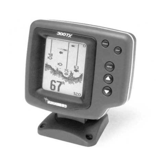
- Page 17 What You See On-Screen Your 300TX uses a 128 x 64 matrix FSTN LCD display. This display provides outstanding viewability in all light conditions over a wide range of temperatures. At initial power-up, the 300TX uses settings that were set in the factory.
- Page 18 The best way to learn to interpret structure is to operate the 300TX over a variety of known conditions and experiment with user functions to best represent those conditions on-screen.
- Page 19 The backlight is very effective for low-light and nighttime operation. When the backlight is on, the 300TX will consume more power than the backlight off. This is important when using the 300TX in a portable configuration powered by a separate battery, or when powering the unit from a trolling motor battery.
- Page 20 Sensitivity. The sensitivity function controls the sensitivity of the sonar receiver. The 300TX automatically adjusts the level of receiver sensitivity based on a number of factors including the depth of the water and the level of noise present. Noise can be caused by other electronic devises, engines, trolling motors, propeller cavitation and hydrodynamic flow among others.
- Page 21 The 300TX automatically adjusts the depth range depending on the depth of the water. The unit tries to maintain the bottom depiction about 2/3 down the total range (for example, in 20’...
- Page 22 When the unit is powered off, the Zoom menu returns to Zoom Off. Depth Alarm. The 300TX contains an audible alarm to warn you of shallow water depths. The alarm is adjustable to depths of 2’ (.6m) to 99’ (30m). When the alarm is enabled, an audible alarm sounds if the water beneath the boat is equal to or less than the selected alarm depth.
- Page 23 The 300TX will operate at voltages from 10 to 20 VDC. Voltages in excess of 20 or less than 10 VDC cause the unit to power off.
- Page 24 “Side” for the WideSide transducer. Often a transducer switch is used to connect two tri-beams transducers, or a tri-beam and a wide side to the 300TX. In “Auto” the 300TX identifies the transducer as the...
- Page 25 Selecting Show brings up the Diagnostic screen. See the Using Diagnostic section for more information. Reset. With the many User Options available to customize the 300TX, it is easy to configure the unit in such a way that it is detrimental to a particular use. By using the Reset function, all variable or user-controlled features of the 300TX are returned to the factory settings.
- Page 26 Diagnostic can also be accessed through the Options menu. Self Test. Initially, the 300TX will perform a self-test. This test confirms the operation of all internal circuitry. At the conclusion of the test, one of two messages will appear.
- Page 27 The Wide Side transducer can be connected directly to the 300TX or used in conjunction with the standard transducer through a transducer switch. When used with a switch in conjunction with the Tri-Beam transducer, the 300TX recognizes which transducer is connected whenever the switch position is changed.
- Page 28 Maintenance Your 300TX is designed to provide years of trouble free operation with virtually no maintenance. Follow these simple procedures to ensure your 300TX continues to deliver top performance. If the unit comes into contact with salt spray, simply wipe the affected surfaces with a cloth dampened in fresh water.
Need help?
Do you have a question about the 300TX and is the answer not in the manual?
Questions and answers