Advertisement
Quick Links
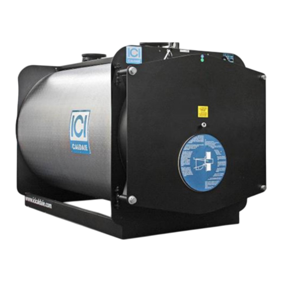
LOW NOx PRESSURISED STEEL BOILERS
GREENOx .e
WITH THREE GAS PASSES
GREENOx .BT COND
LOW RETURN TEMPERATURE WITH CONDENSER
INSTALLATION, USE AND MAINTENANCE MANUAL
Cooke Industries - Phone: +64 9 579 2185 Email: sales@cookeindustries.co.nz Web: www.cookeindustries.co.nz
EN
GREENOx_en_02 07_2024 - 07/2024
Advertisement

Related Manuals for ICI Caldaie GREENOx .e


Summary of Contents for ICI Caldaie GREENOx .e
- Page 1 LOW NOx PRESSURISED STEEL BOILERS GREENOx .e WITH THREE GAS PASSES GREENOx .BT COND LOW RETURN TEMPERATURE WITH CONDENSER INSTALLATION, USE AND MAINTENANCE MANUAL GREENOx_en_02 07_2024 - 07/2024 Cooke Industries - Phone: +64 9 579 2185 Email: sales@cookeindustries.co.nz Web: www.cookeindustries.co.nz...
- Page 2 INDEX INTRODUCTION SAFETY WARNINGS GENERAL WARNINGS TECHNICAL SPECIFICATIONS GREENOX BT COND BOILER INSTALLATION THERMAL PLANT HYDRAULIC CONNECTION ELECTRICAL CONNECTION OPTIONAL CONTROL PANEL INSTALLATION OF GREENOX.E 80 ÷ 300 BOILER CONTROL PANEL DOOR BURNER CONNECTION ASSEMBLY BOILER CASINGS AND CONTROL PANEL START UP PRELIMINARY CHECKS WATER TREATMENT...
- Page 3 INTRODUCTION Dear Customer, Thank you for having chosen our generator. In your interests, we invite you to follow and observe the instructions in this manual to ensure the highest level of efficiency and duration of the unit. IMPORTANT failure to observe the instructions in this manual will void the warranty conditions. INTRODUCTION Cooke Industries - Phone: +64 9 579 2185 Email: sales@cookeindustries.co.nz Web: www.cookeindustries.co.nz...
- Page 4 SAFETY WARNINGS IMPORTANT – For safety and for proper operation, carefully read this TECHNICAL MANUAL before installing and starting the generator. The manual is an integral and essential part of the generator and must accompany it from installation until disposal. The generator must be used for the purpose for which it was strictly intended and any liability by the Manufacturer for damages to people, animals or property due to lack of maintenance or for improper use, is excluded.
- Page 5 GENERAL FEATURES This steel boiler range features 3 gas passes with no flame inversion. This design minimises the formation of nitrous oxides (NOx) caused by the high temperatures and long flame stay times typical of traditional boiler furnaces. Furthermore, the BT range boilers have been designed for low temperature operations (return at 35°C). For this reason, a double tube and a special smokebox refractory protection are essential to maintain the high temperature of parts in contact with combustion product, and without condensate production.
- Page 6 GENERAL WARNINGS Each generator is provided with a manufacture plate that can be found in the envelope with the boiler documents. The plate lists: – Serial number or identification code; – Rated thermal output in kcal/h and in kW; – Furnace thermal output in kcal/h and in kW; –...
- Page 7 TECHNICAL SPECIFICATIONS GREENOX.E 10 ÷ 70 BOILER GREENOx.e DESCRIPTION u.m. Temp. media Heat output 70°C Heat input Medium Efficiency 100% (N.C.V.) 95,24 95,33 95,24 95,37 temp. 70°C NG max flow rate G20 46,67 52,17 66,67 77,67 NG max flow rate G30 kg/h 34,64 38,72...
- Page 8 Flow Return Fitting for instruments System filling/drainage Fitting for safety valves Bulb wells Boiler condensation drain Inspection well One fitting only GREENOX.e DESCRIPTION u.m. 1210 1340 1422 1475 1605 1725 1555 1685 1802 1913 2191 2193 1462 1744 1746 1075 1100 200 - 250 Ǿb...
- Page 9 CALDAIA GREENOX.E 80 ÷ 300 GREENOx.e DESCRIPTION u.m. Temp. media Heat output 1000 1200 1400 1700 2000 2300 70°C Heat input 1050 1259 1469 1784 2099 2415 Medium Efficiency 100% (N.C.V.) 95,35 95,34 95,24 95,31 95,30 95,29 95,28 95,24 temp. 70°C NG max flow rate G20 88,78 99,89...
- Page 10 GREENOX.e DESCRIPTION u.m. Heat output 2600 3000 Temp. media 70°C Heat input 2731 3150 Medium Efficiency 100% (N.C.V.) 92,20 95,24 temp. 70°C NG max flow rate G20 288,99 333,33 NG max flow rate G30 kg/h 241,49 247,40 NG max flow rate G31 kg/h 212,16 244,72...
- Page 11 Flow Return Fitting for instruments System filling/drainage Fitting for safety valves Bulb wells Boiler condensation drain Inspection well INTRODUCTION Cooke Industries - Phone: +64 9 579 2185 Email: sales@cookeindustries.co.nz Web: www.cookeindustries.co.nz...
- Page 12 GREENOX.e DESCRIPTION u.m. 1712 1764 2065 1600 1650 1950 1040 1380 1490 1800 1180 1290 1600 2535 2589 2899 2966 3466 3935 1970 1972 2282 2324 2824 3324 1300 1550 1500 2000 2500 300-350 360-410 Ǿb Ǿc DN/in DN/in N1/N2 DN/in 1”...
- Page 13 GREENOX BT COND BOILER Boiler flow Condenser return temperature control Boiler return Condenser flow Fitting for instruments Condenser return Boiler drain Condenser condensation drain Fitting for safety valves Condenser drain Bulbs wells Air vent fitting Inspection well Condenser flow temperature control GREENOX BT COND DESCRIPTION u.m.
- Page 14 GREENOX BT COND DESCRIPTION u.m. 2089 2121 2448 2554 1950 2064 1040 1490 1800 1600 3330 3797 4180 4680 1474 1941 2824 3324 2000 2500 1330 1300 360-410 Ǿb Ǿc DN/in DN/in N1/N2 1”1/4 DN/in 1/2” DN/in DN/in 1/2” DN/in/mm DN/in 1”...
- Page 15 INSTALLATION Before connecting the boiler, perform the following operations: – Thoroughly clean all the system pipes in order to remove any foreign matter that could affect correct operation of the boiler; – Check that the flue has an adequate draught, that there is no narrowing of passages and that it is free from debris; also check that other appliances do not discharge into the flue (unless designed to serve several utilities).
- Page 16 HYDRAULIC CONNECTION SEALED Hot water heating system with expansion vessel N1 Flow The generator must be provided with: a1 safety valve N2 Return a2 safety valves if output is (≥ 500.000 kcal/h) N3 Instrument fitting b Expansion vessel N4 Lower fitting: c Regulation thermostats N4b expansion vessel fitting d 1st safety thermostat...
- Page 17 ELECTRICAL CONNECTION Electrical systems of thermal plants designed only for heating purposes must comply with numerous legal regulations which apply in general as well as specifically to each application or fuel type. OPTIONAL CONTROL PANEL The control panel (optional) with the boilers is made of IP40 protection plastic material, and houses the regulation and safety instruments: NET WARNING LIGHT BURNER SWITCH...
- Page 18 INSTALLATION OF GREENOX.E 80 ÷ 300 BOILER CONTROL PANEL IMPORTANT The control panel picture is purely indicative as it may vary according to the type of panel installed. Choose the side on which to install the control panel (RH or LH), remove the covers (1) and push in the pre-cut opening (2). Pick up the kit of the arm complete with bracket (3).
- Page 19 The bracket provided, which is equipped with a 2-hole shaped plate, enables the user to mount the panels with two inclinations, and hence to choose the position he/she prefers (see figures). INSTALLATION Cooke Industries - Phone: +64 9 579 2185 Email: sales@cookeindustries.co.nz Web: www.cookeindustries.co.nz...
- Page 20 DOOR DOOR OPENING The door is adjusted in the factory with standard opening to the left (s) and with hinges on the right (d). DANGER it is dangerous to unscrew the ring nuts (8d) on the side of the hinges to avoid causing the door to detach, with possible serious damage to people and property.
- Page 21 DOOR ADJUSTMENT (OPENING ON THE RIGHT) Vertical adjustment 1. With the door ajar, loosen the counter-nuts (5s) of the hinge units. 2. Act on the adjustment nuts (4s) to lift or lower the door by centring the gasket on the stop plate (see figure), then block the counter-nuts (5s).
- Page 22 BURNER CONNECTION Before installation you are advised to thoroughly clean the inside of all the fuel supply system pipes in order to remove any foreign matter that could affect correct operation of the boiler. See technical specification tables and check the max pressure value inside the furnace.
- Page 23 ASSEMBLY IMPORTANT Valid up to GREENOX.e 70 BOILER CASINGS AND CONTROL PANEL 1) Wrap the fibreglass around the boiler body and use the supplied strap to secure it (see fig.). DIAGRAM OF PLASTIC STRAP LOCKING TO SECURE THE FIBREGLASS TO THE BOILER SHELL 2) Prepare the staves by inserting the four stoppers, as shown in the figure.
- Page 24 3) Fasten the uprights and the beams to the plates by means of appropriate screws and nuts. NOTE: the beam shown in the figure, if supplied in the package, must be placed between the two tube panels in order to support the staves.
- Page 25 4) Insert the staves, with the previously installed stoppers, between the uprights and the beams, as shown in the figure. PLEASE NOTE: do not cover the upper corner on the manhole side; this is required for the subsequent installation of the control panel and its bulbs.
- Page 26 CONTROL PANEL INSTALLATION NOTE: the control panel picture is purely indicative as it may vary according to the type of panel installed. TOP INSTALLATION 6) Install the control panel support (3) included in the kit on the front beam of the boiler. 7 ) Place the control panel (4) onto the support (3) and insert the boiler adjustment thermostats capillary tubes, the safety thermostat capillary tubes, the circulator consent thermostat capillary tubes and the boiler thermometer capillary tubes through the relevant openings, until the bulb-holding manholes (5) on the shell have been reached.
- Page 27 START UP IMPORTANT Before start up, open the door and insert wholly turbolators into the front end sections of the smoke tubes, ensuring that they have been pushed inside for at least 100 mm. PRELIMINARY CHECKS Before starting the boiler, check that: The rating plate specifications and power supply network (electricity, water, gas or fuel oil) specifications correspond;...
- Page 28 OPERATION OPERATING CHECKS The heating system must be correctly operated to ensure perfect combustion as far as possible with reduced emissions of carbon monoxide, unburnt hydrocarbons and soot into the atmosphere, and to avoid hazards and damage to people and goods. Guide to combustion values: FUELS Flue gases temperature...
- Page 29 Pressurisation values should be included in the range given in the table of technical specifications. IMPORTANT The delta T between flow and return must not exceed 30°C, in order to avoid thermal shocks in the boiler. The boiler return temperature must be higher than 50°C on natural gas or LPG firing and higher than 40°C on oil firing, in order to protect the boiler from corrosion due to acid flue gas condensation;...
- Page 30 MAINTENANCE IMPORTANT Carry out thorough cleaning and periodic maintenance to ensure a correct and safe operation of the system. A perfectly clean tube bundle increases the thermal exchange between fumes and water contributing to energy saving and reducing air pollution. PREPARATION FOR INSPECTION AND MAINTENANCE Before carrying out any kind of maintenance, in order to avoid risks, the operator must be equipped with all the personal protection provided by the standards in force.
- Page 31 ORDINARY – Carry out burner maintenance (as to the specific instructions) and have the calibration checked by duly qualified personnel. – Check the tightness of flange bolts and the state of the gaskets; – Analyse the system water and make sure it is treated in such a way that scaling does not occur, as scales would not only reduce the boiler performance, but also cause potentially fatal damage to the boiler in the long run.
- Page 32 Protection and respect for the environment is a fundamental principle for ICI CALDAIE S.p.A. . The quality of products, lower costs and protection of the environment are of equal importance for the company. ICI CALDAIE S.p.A. , also through ISO 14001 certification, strictly adheres to European laws and standards for the protection and preservation of the environment.
- Page 33 INFORMATION FOR THE DISPOSAL OF ELECTRICAL AND ELECTRONIC EQUIPMENT This product contains electrical and electronic equipment which cannot be disposed of through the normal means of municipal waste collection. There are separate collection centres for these products. Electrical and electronic equipment must be treated separately and in compliance with the laws in force in the respective Country.
- Page 34 C.C.I.A.A. VR n. 69600 DECLARATION OF CONFORMITY WITH THE EUROPEAN COMMUNITY REGULATIONS I undersigned Emanuela Lucchini, Managing Director of ICI CALDAIE S.p.A., headquarted in via G. Pascoli 38 – 37059 Campagnola di Zevio (VR) Italy DECLARE THAT STEEL BOILERS GREENOx.e...
- Page 35 NOTES Notes Cooke Industries - Phone: +64 9 579 2185 Email: sales@cookeindustries.co.nz Web: www.cookeindustries.co.nz...
- Page 36 Notes Cooke Industries - Phone: +64 9 579 2185 Email: sales@cookeindustries.co.nz Web: www.cookeindustries.co.nz...
- Page 37 Notes Cooke Industries - Phone: +64 9 579 2185 Email: sales@cookeindustries.co.nz Web: www.cookeindustries.co.nz...
- Page 38 Notes Cooke Industries - Phone: +64 9 579 2185 Email: sales@cookeindustries.co.nz Web: www.cookeindustries.co.nz...
- Page 39 Notes Cooke Industries - Phone: +64 9 579 2185 Email: sales@cookeindustries.co.nz Web: www.cookeindustries.co.nz...
- Page 40 ICI CALDAIE SpA 37059 Fraz. Campagnola di Zevio ( Verona) Italy Via G. Pascoli 38 Phone: +39 0458738511 Fax:+39 0458731148 info@icicaldaie.com www.icicaldaie.com Cooke Industries - Phone: +64 9 579 2185 Email: sales@cookeindustries.co.nz Web: www.cookeindustries.co.nz...
Need help?
Do you have a question about the GREENOx .e and is the answer not in the manual?
Questions and answers