Table of Contents

Related Manuals for ICI Caldaie FX N Series


Summary of Contents for ICI Caldaie FX N Series
- Page 1 Instantaneous fire tube steam boiler FX N / FX DUAL N INSTALLATION, USE AND MAINTENANCE MANUAL FX_N_FX_DUAL_N_en_08 - 04/2020 Cooke Industries - Phone: +64 9 579 2185 Email: sales@cookeindustries.co.nz Web: www.cookeindustries.co.nz...
- Page 2 INDEX General information Introduction Range Compliance Warnings Prohibitions Hazards Identification Appliance description Structure Dimensions and connections Technical data Control panel Paperwork Fire prevention Components Supply Installation Installation room Commissioning Maintenance Any anomalies and remedies Residual Risk Management Useful information and declarations QR code Notes SYMBOLS USED IN THE MANUAL...
-
Page 3: General Information
General information INTRODUCTION Dear Customer, Thank you for having chosen an appliance of the series FX N , a high quality and efficiency product, reliable and safe. We recommend entrusting its maintenance to Professionally Qualified Personnel who, when necessary, uses original spare parts. This manual contains important information and suggestions that must be observed for easier installation and best possible use of the appliance. - Page 4 In case of damage or loss, request a copy from Technical Assistance Service ICI CALDAIE S.p.A. . This body must be intended for the use it was expressly designed for. The manufacturer will be exempted from any liability, contractual and extra-contractual, for any injury/damage caused to people, animals, or property due to the failure to perform maintenance and/or scheduled periodic checks and improper uses.
- Page 5 – Dangers due to water leaks . Disconnect the boiler from the electrical power supply, close the water supply and promptly contact the Technical Assistance Service Authorised ICI CALDAIE S.p.A. or professionally qualified personnel. – Danger of explosion. Routine and extraordinary maintenance must be entrusted to professionally qualified personnel with the purpose of promptly detecting any damage to the generator's pressurised body and the safety and control accessories.
- Page 6 DANGER – Danger deriving from the fuel. Sensing the presence of fuel in the thermal power plant, it is appropriate to follow the precautions below to avoid the risk of explosions and fires: - do not smoke or cause sparks - do not turn on lights or electrical devices in general (mobile phones) - open doors and windows - close the fuel shut-off valve normally placed outside the thermal power plant...
-
Page 7: Appliance Description
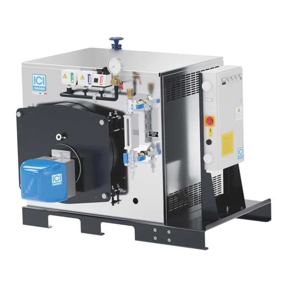
APPLIANCE DESCRIPTION FX N steam generating systems are medium-pressure type, 5 bar, with reverse flame in the furnace and fire tubes. The generator is supplied in monobloc design and can be matched to two-stage burners running on liquid and gaseous fuels. Thanks to the low water content, operating capacity is reached very quickly and ensures high efficiency, even with intermittent operation. -
Page 8: Dimensions And Connections
DIMENSIONS AND CONNECTIONS General information Cooke Industries - Phone: +64 9 579 2185 Email: sales@cookeindustries.co.nz Web: www.cookeindustries.co.nz... -
Page 9: Technical Data
Dimensions FX N Description u.m. 50 N 100 N 150 N 100 DUAL N 200 DUAL N 300 DUAL N 1130 1130 1130 1040 1040 1040 FX50 N FX100 N FX150 N 1360 1360 1360 1040 1040 1040 FX50 N FX100 N FX150 N 1060... -
Page 10: Control Panel
CONTROL PANEL The FX N steam generator is equipped with a control panel for managing and controlling the appliance. The type of panel is established according to the steam generator configuration. For more details refer to the layout and wiring diagram provided with the installed panel. -
Page 11: User Obligations
PAPERWORK These generators, supplied in single-block, are CE marked according to the Directive 2014/68/EU "PED". The documentation supplied with the generator is: – declaration of conformity of the whole – use and maintenance manual (always housed in the electrical panel) –... - Page 12 COMPONENTS The FX N steam generators are equipped with a set of components that can be divided into: – Safety components (safety valves, safety level switches, safety pressure switch). – Indicator components (level indicator, pressure gauge, flame warning light). – Adjustment components (level regulators, pressure switches, pressure transmitters). –...
- Page 13 OPERATING PRESSURE SWITCH The pressure switch allows adjusting generator pressure and keeping it close to the required value. For calibration, loosen the protection screws (fig. on the left) and remove the cover to reach the pressure switch. Trigger pressure and differential pressure can be set using the top screws (fig. on the right) and can be displayed on the two graduated scales.
-
Page 14: Safety Pressure Switch
SAFETY PRESSURE SWITCH The safety pressure switch is triggered in case of operating pressure switch fault and permanently stops the burner. The pressure switch is equipped with a single-pole switch, of which the position of the contact depends on the pressure on the relevant connection and on the value set. -
Page 15: Safety Valve
SAFETY VALVE It releases the steam when generator maximum design pressure is reached. The valve used on boilers is of the spring-type. The operator must pay the utmost attention to the safety valve, careful and accurate maintenance is important. The safety valve is the most important and delicate accessory of the generator, and ensures that the pressure in the generator never exceeds the design pressure. - Page 16 AUTOMATIC LEVEL REGULATOR It is of the electric conductivity type, with electronic relays in the electric panel. Operation involves water pump start and stop and a low level safety device: Probes in the cylinder: 6 Pump stop 7 Pump start-up 8 Burner shut off 1st safety device and alarm triggering 9 Burner shut off 2nd safety device and alarm triggering NOTE: It is recommended to add to the alarm buzzer in the boiler room...
- Page 17 SUPPLY Water is fed using a centrifugal pump. The pump should not be sucking against the inlet opening, but should rather be “under positive suction head”, i.e. under the pressure of a water column due to the difference in height between water level in the collection tank and the pump.
-
Page 18: Installation Room
Installation INSTALLATION ROOM Heating plant room The user is responsible for ensuring that the heating plant room is designed in compliance with the prevailing rules on the matter in the country of use. The user is responsible for ensuring that the heating plant room is designed in compliance with the prevailing rules on the matter in the country of use. -
Page 19: Electric Connections
OPERATION WITH ONE MODULE ONLY If only one of the two modules is permanently working, it is recommended to electrically and hydraulically shut off the module not working, by working the switches (disabling burner, pump and sludge drainage) on the panel and working the ball valves that shut off the pump and the corresponding steam outlet valve. - Page 20 COMMISSIONING FIRST START-UP (Electromechanical panel) Before start-up, open the door and insert the turbulators completely inside the front ends of the smoke pipes, taking care to push them inside by at least 100 mm. The figure is indicative • Check that all fittings are fully tightened. •...
-
Page 21: Maintenance
Maintenance ORDINARY • Bleed boiler and level indicators; • check the efficiency of the control and adjustment instruments by carefully examining the electrical parts, the connections and the mechanical parts (pressure switches); it is recommended to replace the probe ceramic spark plugs annually •... - Page 22 Cooke Industries - Phone: +64 9 579 2185 Email: sales@cookeindustries.co.nz Web: www.cookeindustries.co.nz...
-
Page 23: Dry Storage
EXTRAORDINARY Every generator must be periodically stopped to carry out a thorough inspection and maintenance: required interval is determined by your experience, by the operating conditions, by the quality of supply water and the type of fuel used. Before inspection or cleaning, thoroughly check that no water or steam can reach the generator through the connecting ducts. Each valve will have to be locked and, if necessary, isolated by removing a section of the connection pipe to the system or by placing a blind flange in-between. - Page 24 WATER CHARACTERISTICS The values in the following tables are extracted from tables 5.1 and 5.2 in EN 12953-10 (requirements concerning the quality of water supply and the water in the generator). Even for generators that are not covered by the aforementioned provision it is however necessary to adopt at least the indicated limits and however, to refer to the specialised companies that manage selecting the type of treatment to be carried out on the basis of a thorough analysis of the water available.
- Page 25 5.2 Operating water - threshold values Steam generator water with pressure up to 20 bar Boiler water for hot water CHARACTERISTICS u.m. boilers (total operating Direct conductivity of the Direct conductivity of the range) supply water > 30 μS/cm supply water ≤30 μS/cm Appearance Clear, limpid, without foam or suspended solids Direct conductivity at 25°C...
-
Page 26: Any Anomalies And Remedies
ANY ANOMALIES AND REMEDIES ANOMALY CAUSE REMEDY Exceeding of the max pressure regulated on the Adjustment of block pressure switches and/or limit valve that must be equal to the appliance design too high Safety valve(s) opening pressure Safety valve calibration loss The valve manufacturer will perform the overhaul Cleaning of seat by sometimes acting on the Dirt around the shutter seat... - Page 27 Residual Risk Management EXCESSIVE STEAM PRESSURE – Make sure the safety valves properly open at the design pressure. – It is necessary to check the correct activation of the shut-off pressure switch that eliminates the cause of pressure increase by stopping the burner.
- Page 28 CORROSION DUE TO OXYGEN – Carry out water analysis at the necessary time intervals (refer to user's manual). – Perform water treatments in order to bring the characteristic values back within the limits specified in the use and maintenance manual. (ref. EN12953-10) –...
- Page 29 MINIMUM TEMPERATURE – Make sure that the temperature the boiler can be subjected to complies to the design minimum permitted temperature. EARTHQUAKE – The appliance has not been dimensioned for installation in an earthquake zone ATMOSPHERIC CONDITIONS – Protect the generator against adverse climatic conditions. INSTALLATION AND START-UP –...
- Page 30 Once registered, authenticate your e-mail address by clicking on the link that will be sent by e-mail to the provided inbox. An additional e-mail will then be received with the credentials to access all services specifically developed by ICI CALDAIE S.p.A.
- Page 31 Notes Notes Cooke Industries - Phone: +64 9 579 2185 Email: sales@cookeindustries.co.nz Web: www.cookeindustries.co.nz...
- Page 32 ICI CALDAIE SpA 37059 Fraz. Campagnola di Zevio ( Verona) Italy Via G. Pascoli 38 Phone: +39 0458738511 Fax:+39 0458731148 info@icicaldaie.com www.icicaldaie.com Cooke Industries - Phone: +64 9 579 2185 Email: sales@cookeindustries.co.nz Web: www.cookeindustries.co.nz...
Need help?
Do you have a question about the FX N Series and is the answer not in the manual?
Questions and answers