
Related Manuals for ICI Caldaie MONOLITE JB Series


Summary of Contents for ICI Caldaie MONOLITE JB Series
- Page 1 TECHNICAL MANUAL MONOLITE GT CONDENSING BOILER WITH PREMIX BURNER MONOLITE JB CONDENSING BOILER (WITHOUT BURNER) LOW NOx STEEL CONDENSING BOILERS...
-
Page 3: Table Of Contents
TABLE OF CONTENTS GENERAL ..............................2 GENERAL WARNINGS..........................3 TECHNICAL SPECIFICATIONS ....................... 4 MONOLITE 45 GT – 350 GT..........................4 MONOLITE 30 JB - 670 JB ..........................6 INSTALLATION ............................9 HEATING SYSTEM............................. 9 4.1.1 Boiler room ..............................9 FLUE ................................... 9 4.2.1 Condensate drain ............................ -
Page 4: General
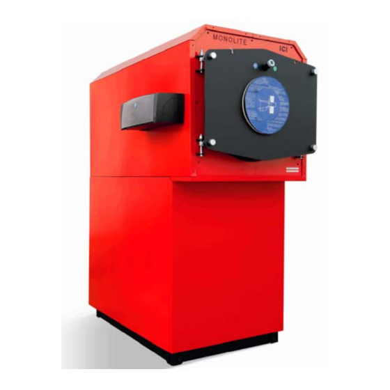
MONOLITE GENERAL The boilers of the MONOLITE series have a horizontal through-flame combustion chamber and a vertical condensing section of a special design, in stainless steel type AISI 316 Ti. These elements are immersed in water contained in a horizontal boiler drum with a vertical column to which the system inlet and outlet con- nections are fitted. -
Page 5: General Warnings
MONOLITE GENERAL WARNINGS Each generator is provided with a data plate that can be found in the envelope with the boiler documents. The plate lists: Serial number or identification code; Rated thermal output in kcal/h and in kW; ... -
Page 6: Technical Specifications
MONOLITE TECHNICAL SPECIFICATIONS MONOLITE 45 GT – 350 GT Efficiency 100% Effic. 100% NG max flow NG max flow NG max flow Max flow rate Characteristics Heat output Heat input (N.C.V.) (stars) rate G20 rate G30 rate G31 of flues kcal/h kcal/h kcal/h... - Page 7 MONOLITE Mod. 160 GT – 350 GT Dimensions MONOLITE 45 GT 1825 1734 1348 MONOLITE 70 GT 1825 1734 1348 MONOLITE 95 GT 1825 1734 1348 MONOLITE 125 GT 1825 1734 1348 MONOLITE 160 GT 2151 1941 1510 1952 2071 1063 MONOLITE 210 GT 2151...
-
Page 8: Monolite 30 Jb - 670 Jb
MONOLITE MONOLITE 30 JB - 670 JB Efficiency 100% Effic. 100% NG max flow NG max flow NG max flow Max flow rate Characteristics Heat output Heat input (N.C.V.) (stars) rate G20 rate G30 rate G31 of flues kcal/h kcal/h kcal/h m³/h kg/h... - Page 9 MONOLITE Mod. 30 JB - 125 JB Mod. 160 JB - 270 JB Boiler flow Boiler condensation drain Medium temperature return Inspection well Fitting for Instruments Low temperature return System filling/drainage Inspection plugs Safety valve(s) fitting Bulbs wells...
- Page 10 MONOLITE Mod. 350 JB - 670 JB Dimensions MONOLITE 30 JB 1825 1734 1348 MONOLITE 45 JB 1825 1734 1348 MONOLITE 75 JB 1825 1734 1348 MONOLITE 95 JB 1825 1734 1348 MONOLITE 125 JB 1825 1734 1348 MONOLITE 160 JB 2151 1941 1510...
-
Page 11: Installation
MONOLITE INSTALLATION Before connecting the boiler, carry out the following operations: Clean carefully all the system pipework to remove any residues that could damage impede correct boiler operation; Check that the flue has sufficient draught, has no restrictions, is free of all soot and residues, and is per- fectly gas tight in particular to the water vapour contained in the flue gas. -
Page 12: 4.3.1 Sealed Hot Water Heating System With Expansion Vessel
MONOLITE 4.3.1 SEALED HOT WATER HEATING SYSTEM WITH EXPANSION VESSEL Mod. 45 - 125 Mod. 160 - 270... - Page 13 MONOLITE Mod. 350 - 670 1 Hydraulic disconnect switch 22 Safety valve n° 1 (the 2 has a heating capacity 2 Filter a y above 580 kW) 3 Water flow switch 23 Fuel shut-off valve 4 Filling unit 24 Manual shut-off valve 5 Tundish with articulated joint 25 Manual shut-off valve for gas 6 Pressure gauge...
-
Page 14: Electrical Connection
MONOLITE ELECTRICAL CONNECTION The electrical system in a heating plant that is for building heating only, is the object of numerous regula- tions, some of which are general in character, others being specific to the type of application or type of fuel. -
Page 15: Inverting The Door Aperture (Mod. 45 Gt/125 Gt)
MONOLITE INVERTING THE DOOR APERTURE (MOD. 45 GT/125 GT) The door can be opened in either direction (RH or LH). For the door height adjustment see Fig. 2. Fig. 2 – Door clamping arm INVERTING THE DOOR APERTURE (mod. 160 GT/JB - 350 GT/670 JB) If the door is to be opened to the opposite side, act as follows: 1. -
Page 16: Pressurised Boiler Connection
MONOLITE PRESSURISED BOILER CONNECTION Before installation, clean the inside of all the fuel supply pipes, to remove any residues that might compro- mise correct boiler operation. Check the maximum combustion chamber pressure, as shown in the technical characteristics table. The observed value can increase by 20 % if the fuel used is not gas or light fuel oil, but heavy oil;... -
Page 17: Fitting The Boiler Casing
MONOLITE FITTING THE BOILER CASING BOILER BODY INSULATION (Fig. 4-5-6) Wrap glass wool (A) around the column and attach with the clips. Wrap glass wool (B) around the upper cylindrical boiler body without covering the shaft/bulb holder located near the flanged outlet pipe and fix in position with the clips supplied. -
Page 18: Boiler Casing Mod. 160 Gt/Jb-270 Gt/Jb (Fig. 5)
MONOLITE BOILER CASING mod. 160 GT/JB-270 GT/JB (Fig. 5) Fit the panel (1D) by hooking the upper profile to the square tube and the lower to the boiler longheron. Repeat the same procedure for panel (1S). Fit the panel (2D) by hooking the upper profile to the square section tube and inserting it in the slots in the lower panel. -
Page 19: Boiler Covering Mod. 350 Gt/Jb-670 Jb (Fig. 6)
MONOLITE BOILER COVERING mod. 350 GT/JB-670 JB (Fig. 6) Mount the panels (1D) fixing the lower folds on to the metal strut on the boiler and attaching the upper ones to the centre with the appropriate screws. Repeat the same procedure for the panels (1S). ... -
Page 20: Starting
MONOLITE STARTING IMPORTANT: before starting insert the flue gas baffles completely in the flue gas pipes, pushing them in by at least 100 mm. PRELIMINARY CHECKS Before starting the boiler, make sure that: The number plate data corresponds to the electrical, water and liquid or gas fuel supply data; The burner rating is compatible with that of the boiler;... -
Page 21: Operation
MONOLITE OPERATION OPERATION CHECKS The heating system must be used suitably, ensuring on the one hand, optimum combustion with reduced emission to the atmosphere of carbon monoxide, hydrocarbons and soot, and on the other avoiding all dam- age to persons and property. The pressurisation must remain within the limit values shown in the technical data table. - Page 22 Iscritto R.I. VR 02245640236 DECLARATION OF CONFORMITY WITH THE EUROPEAN COMMUNITY REGULATIONS I undersigned Emanuela Lucchini, Managing Director of ICI CALDAIE S.p.A. headquarted in via G. Pascoli 38 – 37059 Campagnola di Zevio (VR) Italia. DECLARE THAT BOILERS MONOLITE 45 GT, 70 GT, 95 GT, 125 GT with burner...
- Page 24 Appartenente al Gruppo Finluc, iscritto R.I. VR n. 02245640236 Via G. Pascoli, 38 - Zevio - fraz. Campagnola - VERONA - ITALIA Tel. 045/8738511 - Fax 045/8731148 info@icicaldaie.com - www.icicaldaie.com The data reported are indicative only and are not binding. Our company reserves the right to introduce alterations at any time as it deems fit and proper for the development of the product.
Need help?
Do you have a question about the MONOLITE JB Series and is the answer not in the manual?
Questions and answers